

Page 1
Find us at www.keysight.com Page 1
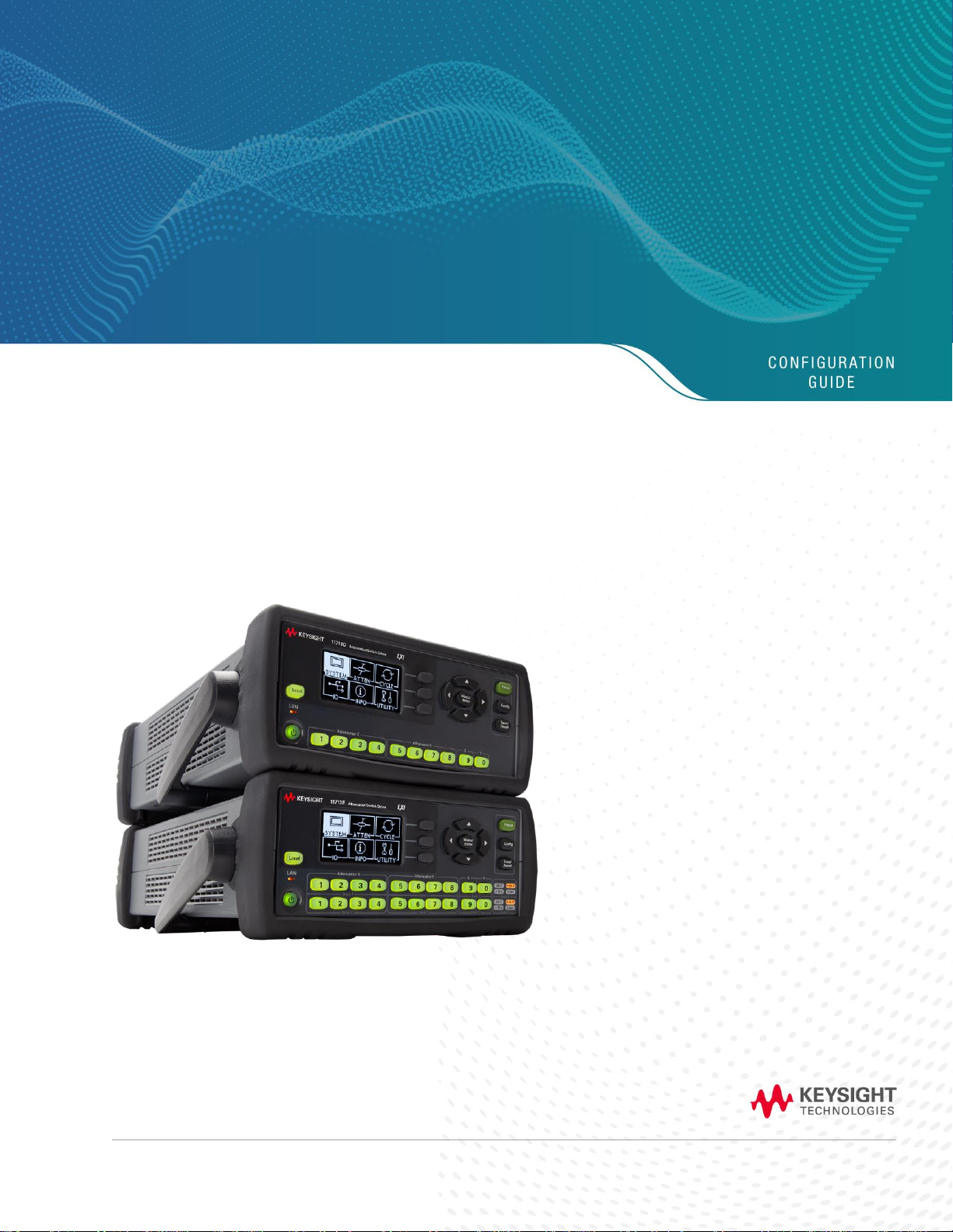
11713D/E Attenuator/Switch Drivers
This configuration guide will assist you through the
process of configuring a switching system using the
Keysight 11713D/E attenuator/switch drivers.
Page 2

Find us at www.keysight.com Page 2
Key Features
The Keysight 11713D/E attenuator/switch drivers provide remote or front panel drive control for
programmable attenuators and electromechanical or solid-state switches. Designed with both benchtop
and ATE environments in mind, these attenuator/ switch drivers provide an intuitive user interface, a
variety of switching options, software programmability and remote-control features for quick, easy
design validation and automated testing. Front panel pushbuttons and an easy-to-read LCD display
simplify setup of functions such as voltage, TTL functions, continuous or pulse-drive, IP address, etc.
The 11713D/E is an LXI Class C compliant instrument, so it can be easily controlled and triggered
remotely using a full-featured graphical web interface. This feature is used in high-volume production
environments. Software instrument drivers such as IVI-COM provide programming compatibility with
popular application development environments and support PC industry standards such as Component
Object Model (COM). Standard GPIB connectivity supports automated programmed scripting and
ensures backward compatibility to Keysight 11713B/C attenuator/switch drivers. These portable
instruments come in a half-rack, 2U design with self-contained current limiting power supplies. The
11713E model also includes integrated tri-voltage supplies of 5, 15 and 24 V and a user-defined
external input voltage capability to ensure 100% biasing compatibility to most relays in the market. The
11713E has two individual banks of outputs each with an independent voltage drive.
•
User-friendly interface provides quick set up, switching, and remote control of small-scale automated
test equipment (ATE)
•
Capability to drive Keysight’s programmable attenuators, electro-mechanical or solid-state switches with
continuous drive or pulse-drive selection
•
Controls up to 20 SPDT switches¹ concurrently, or a combination of 4 programmable attenuators and 4
SPDT switches
•
Multiple connectivity with LXI Class C compliance: GPIB, USB or LAN for easy remote integration
•
An integrated, tri-voltage power supply saves rack space (11713E only)
•
External VDC port connects any type of switch and provides forward compatibility for switches
•
Backward compatibility with the Keysight Technologies 11713B/C
•
Built-in counter monitors the life cycle of attenuators and switches
1. The number of switches and attenuators that can be driven will depend on the type of switch configurations and the attenua to r
sections. The 11713E capable of driving twice as many devices as the 11713D; however, the total load current that can be
consumed is still 3.4A.
2. Accepts most attenuators and switches available today. Including supporting solid state switches. Do not support 85331/2B solid
state switches and 8761A/B switches.
Model
11713D
11713E
Drives up to
Two programmable attenuators and two
electromechanical/solid state switches
Four programmable attenuators and four
electro-mechanical/solid state switches
Drives up to
10 SPDT switches 1
20 SPDT switches 1
Voltage
24 V
5, 15, 24 V and user selectable support
voltages
Voltage drive
1 bank of output
2 independent banks of outputs
Attenuators types
Any attenuator or switch 2
Any attenuator or switch 2
Switch types
Any attenuator or switch 2
Any attenuator or switch 2
Connectivity
GPIB, USB, LAN (LXI Class C)
GPIB, USB, LAN (LXI Class C)
Backwards
compatibility
Yes (with 11713B)
Yes (with 11713C)
Page 3
Find us at www.keysight.com Page 3
11713D/E System Specification
Specifications describe warranted performance over the temperature range 0 to +50 °C after one hour of
continuous operation, unless otherwise noted.
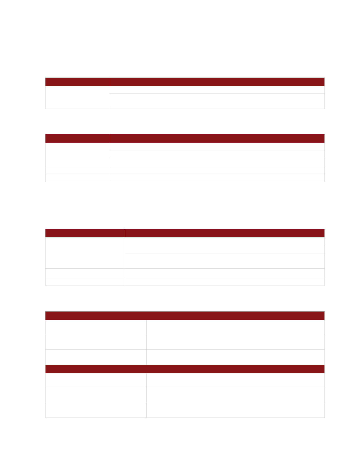
Drive power Supply
11713D
Current
3.4 A maximum continuous current
Contact pairs 1 through 8, 9, and 0, total maximum current of 3.4 A continuous
through all contacts (< 0.7 A per contact)
11713D/E Remote Programming
Drive power supply
11713D/E
Interface
GPIB interface operates to IEEE 488.2 and IEC65
10/100 BaseT LAN interface
USB 2.0 interface
Command language
SCPI standard interface commands (Keysight 11713B/C backward compatible)
GPIB compatibility
SH0, AH1, T0, TE0, L2, LE0, SR0, RL1, PP0, DC0, DT0, C0
11713D/E Supplemental Specifications and Characteristics
Supplemental characteristics are intended to provide useful information. They are typical but nonwarranted performance parameters.
Drive power supply
11713D/E
Power
100 to 240 Vac, automatic selection, 50/60 Hz
160 VA maximum
Mains supply voltage fluctuations are not to exceed 10% of the nominal
supply voltage
Maximum load inductance
500 mH
Maximum load capacitance
< 0.01 µF for contact pairs 9 and 0
Mechanical Information
11713D product dimensions
Net weight
With rubber bumper and handle: 3.5 kg (7.7 lbs)
Without rubber bumper and handle: 3.1 kg (6.8 lbs)
Dimension (H x W x D) with handle
and rubber bumper
103.0 mm x 261.3 mm x 378.7 mm
(4.06 inches x 10.29 inches x 14.91 inches)
Dimension (H x W x D) without
handle and rubber bumper
87.7 mm x 212.7 mm x 364.1 mm
(3.45 inches x 8.37 inches x 14.34 inches)
11713E product dimensions
Net weight
With rubber bumper and handle: 3.6 kg (7.9 lbs)
Without rubber bumper and handle: 3.2 kg (7.1 lbs)
Dimension (H x W x D) with handle
and rubber bumper
103.0 mm x 261.3 mm x 378.7 mm
(4.06 inches x 10.29 inches x 14.91 inches)
Dimension (H x W x D) without
handle and rubber bumper
87.7 mm x 212.7 mm x 364.1 mm
(3.45 inches x 8.37 inches x 14.34 inches)
Page 4
Find us at www.keysight.com Page 4
Product Configuration
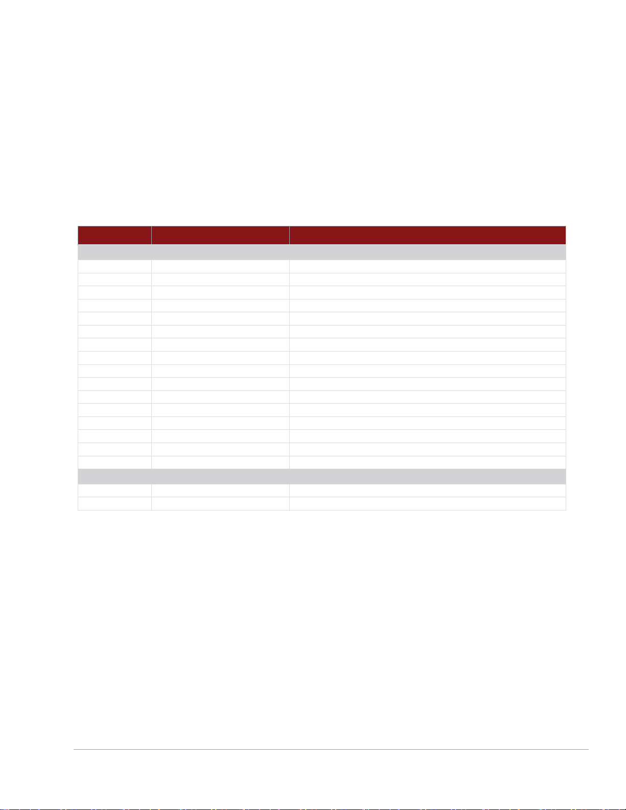
The 11713D/E attenuator/switch drivers can be configured easily. The connection between the driver
and switching devices is intuitive and direct. Simply select the appropriate interface cable and you can
make point-to- point connection from the driver to the attenuator(s) and/or switch(es). Details such as
pin numbers and wires color are provided in the tables found in Configuration Information for Switches
and Configuration Information for Attenuators sections.
Note 1: The maximum quantity orderable for each cable option is 9.
Note 2: The length of cables below is 60 inches (5 ft).
11713D/E
Part number
Description
Cable Options
Option 001
11764-60004
Viking connector to 10-pin DIP connector
Option 101
8120-2703
Viking connector to viking connector
Option 102
11713-60068
Viking connector to 4 cables with 4-conductor bare wires
Option 103
11713-60069
Viking connector to 2 cables with 5-conductor bare wires
Option 104
11713-60071
Viking connector to 4 cables with 3-pin connector
Option 105
11713-60072
Viking connector to 4 cables with 3-conductor bare wires
Option 106
11713-60073
Dual Viking connector to 24-pin connector
Option 107
11713-60074
Triple Viking connector to 24-pin connector
Option 201
5061-0969
Viking connector to 12-pin conductor cable, bare wire
Option 301
11761-60001
Viking connector to (4) ribbon cables
Option 401
11713-60042
Dual-viking connector to 16-pin DIP connector
Option 501
11713-60043
Viking connector to (4) 9-pin Dsub connectors
Option 502
11713-60049
Viking connector to (2) 9-pin Dsub connectors
Option 601
11713-60044
Viking connector to 16-pin DIP connector
Option 701
5064-7848
Viking connector to 14-pin DIP connector
Option 801
11713-60047
Viking connector to (4) 10-pin DIP connectors
Rack mount kit options (optional)
Option 908
5063-9240
Rack mount kit for one instrument
Option 909
5061-9694 and 5063-9212
Rack mount kit for two instruments
Page 5
Find us at www.keysight.com Page 5
Five Simple Steps to Configure your Switching System
1. Determine the switching device’s model and option (DC connector).
•
Example
•
Model: 87104A (SP4T switch)
•
Option: 100 (solder terminal)
2. Determine the attenuator/switch driver’s model and option (interface cable).
•
Example
•
Model: 11713D
•
Option: 201 (Viking connector to 12-pin conductor cable, bare wire)
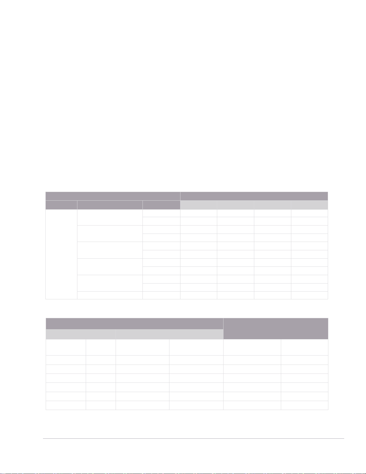
3. Use the selection guide, Table A (page 6) for switches and Table B (page 7) for attenuators.
•
Example
•
Selection guide: Table A (for switches)
•
Configuration table: Table F-1
11713D/E
Switches
Model
Option
001
101
201
601
SP4T
87104A/B/C/D/P/Q/R
100
Table F-1
161 Table F-2
87204A/B/C
100
Table G-1
161 Table G-2
L7104A/B/C
100
Table F-1
161 Table F-2
L7204A/B/C
100
Table F-1
161 Table F-2
8767K
016
Table J-1
060 Table J-2
8767M
No option
Table L
4. Configure your switching system using Table F-1 (page 13) as a reference.
From 11713D/E (Option 201)
To 87104A/B/C/D, 87104P/Q/R,
L7104A/B/C and L7204A/B/C SP4T
(Option 100)
Front panel pushbutton
Interface cable
Attenuator X
LED
Viking connector
pin number
Bare wire color
Solder terminal
number
RF path
– – 1 (VCC)
Red
1 – – – 2 (GND)
White/Brown
15
–
1
OFF
5
Violet
5
2 to C closed
2
OFF
7
Black
7
3 to C closed
3
OFF
9
Orange
11
5 to C closed
4
OFF
11
Brown
13
6 to C closed
5. Operate your system.
Page 6
Find us at www.keysight.com Page 6
Table A: Selection guide for switches
Electro-mechanical switches
11713D/E
Switches
Model
Option
201
501
502
Bypass
8763A/B/C
001/015/024
Table D-2
T15/T24
Table D-5
8764A/B/C
011/015/024
Table D-3
T15/T24
Table D-6
N1811T, N1811TL
202
Table O-11
201 Table O-12
202/401
Table O-15
201/401
Table O-16
N1812U, N1812UL
202
Table O-9
201 Table O-10
202/401
Table O-13
201/401
Table O-14
11713D/E
Switches
Model
Option
201
301
501
502
SPDT
8762A/B/C/F
011/015/024
Table D-1
T5/T24
Table D-4
8765A/B/C/D,
8765F 1
305/310/315/324
Table E-1
005/010/015/024
Table E-2
N1810U,
N1810UL
202
Table O-1
201
Table O-2
202/401
Table O-5
Table O-6
201/401
N1810T,
N1810TL
202
Table O-3
201
Table O-4
202/401
Table O-7
201/401
Table O-8
11713D/E
Switches
Model
Option
001
101
SP3T
8766K
016
Table J-1
060 Table J-2
1. 8765A/B/C/D/F require continuous current to latch. The number of switches for connection depends on option selection.
Page 7
Find us at www.keysight.com Page 7
11713D/E
Switches
Model
Option
001
101
201
601
SP4T
87104A/B/C/D/P/Q/R
100
Table F-1
161 Table F-2
87204A/B/C
100
Table G-1
161 Table G-2
L7104A/B/C
100
Table F-1
161 Table F-2
L7204A/B/C
100
Table F-1
161 Table F-2
8767K
016
Table J-1
060 Table J-2
8767M
No option
Table L
11713D/E
Switches
Model
Option
001
101
SP5T
8768K
016
Table J-1
060 Table J-2
8768M
No option
Table L
11713D/E
Switches
Model
Option
101
201
401
701
SP6T
87106A/B/C/D/P/Q/R
100 Table H-1
161
Table H-2
87206A/B/C
100 Table I-1
161
Table I-2
L7106A/B/C
100 Table H-1
161
Table H-2
L7206A/B/C
100 Table H-1
161
Table H-2
8769K
060
Table K
8769M
No option
Table M
Page 8

Find us at www.keysight.com Page 8
11713D/E
Switches
Model
Option
106
107
201
601
SP4T
U7104E/N/F
200 Table Q-1
300 Table Q-1
400
Table Q-2
500
Table Q-2
SP6T
U7106E/NF
200 Table Q-3
300 Table Q-3
400
Table Q-4
500
Table Q-4
SP8T
U7108A/B/C
200
Table P-1
300
Table P-1
400
Table P-2
500
Table P-2
SP10T
U7110A/B/C
200 Table P-3
300 Table P-3
400
Table P-4
500
Table P-4
11713D/E
Switches
Model
Option
201
401
Matrix
87406B/Q
100
Table H-1
161 Table H-2
87606B/Q
100
Table I-1
161 Table I-2
11713D/E
Switches
Model
Option
201
801
Transfer
87222C/D/E/R
100
Table N-1
161 Table N-2
L7222C
100
Table N-1
161 Table N-2
Page 9
Find us at www.keysight.com Page 9
Switch Option Descriptions
•
011: 5 Vdc
•
015: 15 Vdc
•
024: 24 Vdc
•
T15: TTL/5V CMOS compatible logic with 15 Vdc supply
•
T24: TTL/5V CMOS compatible logic with 24 Vdc supply
•
200: Standard 24 VDC and 24-PIN DIP DC connector with-24 inch ribbon cable, bare wire
•
300: TTL 24 VDC and 24-PIN DIP DC connector with 24-inch ribbon cable, bare wire
•
400: Standard 24 VDC and Solder Terminals
•
500: TTL 24 VDC and Solder Terminals
•
201: D‑submini 9 pin (f)
•
202: Solder lug
•
401: TTL/5V CMOS compatible
•
305: 5 Vdc with solder terminals
•
310: 10 Vdc with solder terminals
•
315: 15 Vdc with solder terminals
•
324: 24 Vdc with solder terminals
•
005: 5 Vdc with 3‑inch ribbon cable
•
010: 10 Vdc with 3‑inch ribbon cable
•
016: 16‑inch ribbon cables
•
060: Viking cable connector
•
100: Solder terminals
•
161: Ribbon receptacle
Solid state switches
11713D/E
Solid State
Switches
Models
Option
102
103
104
105
201
SPDT
U9397A/C
No option
Table W
P9402A/C
No option
Table U
SP4T
P9404A/C
No option
Table X
Transfer
P9400A/C
No option
Table T
U9400A/C
No option
Table V
Page 10

Find us at www.keysight.com Page 10
Table B: Selection guide for attenuators
XXXX
Attenuators Model
Option
001
101
8494G/H
016
Table R-1
060 Table R-2
8495G/H
016
Table R-1
060 Table R-2
8496G/H
016
Table R-1
060 Table R-2
8495K
016
Table R-1
060 Table R-2
8497K
016
Table R-1
060 Table R-2
84904K/L/M
No option
Table S
84905M
No option
Table S
84906K/L
No option
Table S
84907K/L
No option
Table S
84908M
No option
Table S
Attenuator Option Description
•
Option 060: 12-pin Viking connector
•
Option 016: 16-inch ribbon cable with 14-pin DIP plug
Configuration Information for Switches
Electro-mechanical switches
Note 1: Each table below illustrates the configuration of five switches to the 11713D/E.
Note 2: Five additional switches can be driven by Attenuator Y (front panel pushbuttons 5, 6, 7, 8 and 0)
using the same configuration as Attenuator X.
Page 11

Find us at www.keysight.com Page 11
Table D-1: Configuration of 11713D/E (Option 201) to 8762A/B/C/F SPDT switches
(Option 005/011/024)
From 11713D/E (Option 201)
To 8762A/B/C/F (Option 005/011/024)
Front panel pushbutton
Interface cable
Attenuator X
LED
Viking
connector pin
number
Bare wire
color
Solder
terminal
number
RF path
Device Under
Test (DUT)
– – 1 (VCC)
Red
C
–
VCC for all 5
DUTs
1
OFF
5
Violet
1
1 to C closed, 2
terminated
DUT 1
ON 6 Yellow
2
2 to C closed, 1
terminated
2
OFF
7
Black
1
1 to C closed, 2
terminated
DUT 2
ON 8 Green
2
2 to C closed, 1
terminated
3
OFF
9
Orange
1
1 to C closed, 2
terminated
DUT 3
ON
10
Blue
2
2 to C closed, 1
terminated
4
OFF
11
Brown
1
1 to C closed, 2
terminated
DUT 4
ON
12
White
2
2 to C closed, 1
terminated
9
OFF
4
Gray
1
1 to C closed, 2
terminated
DUT 5
ON 3 White/Red
2
2 to C closed, 1
terminated
Page 12

Find us at www.keysight.com Page 12
Table D-2: Configuration of 11713D/E (Option 201) to 8763A/B/C bypass switches
(Option 005/011/024)
From 11713D/E (Option 201)
To 8763A/B/C (Option 005/011/024)
Front panel pushbutton
Interface cable
Attenuator X
LED
Viking
connector pin
number
Bare wire
color
Solder
terminal
number
RF path
Device Under
Test (DUT)
– – 1 (VCC)
Red
C
–
VCC for all 5
DUTs
1
OFF
5
Violet
1
1 to 2 closed, 3 to
4 closed
DUT 1
ON 6 Yellow
2
1 terminated, 2 to
3 closed, 4 open
2
OFF
7
Black
1
1 to 2 closed, 3 to
4 closed
DUT 2
ON 8 Green
2
1 terminated, 2 to
3 closed, 4 open
3
OFF
9
Orange
1
1 to 2 closed, 3 to
4 closed
DUT 3
ON
10
Blue
2
1 terminated, 2 to
3 closed, 4 open
4
OFF
11
Brown
1
1 to 2 closed, 3 to
4 closed
DUT 4
ON
12
White
2
1 terminated, 2 to
3 closed, 4 open
9
OFF
4
Gray
1
1 to 2 closed, 3 to
4 closed
DUT 5
ON 3 White/Red
2
1 terminated, 2 to
3 closed, 4 open
Page 13

Find us at www.keysight.com Page 13
Table D-3 Configuration of 11713D/E (Option 201) to 8764A/B/C bypass switches
(Option 005/011/024)
From 11713D/E (Option 201)
To 8764A/B/C (Option 005/011/024)
Front panel pushbutton
Interface cable
Attenuator X
LED
Viking
connector pin
number
Bare wire
color
Solder terminal
number
RF path
Device Under
Test (DUT)
– – 1 (VCC)
Red
C
–
VCC for all 5
DUTs
1
OFF
5
Violet
1
1 open, 2 to 3
closed, 4 to 5
closed
DUT 1
ON 6 Yellow
2
1 to 2 closed, 3
to 4 closed, 5
open
2
OFF
7
Black
1
1 open, 2 to 3
closed, 4 to 5
closed
DUT 2
ON 8 Green
2
1 to 2 closed, 3
to 4 closed, 5
open
3
OFF
9
Orange
1
1 open, 2 to 3
closed, 4 to 5
closed
DUT 3
ON
10
Blue
2
1 to 2 closed, 3
to 4 closed, 5
open
4
OFF
11
Brown
1
1 open, 2 to 3
closed, 4 to 5
closed
DUT 4
ON
12
White
2
1 to 2 closed, 3
to 4 closed, 5
open
9
OFF
4
Gray
1
1 open, 2 to 3
closed, 4 to 5
closed
DUT 5
ON 3 White/Red
2
1 to 2 closed, 3
to 4 closed, 5
open
Note 1: Each table below illustrates the configuration of five switches to the 11713D/E.
Note 2: Five additional switches can be driven by Attenuator Y (front panel pushbuttons 5, 6, 7, 8 and 0) using the same configuration as
Attenuator X.
Page 14

Find us at www.keysight.com Page 14
Table D-4: Configuration of 11713D/E (Option 201) to 8762A/B/C SPDT switches (Option T15/T24)
From 11713D/E (Option 201)
To 8762A/B/C (Option T15/T24)
Front panel pushbutton
Interface cable
Attenuator X
LED
Viking
connector pin
number
Bare wire color
Solder
terminal
number
RF path
Device Under
Test (DUT)
– – 1 (VCC)
Red
C
–
VCC for all 5
DUTs
– – 2 (GND)
White/Brown
2
–
GND for all 5
DUTs
1
OFF
5
Violet
1
1 to C closed, 2
terminated
DUT 1
ON
2 to C closed, 1
terminated
2
OFF
7
Black
1
1 to C closed, 2
terminated
DUT 2
ON
2 to C closed, 1
terminated
3
OFF
9
Orange
1
1 to C closed, 2
terminated
DUT 3
ON
2 to C closed, 1
terminated
4
OFF
11
Brown
1
1 to C closed, 2
terminated
DUT 4
ON
2 to C closed, 1
terminated
9
OFF
4
Gray
1
1 to C closed, 2
terminated
DUT 5
ON
2 to C closed, 1
terminated
Page 15

Find us at www.keysight.com Page 15
Table D-5: Configuration of 11713D/E (Option 201) to 8763A/B/C bypass switches
(Option T15/T24)
From 11713D/E (Option 201)
To 8763A/B/C (Option T15/T24)
Front panel pushbutton
Interface cable
Attenuator X
LED
Viking
connector pin
number
Bare wire color
Solder
terminal
number
RF path
Device Under
Test (DUT)
– – 1 (VCC)
Red
C
–
VCC for all 5
DUTs
– – 2 (GND)
White/Brown
2
–
GND for all
5 DUTs
1
OFF
5
Violet
1
1 to 2 closed, 3 to 4
closed
DUT 1
ON
1 terminated, 2 to 3
closed, 4 open
2
OFF
7
Black
1
1 to 2 closed, 3 to 4
closed
DUT 2
ON
1 terminated, 2 to 3
closed, 4 open
3
OFF
9
Orange
1
1 to 2 closed, 3 to 4
closed
DUT 3
ON
1 terminated, 2 to 3
closed, 4 open
4
OFF
11
Brown
1
1 to 2 closed, 3 to 4
closed
DUT 4
ON
1 terminated, 2 to 3
closed, 4 open
9
OFF
4
Gray
1
1 to 2 closed, 3 to 4
closed
DUT 5
ON
1 terminated, 2 to 3
closed, 4 open
Page 16

Find us at www.keysight.com Page 16
Table D-6: Configuration of 11713D/E (Option 201) to 8764A/B/C bypass switches
(Option T15/T24)
From 11713D/E (Option 201)
To 8764A/B/C (Option T15/T24)
Front panel pushbutton
Interface cable
Attenuator X
LED
Viking
connector pin
number
Bare wire
color
Solder
terminal
number
RF path
Device
Under Test
(DUT)
– – 1 (VCC)
Red
C
–
VCC for all
5 DUTs
– – 2 (GND)
White/Brown
2
–
GND for all
5 DUTs
1
OFF
5
Violet
1
1 open, 2 to 3 closed, 4
to 5 closed
DUT 1
ON
1 to 2 closed, 3 to 4
closed, 5 open
2
OFF
7
Black
1
1 open, 2 to 3 closed, 4
to 5 closed
DUT 2
ON
1 to 2 closed, 3 to 4
closed, 5 open
3
OFF
9
Orange
1
1 open, 2 to 3 closed, 4
to 5 closed
DUT 3
ON
1 to 2 closed, 3 to 4
closed, 5 open
4
OFF
11
Brown
1
1 open, 2 to 3 closed, 4
to 5 closed
DUT 4
ON
1 to 2 closed, 3 to 4
closed, 5 open
9
OFF
4
Gray
1
1 open, 2 to 3 closed, 4
to 5 closed
DUT 5
ON
1 to 2 closed, 3 to 4
closed, 5 open
Note 1: Each table below illustrates the configuration of five switches to the 11713D/E.
Note 2: The number of switches available for connection depends on option selection.
Note 3: Five switches can be driven by Attenuator Y (front panel pushbuttons 5, 6, 7, 8 and 0) using the same configuration as Attenuator X.
Page 17
Find us at www.keysight.com Page 17
Table E-1: Configuration of 11713D/E (Option 201) to 8765A/B/C/D/F SPDT switches (Options 3xx)
From 11713D/E (Option 201)
To 8765A/B/C/D/F (Option 305/310/315/324)
Front panel pushbutton
Interface cable
Attenuator X
LED
Viking
connector pin
number
Bare wire
color
Solder
terminal
number
RF path
Device Under
Test (DUT)
‑ ‑ 1 (VCC)
Red
2 and 3
‑
VCC for all 5
DUTs
1
OFF
5
Violet
1
2 to C closed, 1 open
DUT 1
ON 6 Yellow
4
1 to C closed, 2 open
2
OFF
7
Black
1
2 to C closed, 1 open
DUT 2
ON 8 Green
4
1 to C closed, 2 open
3
OFF
9
Orange
1
2 to C closed, 1 open
DUT 3
ON
10
Blue
4
1 to C closed, 2 open
4
OFF
11
Brown
1
2 to C closed, 1 open
DUT 4
ON
12
White
4
1 to C closed, 2 open
9
OFF
4
Gray
1
2 to C closed, 1 open
DUT 5
ON 3 White/Red
4
1 to C closed, 2 open
Table E-2: Configuration of 11713D/E (Option 301) to 8765A/B/C/D/F SPDT switches (Options 0xx)
From 11713D/E (Option 301)
To 8765A/B/C/D/F (Option 005/010/015/024)
Front panel pushbutton
Interface cable
Attenuator X
LED
Viking connector pin
number/banana jack
(rear panel)
5‑pin
receptacle
pin number
Ribbon
cable
connector
pin number
RF path
Device
Under Test
(DUT)
–
–
1 (VCC)/VDC
COM
3 and 4
3 and 4
–
VCC for
all 5 DUTs
1
OFF
5 1 1
2 to C closed, 1 open
DUT 1
ON 6 5 5 1 to C closed, 2 open
2
OFF
7 1 1
2 to C closed, 1 open
DUT 2
ON 8 5 5 1 to C closed, 2 open
3
OFF
9 1 1
2 to C closed, 1 open
DUT 3
ON
10 5 5
1 to C closed, 2 open
4
OFF
11 1 1
2 to C closed, 1 open
DUT 4
ON
12 5 5
1 to C closed, 2 open
9
OFF
S9‑A
— 1 2 to C closed, 1 open
DUT 5
ON
S9‑B
— 5 1 to C closed, 2 open
Note 1: Each table below illustrates the configuration of one switch to the 11713D/E.
Note 2: For switches with Option 161, ground pin 16 open all paths. Use S9 for Attenuator X or S0 for Attenuator Y. Do not close any path and
ground pin 16 simultaneously as this makes the switch buzz. *
Note 3: For switches with Option 100, there are no solder terminals available to open all paths.
Note 4: Solder terminal/DIP connector with pin numbers 6, 8, 12 and 14 provides indicator function.
Note 5: Applies to both Option 024 (standard/non-TTL drive) and Option T24 (TTL drive).
Note 6: One additional switch can be driven by Attenuator Y (front panel pushbuttons 5, 6, 7 and 8) using the same configuration as Attenuator X.
Page 18
Find us at www.keysight.com Page 18
Table F-1: Configuration of 11713D/E (Option 201) to 87104A/B/C/D, 87104P/Q/R, L7104A/B/C
and L7204A/B/C SP4T switches (Option 100)
From 11713D/E (Option 201)
To 87104A/B/C/D, 87104P/Q/R, L7104A/B/C
and L7204A/B/C SP4T (Option 100)
Front panel pushbutton
Interface cable
Attenuator X
LED
Viking connector
pin number
Bare wire color
Solder terminal
number
RF path
– – 1 (VCC)
Red
1
–
– – 2 (GND)
White/Brown
15
–
1
OFF
5
Violet
5
2 to C closed
2
OFF
7
Black
7
3 to C closed
3
OFF
9
Orange
11
5 to C closed
4
OFF
11
Brown
13
6 to C closed
Table F-2: Configuration of 11713D/E (Option 601) to 87104A/B/C/D, 87104P/Q/R, L7104A/B/C
and L7204A/B/C SP4T switches (Option 161)
From 11713D/E (Option 601)
To 87104A/B/C/D, 87104P/Q/R, L7104A/B/C
and L7204A/B/C SP4T (Option 161)
Front panel pushbutton
Interface cable
Attenuator X
LED
Viking connector
pin number
16‑pin DIP pin
number
RF path
– – 1 (VCC)
1 – – – 2 (GND)
15 – 1
OFF
5 5 2 to C closed
2
OFF
7 7 3 to C closed
3
OFF
9
11
5 to C closed
4
OFF
11
13
6 to C closed
Note 1: Each table below illustrates the configuration of one switch to the 11713D/E.
Note 2: For switches with Option 161, ground pin 16 opens all paths. Use S9 for Attenuator X or S0 for Attenuator Y. Do not close any path
and ground pin 16 simultaneously as this makes the switch to buzz. *
Note 3: For switch with Option 100, no solder terminal available to open all paths.
Note 4: Applies to both Option 024 (standard/non-TTL drive) and Option T24 (TTL drive).
Note 5: One additional switch can be driven by Attenuator Y (front panel pushbuttons 5, 6, 7 and 8) using the same configuration as
Attenuator X.
Page 19
Find us at www.keysight.com Page 19
Table G-1: Configuration of 11713D/E (Option 201) to 87204A/B/C SP4T switches (Option 100)
From 11713D/E (Option 201)
To 87204A/B/C (Option 100)
Front panel pushbutton
Interface cable
Attenuator X
LED
Viking connector
pin number
Bare wire color
Solder terminal
number
RF path
– – 1 (VCC)
Red
1
–
– – 2 (GND)
White/Brown
15
–
1
OFF
5
Violet
5
2 to C closed
ON 6 Yellow
6
2 to C opened
2
OFF
7
Black
7
3 to C closed
ON 8 Green
8
3 to C opened
3
OFF
9
Orange
11
5 to C closed
ON
10
Blue
12
5 to C opened
4
OFF
11
Brown
13
6 to C closed
ON
12
White
14
6 to C opened
Table G-2: Configuration of 11713D/E (Option 601) to 87204A/B/C SP4T switches (Option 161)
From 11713D/E (Option 601)
To 87204A/B/C (Option 161)
Front panel pushbutton
Interface cable
Attenuator X
LED
Viking connector
pin number
16‑pin DIP pin
number
RF path
– – 1 (VCC)
1 – – – 2 (GND)
15
– 1 OFF
5 5 2 to C closed
ON 6 6
2 to C opened
2
OFF
7 7 3 to C closed
ON 8 8
3 to C opened
3
OFF
9
11
5 to C closed
ON
10
12
5 to C opened
4
OFF
11
13
6 to C closed
ON
12
14
6 to C opened
Note 1: Each table below illustrates the configuration of one switch to the 11713D/E.
Note 2: For switches with Option 161, ground pin 16 opens all paths. Use S9 for Attenuator X or S0 for Attenuator Y. Do not close any path
and ground pin 16 simultaneously as this makes the switch to buzz. *
Note 3: For switch with Option 100, no solder terminal available to open all paths.
Note 4: Solder terminal/DIP connector with pin numbers 4, 6, 8, 10, 12 and 14 provides indicator function.
Note 5: Applies to both Option 024 (standard/non-TTL drive) and Option T24 (TTL drive).
Page 20
Find us at www.keysight.com Page 20
Table H-1: Configuration of 11713D/E (Option 201) to 87106A/B/C/D, 87106P/Q/R, L7106A/B/C
and L7206A/B/C SP6T switches (Option 100) and 87406B/Q matrix switch (Option 100)
From 11713D/E (Option 201 - quantity 2)
To 87106A/B/C/D, 87106P/Q/R,
L7106A/B/C and L7206A/B/C SP6T and
87406B/Q (Option 100)
Front panel pushbutton
Interface cable
Attenuator X/Y
LED
Viking connector
pin number
Bare wire color
Solder terminal
number
RF path
– – 1 (VCC)
Red
1
–
– – 2 (GND)
White/Brown
15 – 1
OFF
Cable 1‑5
Violet
3
1 to C closed
2
OFF
Cable 1‑7
Black
5
2 to C closed
3
OFF
Cable 1‑9
Orange
7
3 to C closed
4
OFF
Cable 1‑11
Brown
9
4 to C closed
5
OFF
Cable 2‑5
Violet
11
5 to C closed
6
OFF
Cable 2‑7
Black
13
6 to C closed
Table H-2: Configuration of 11713D/E (Option 401) to 87106A/B/C/D, 87106P/Q/R, L7106A/B/C
and L7206A/B/C SP6T switches (Option 161) and 87406B/Q matrix switch (Option 161)
From 11713D/E (Option 401)
To 87106A/B/C/D, 87106P/Q/R,
L7106A/B/C and L7206A/B/C SP6T and
87406B/Q (Option 161)
Front panel pushbutton
Interface cable
Attenuator X/Y
LED
Viking connector
pin number
16‑pin DIP pin
number
RF path
– – 1 (VCC)
1
–
– – 2 (GND)
15
–
1
OFF
P1‑5
3
1 to C closed
2
OFF
P1‑7
5
2 to C closed
3
OFF
P1‑9
7
3 to C closed
4
OFF
P1‑11
9
4 to C closed
5
OFF
P2‑5
11
5 to C closed
6
OFF
P2‑7
13
6 to C closed
Note 1: Each table below illustrates the configuration of one switch to the 11713D/E.
Note 2: For switches with Option 161, ground pin 16 opens all paths. Use S9 for Attenuator X or S0 for Attenuator Y. Do not close any path
and ground pin 16 simultaneously as this makes the switch to buzz. *
Note 3: For switch with Option 100, no solder terminal available to open all paths.
Note 4: Applies to both Option 024 (standard/non-TTL drive) and Option T24 (TTL drive).
Page 21
Find us at www.keysight.com Page 21
Table I-1: Configuration of 11713D/E (Option 201) to 87206A/B/C SP6T switches (Option 100)
and 87606B/Q matrix switch (Option 100)
From 11713D/E (Option 201 - quantity 2)
To 87206A/B/C and 87606B/Q
(Option 100)
Front panel pushbutton
Interface cable
Attenuator
X/Y
LED
Viking connector
pin number
Bare wire color
Solder terminal
number
RF path
– – 1 (VCC)
Red
1
–
– – 2 (GND)
White/Brown
15
–
1
OFF
Cable 1‑5
Violet
3
1 to C closed
ON
Cable 1‑6
Yellow
4
1 to C opened
2
OFF
Cable 1‑7
Black
5
2 to C closed
ON
Cable 1‑8
Green
6
2 to C opened
3
OFF
Cable 1‑9
Orange
7
3 to C closed
ON
Cable 1‑10
Blue
8
3 to C opened
4
OFF
Cable 1‑11
Brown
9
4 to C closed
ON
Cable 1‑12
White
10
5 to C opened
5
OFF
Cable 2‑5
Violet
11
5 to C closed
ON
Cable 2‑6
Yellow
12
5 to C opened
6
OFF
Cable 2‑7
Black
13
6 to C closed
ON
Cable 2‑8
Green
14
6 to C opened
Table I‑2: Configuration of 11713D/E (Option 401) to 87206A/B/C SP6T switches (Option 161)
and 87606B/Q matrix switch (Option 161)
From 11713D/E (Option 401)
To 87206A/B/C and 87606B/Q
(Option 161)
Front panel pushbutton
Interface cable
Attenuator
X/Y
LED
Viking connector
pin number
16‑pin DIP pin
number
RF path
– – 1 (VCC)
1 – – – 2 (GND)
15
–
1
OFF
P1‑5
3
1 to C closed
ON
P1‑6
4
1 to C opened
2
OFF
P1‑7
5
2 to C closed
ON
P1‑8
6
2 to C opened
3
OFF
P1‑9
7
3 to C closed
ON
P1‑10
8
3 to C opened
4
OFF
P1‑11
9
4 to C closed
ON
P1‑12
10
4 to C opened
5
OFF
P2‑5
11
5 to C closed
ON
P2‑6
12
5 to C opened
6
OFF
P2‑7
13
6 to C closed
ON
P2‑8
14
6 to C opened
Note 1: Each table below illustrates the configuration of one switch to the 11713D/E.
Note 2: With assumption that the initial state of switch’s RF path is thru.
Note 3: One additional switch can be driven by Attenuator Y (front panel pushbuttons 5, 6, 7 and 8) using the same configuration as
Attenuator X.
Page 22

Find us at www.keysight.com Page 22
Table J-1: Configuration of 11713D/E (Option 001) to 8766K, 8767K and 8768K switches
(Option 016)
From 11713D/E (Option 001)
To 8766K, 8767K and 8768K (Option 016)
Front panel pushbutton
Interface cable
8766K
8767K
8768K
Attenuator X
LED
Viking
connector
pin number
10‑pin DIP
pin number
RF path
– – 1 (VCC)
10 – –
– 1 OFF
5 1 Bypass 1
Bypass 3
Bypass 4
ON 6 2
1 to C closed
3 to C closed
4 to C closed
2
OFF
7 5 Bypass 2
Bypass 1
Bypass 2
ON 8 8
2 to C closed
1 to C closed
2 to C closed
3
OFF
9 4 –
Bypass 2
Bypass 3
ON
10 9 –
2 to C closed
3 to C closed
4
OFF
11 6 – – Bypass 1
ON
12 7 – – 1 to C closed
Table J-2: Configuration of 11713D/E (Option 101) to 8766K, 8767K and 8768K switches
(Option 060)
From 11713D/E (Option 101)
To 8766K, 8767K and 8768K (Option 060)
Front panel pushbutton
Interface cable
8766K
8767K
8768K
Attenuator X
LED
Viking
connector
pin number
Viking
connector
pin number
RF path
– – 1 (VCC)
1 – –
–
1
OFF
5 5 Bypass 1
Bypass 3
Bypass 4
ON 6 6
1 to C closed
3 to C closed
4 to C closed
2
OFF
7 7 Bypass 2
Bypass 1
Bypass 2
ON 8 8
2 to C closed
1 to C closed
2 to C closed
3
OFF
9 9 –
Bypass 2
Bypass 3
ON
10
10 – 2 to C closed
3 to C closed
4
OFF
11
11 – –
Bypass 1
ON
12
12 – –
1 to C closed
Note 1: Each table below illustrates the configuration of one switch to the 11713D/E.
Note 2: With assumption that initial state of switch’s RF path is thru.
Note 3: One additional switch can be driven by Attenuator Y (front panel pushbuttons 5, 6, 7 and 8) using the same configuration as
Attenuator X. Use S0 for Attenuator Y and S9 for Attenuator X.
Page 23
Find us at www.keysight.com Page 23
Table K: Configuration of 11713D/E (Option 101) to 8769K SP6T switch (Option 060)
From 11713D/E (Option 101)
To 8769K (Option 060)
Front panel pushbutton
Interface cable
Attenuator X
LED
Viking connector
pin number
Viking connector
pin number
RF path
– – 1 (VCC)
1
–
S9
OFF
4 4 Bypass 5
ON 3 3
5 to C closed
1
OFF
5 5 Bypass 4
ON 6 6
4 to C closed
2
OFF
7 7 Bypass 2
ON 8 8
2 to C closed
3
OFF
9 9 Bypass 3
ON
10
10
3 to C closed
4
OFF
11
11
Bypass 1
ON
12
12
1 to C closed
Table L: Configuration of 11713D/E (Option 001) to 8767M and 8768M switches
From 11713D/E (Option 001)
To 8767M and 8768M
Front panel pushbutton
Interface cable
Attenuator X
LED
Viking connector
pin number
10‑pin DIP pin
number
RF path
– – 1 (VCC)
10 – –
1
OFF
5 1 Bypass 3
Bypass 4
ON 6 2
3 to C closed
4 to C closed
2
OFF
7 5 Bypass 1
Bypass 2
ON 8 8
1 to C closed
2 to C closed
3
OFF
9 4 Bypass 2
Bypass 3
ON
10 9 2 to C closed
3 to C closed
4
OFF
11 6 –
Bypass 1
ON
12 7 –
1 to C closed
Page 24
Find us at www.keysight.com Page 24
Table M: Configuration of 11713D/E (Option 701) to 8769M SP6T switches
From 11713D/E (Option 701)
To 8769M
Front panel pushbutton
Interface cable
Attenuator X
LED
Viking connector pin number
14‑pin DIP pin number
RF path
– – 1 (VCC)
12
–
S9
OFF
4
14
Bypass 5
ON 3 13
5 to C closed
1
OFF
5 3 Bypass 4
ON 6 4
4 to C closed
2
OFF
7 7 Bypass 2
ON 8 10
2 to C closed
3
OFF
9 6 Bypass 3
ON
10
11
3 to C closed
4
OFF
11 8 Bypass 1
ON
12 9 1 to C closed
Note 1: Each table below illustrates the configuration of four switches to the 11713D/E.
Note 2: For standard/non-TTL drive only.
Note 3: Four additional switches can be driven by Attenuator Y (front panel pushbuttons 5, 6, 7 and 8) using the same configuration as Attenuator X.
Note 4: Do not drive using S9 or S0 outputs from either the banana plug outputs, or from pins 3 or 4 within the Attenuator X and Y Viking sockets,
both located on the rear panel of the 11713D/E.
Table N-1: Configuration of 11713D/E (Option 201) to L7222C and 87222C/D/E/R DPDT
switches (Option 100)
From 11713D/E (Option 201)
To L7222C and 87222C/D/E/R (Option 100)
Front panel pushbutton
Interface cable
Attenuator X
LED
Viking connector
pin number
Bare wire
color
Solder terminal
number
RF path
Device Under
Test (DUT)
– – 1 (VCC)
Red
1
–
VCC for all 4
DUTs
– – 2 (GND)
White/Br
own
9
–
GND for all 4
DUTs
1
OFF
5
Violet
3
1 to 2 closed, 3 to
4 closed
DUT 1
ON 6 Yellow
5
1 to 4 closed, 2 to
3 closed
2
OFF
7
Black
3
1 to 2 closed, 3 to
4 closed
DUT 2
ON 8 Green
5
1 to 4 closed, 2 to
3 closed
3
OFF
9
Orange
3
1 to 2 closed, 3 to
4 closed
DUT 3
ON
10
Blue
5
1 to 4 closed, 2 to
3 closed
4
OFF
11
Brown
3
1 to 2 closed, 3 to
4 closed
DUT 4
ON
12
White
5
1 to 4 closed, 2 to
3 closed
Page 25
Find us at www.keysight.com Page 25
Table N-2: Configuration of 11713D/E (Option 801) to L7222C and 87222C/D/E/R DPDT
switches (Option 161)
Note 1: Each table below illustrates the configuration of five switches to the 11713D/E.
Note 2: For standard/non-TTL drive only.
Note 3: Five additional switches can be driven by Attenuator Y (front panel pushbuttons 5, 6, 7, 8 and 0) using the same configuration as
Attenuator X.
Table O-1: Configuration of 11713D/E (Option 201) to N1810U/UL SPDT switch (Option 202)
From 11713D/E (Option 201)
To N1810U/UL (Option 202)
Front panel pushbutton
Interface cable
Attenuator X
LED
Viking connector
pin number
Bare wire
color
Solder
terminal
number
RF path
Device Under
Test (DUT)
– – 1 (VCC)
Red
+V
–
VCC for all 5
DUTs
– – 2 (GND)
White/Brown
GND
–
GND for all
5 DUTs
1
OFF
5
Violet
A
1 to C closed, 2 open
DUT 1
ON 6 Yellow
B
2 to C closed, 1 open
2
OFF
7
Black
A
1 to C closed, 2 open
DUT 2
ON 8 Green
B
2 to C closed, 1 open
3
OFF
9
Orange
A
1 to C closed, 2 open
DUT 3
ON
10
Blue
B
2 to C closed, 1 open
4
OFF
11
Brown
A
1 to C closed, 2 open
DUT 4
ON
12
White
B
2 to C closed, 1 open
9
OFF
4
Gray
A
1 to C closed, 2 open
DUT 5
ON 3 White/Red
B
2 to C closed, 1 open
From 11713D/E (Option 801)
To L7222C and 87222C/D/E/R (Option 161)
Front panel pushbutton
Interface cable
Attenuator X
LED
Viking connector
pin number
10‑pin DIP
pin number
RF path
Device Under Test
(DUT)
– – 1 (VCC)
1 – VCC for all 4 DUTs
– – 2 (GND)
9
–
GND for all 4
DUTs
1
OFF
5 3 1 to 2 closed, 3 to 4 closed
DUT 1
ON 6 5
1 to 4 closed, 2 to 3 closed
2
OFF
7 3 1 to 2 closed, 3 to 4 closed
DUT 2
ON 8 5
1 to 4 closed, 2 to 3 closed
3
OFF
9 3 1 to 2 closed, 3 to 4 closed
DUT 3
ON
10 5 1 to 4 closed, 2 to 3 closed
4
OFF
11 3 1 to 2 closed, 3 to 4 closed
DUT 4
ON
12 5 1 to 4 closed, 2 to 3 closed
Page 26
Find us at www.keysight.com Page 26
Table O-2: Configuration of 11713D/E (Option 501) to N1810U/UL SPDT switch (Option 201)
From 11713D/E (Option 501)
To N1810U/UL (Option 201)
Front panel pushbutton
Interface cable
Attenuator X
LED
Viking connector pin
number/banana jack
(rear panel)
9‑Pin Dsub
pin number
RF path
Device Under
Test (DUT)
– – 1 (VCC)/VDC COM
5
–
VCC for all 5
DUTs
– – 2 (GND)/GND
1
–
GND for all 5
DUTs
1
OFF
5 4 1 to C closed, 2 open
DUT 1
ON 6 3
2 to C closed, 1 open
2
OFF
7 4 1 to C closed, 2 open
DUT 2
ON 8 3
2 to C closed, 1 open
3
OFF
9 4 1 to C closed, 2 open
DUT 3
ON
10 3 2 to C closed, 1 open
4
OFF
11 4 1 to C closed, 2 open
DUT 4
ON
12 3 2 to C closed, 1 open
9
OFF
S9‑B
4
1 to C closed, 2 open
DUT 5
ON
S9‑A
3
2 to C closed, 1 open
Note 1: Each table below illustrates the configuration of five switches to the 11713D/E.
Note 2: For standard/non-TTL drive only.
Note 3: Five additional switches can be driven by Attenuator Y (front panel pushbuttons 5, 6, 7, 8 and 0) using the same configuration as
Attenuator X.
Table O-3: Configuration of 11713D/E (Option 201) to N1810T/TL SPDT (Option 202)
From 11713D/E (Option 201)
To N1810T/TL (Option 202)
Front panel pushbutton
Interface cable
Attenuator X
LED
Viking connector
pin number
Bare wire
color
Solder terminal
number
RF path
Device Under
Test (DUT)
– – 1 (VCC)
Red
+V
–
VCC for all 5
DUTs
– – 2 (GND)
White/Brown
GND
–
GND for all 5
DUTs
1
OFF
5
Violet
A
1 to C closed,
2 terminated
DUT 1
ON 6 Yellow
B
2 to C closed,
1 terminated
2
OFF
7
Black
A
1 to C closed,
2 terminated
DUT 2
ON 8 Green
B
2 to C closed,
1 terminated
3
OFF
9
Orange
A
1 to C closed,
2 terminated
DUT 3
ON
10
Blue
B
2 to C closed,
1 terminated
Page 27
Find us at www.keysight.com Page 27
4
OFF
11
Brown
A
1 to C closed,
2 terminated
DUT 4
ON
12
White
B
2 to C closed,
1 terminated
9
OFF
4
Gray
A
1 to C closed,
2 terminated
DUT 5
ON 3 White/Red
B
2 to C closed,
2 terminated
Table O-4: Configuration of 11713D/E (Option 501) to N1810T/TL SPDT switch (Option 201)
From 11713D/E (Option 501)
To N1810T/TL (Option 201)
Front panel pushbutton
Interface cable
Attenuator X
LED
Viking connector pin
number/banana jack
(rear panel)
9‑pin Dsub
pin
number
RF path
Device Under
Test (DUT)
– – 1 (VCC)/VDC COM
5
–
VCC for all 5
DUTs
– – 2 (GND)/GND
1
–
GND for all 5
DUTs
1
OFF
5 4 1 to C closed, 2 terminated
DUT 1
ON 6 3
2 to C closed, 1 terminated
2
OFF
7 4 1 to C closed, 2 terminated
DUT 2
ON 8 3
2 to C closed, 1 terminated
3
OFF
9 4 1 to C closed, 2 terminated
DUT 3
ON
10 3 2 to C closed, 1 terminated
4
OFF
11 4 1 to C closed, 2 terminated
DUT 4
ON
12 3 2 to C closed, 1 terminated
9
OFF
S9‑B
4
1 to C closed, 2 terminated
DUT 5
ON
S9‑A
3
2 to C closed, 2 terminated
Note 1: Each table below illustrates the configuration of two switches to the 11713D/E.
Note 2: For Option 401 (TTL drive) only.
Note 3: Two additional switches can be driven by Attenuator Y (front panel pushbuttons 5, 6, 7 and 8) using the same configuration as
Attenuator X.
Page 28
Find us at www.keysight.com Page 28
Table O-5: Configuration of 11713D/E (Option 201) to N1810U/UL SPDT (Option 202/401)
From 11713D/E (Option 201)
To N1810U/UL (Option 202/401)
Front panel pushbutton
Interface Cable
Attenuator X
LED
Viking
connector pin
number
Bare wire
color
Solder
terminal
number
RF path
Device Under
Test (DUT)
– – 1 (VCC)
Red
+V
–
VCC for all 2
DUTs
– – 2 (GND)
White/Bro
wn
GND
–
GND for all 2
DUTs
1
OFF
5
Violet
A
1 to C closed, 2 open
DUT1
2
ON 7 Black
B 1 ON 5 Violet
A
2 to C closed, 1 open
2
OFF
7
Black
B 3 OFF
9
Orange
A
1 to C closed, 2 open
DUT2
4
ON
11
Brown
B 3 ON 9 Orange
A
2 to C closed, 1 open
4
OFF
11
Brown
B
Table O-6: Configuration of 11713D/E (Option 502) to N1810U/UL SPDT switch (Option 201/401)
From 11713D/E (Option 502)
To N1810U/UL (Option 201/401)
Front panel pushbutton
Interface Cable
Attenuator X
LED
Viking connector pin
number/banana jack
(rear panel)
9‑pin Dsub
pin number
RF path
Device Under Test (DUT)
– – 1 (VCC)/VDC COM
5 – VCC for all 2 DUTs
– – 2 (GND)/GND
1 – GND for all 2 DUTs
1
OFF
5
4
1 to C closed, 2
open
DUT1
2
ON 7 3
1
ON 5 4
2 to C closed, 1
open
2
OFF
7
3
3
OFF
9
4
1 to C closed, 2
open
DUT2
4
ON
11
3
3
ON 9 4
2 to C closed, 1
open
4
OFF
11
3
Note 1: Each table below illustrates the configuration of two switches to the 11713D/E.
Note 2: For Option 401 (TTL drive) only.
Note 3: Two additional switches can be driven by Attenuator Y (front panel pushbuttons 5, 6, 7 and 8) using the same configuration as
Attenuator X.
Page 29
Find us at www.keysight.com Page 29
Table O-7: Configuration of 11713D/E (Option 201) to N1810T/TL SPDT switch (Option 202/401)
From 11713D/E (Option 201)
To N1810T/TL (Option 202/401)
Front panel pushbutton
Interface cable
Attenuator X
LED
Viking
connector pin
number
Bare wire
color
Solder terminal
number
RF path
Device Under
Test (DUT)
– – 1 (VCC)
Red
+V
–
VCC for all 2
DUTs
– – 2 (GND)
White/Brown
GND
–
GND for all 2
DUTs
1
OFF
5
Violet
A
1 to C closed, 2
terminated
DUT1
2
ON 7 Black
B
1
ON 5 Violet
A
2 to C closed, 1
terminated
2
OFF
7
Black
B
3
OFF
9
Orange
A
1 to C closed, 2
terminated
DUT2
4
ON
11
Brown
B
3
ON 9 Orange
A
2 to C closed, 1
terminated
4
OFF
11
Brown
B
Table O-8: Configuration of 11713D/E (Option 502) to N1810T/TL SPDT switch (Option 201/401)
From 11713D/E (Option 502)
To N1810T/TL (Option 201/401)
Front panel pushbutton
Interface cable
Attenuator X
LED
Viking connector pin
number/banana jack
(rear panel)
9‑pin Dsub
pin number
RF path
Device Under Test (DUT)
– – 1 (VCC)/VDC COM
5 – VCC for all 2 DUTs
– – 2 (GND)/GND
1 – GND for all 2 DUTs
1
OFF
5
4
1 to C closed, 2
terminated
DUT1
2
ON 7 3 1 ON 5 4
2 to C closed, 1
terminated
2
OFF
7 3 3
OFF
9
4
1 to C closed, 2
terminated
DUT2
4
ON
11 3 3
ON 9 4
2 to C closed, 1
terminated
4
OFF
11
3
Note 1: Each table below illustrates configuration of five switches to 11713D/E.
Note 2: For standard/non TTL drive only.
Note 3: Five additional switches can be driven by Attenuator Y (front panel pushbuttons 5, 6, 7, 8 and 0) using the same configuration as
Attenuator X.
Page 30
Find us at www.keysight.com Page 30
Table O‑9: Configuration of 11713D/E (Option 201) to N1812U/UL bypass switch (Option 202)
From 11713D/E (Option 201)
To N1812U/UL (Option 202)
Front panel pushbutton
Interface cable
Attenuator X
LED
Viking
connector
pin number
Bare wire
color
Solder
terminal
number
RF path
Device Under
Test (DUT)
– – 1 (VCC)
Red
+V
–
VCC for all 5
DUTs
– – 2 (GND)
White/Brown
GND
–
GND for all 5
DUTs
1
OFF
5
Violet
A
1 to open, 2 to 3, 4 to 5
DUT 1
ON 6 Yellow
B
1 to 2, 3 to 4, 5 to open
2
OFF
7
Black
A
1 to open, 2 to 3, 4 to 5
DUT 2
ON 8 Green
B
1 to 2, 3 to 4, 5 to open
3
OFF
9
Orange
A
1 to open, 2 to 3, 4 to 5
DUT 3
ON
10
Blue
B
1 to 2, 3 to 4, 5 to open
4
OFF
11
Brown
A
1 to open, 2 to 3, 4 to 5
DUT 4
ON
12
White
B
1 to 2, 3 to 4, 5 to open
9
OFF
4
Gray
A
1 to open, 2 to 3, 4 to 5
DUT 5
ON 3 White/Red
B
1 to 2, 3 to 4, 5 to open
Table O-10: Configuration of 11713D/E (Option 501) to N1812U/UL bypass switch (Option 201)
From 11713D/E (Option 501)
To N1812U/UL (Option 201)
Front panel pushbutton
Interface cable
Attenuator X
LED
Viking connector pin number/
banana jack (rear panel)
9‑pin Dsub
pin number
RF path
Device Under
Test (DUT)
– – 1 (VCC)/VDC COM
5
–
VCC for all 5
DUTs
– – 2 (GND)/GND
1
–
GND for all
5 DUTs
1
OFF
5 4 1 to open, 2 to 3, 4 to 5
DUT 1
ON 6 3
1 to 2, 3 to 4, 5 to open
2
OFF
7 4 1 to open, 2 to 3, 4 to 5
DUT 2
ON 8 3
1 to 2, 3 to 4, 5 to open
3
OFF
9 4 1 to open, 2 to 3, 4 to 5
DUT 3
ON
10 3 1 to 2, 3 to 4, 5 to open
4
OFF
11 4 1 to open, 2 to 3, 4 to 5
DUT 4
ON
12 3 1 to 2, 3 to 4, 5 to open
9
OFF
S9‑B
4
1 to open, 2 to 3, 4 to 5
DUT 5
ON
S9‑A
3
1 to 2, 3 to 4, 5 to open
Note 1: Each table below illustrates configuration of five switches to 11713D/E.
Note 2: For standard/non TTL drive only.
Note 3: Five additional switches can be driven by Attenuator Y (front panel pushbuttons 5, 6, 7, 8 and 0) using the same configuration as
Attenuator X.
Page 31

Find us at www.keysight.com Page 31
Table O-11: Configuration of 11713D/E (Option 201) to N1811T/TL bypass switch (Option 202)
From 11713D/E (Option 201)
To N1811T/TL (Option 202)
Front panel pushbutton
Interface cable
Attenuator X
LED
Viking
connector pin
number
Bare wire color
Solder
terminal
number
RF path
Device Under
Test (DUT)
– – 1 (VCC)
Red
+V
–
VCC for all 5
DUTs
– – 2 (GND)
White/Brown
GND
–
GND for all 5
DUTs
1
OFF
5
Violet
A
1 to 2, 3 to 4
DUT 1
ON 6 Yellow
B
1 terminated, 2 to
3, 4 to open
2
OFF
7
Black
A
1 to 2, 3 to 4
DUT 2
ON 8 Green
B
1 terminated, 2 to
3, 4 to open
3
OFF
9
Orange
A
1 to 2, 3 to 4
DUT 3
ON
10
Blue
B
1 terminated, 2 to
3, 4 to open
4
OFF
11
Brown
A
1 to 2, 3 to 4
DUT 4
ON
12
White
B
1 terminated, 2 to
3, 4 to open
9
OFF
4
Gray
A
1 to 2, 3 to 4
DUT 5
ON 3 White/Red
B
1 terminated, 2 to
3, 4 to open
Page 32
Find us at www.keysight.com Page 32
Table O-12: Configuration of 11713D/E (Option 501) to N1811T/TL bypass switch (Option 201)
From 11713D/E (Option 501)
To N1811T/TL (Option 201)
Front panel pushbutton
Interface cable
Attenuator X
LED
Viking connector pin
number/banana jack (rear panel)
9‑pin Dsub
pin number
RF path
Device Under
Test (DUT)
– – 1 (VCC)/VDC COM
5
–
VCC for all 5
DUTs
– – 2 (GND)/GND
1
–
GND for all 5
DUTs
1
OFF
5 4 1 to 2, 3 to 4
DUT 1
ON 6 3
1 terminated, 2 to
3, 4 to open
2
OFF
7 4 1 to 2, 3 to 4
DUT 2
ON 8 3
1 terminated, 2 to
3, 4 to open
3
OFF
9 4 1 to 2, 3 to 4
DUT 3
ON
10
3
1 terminated, 2 to
3, 4 to open
4
OFF
11 4 1 to 2, 3 to 4
DUT 4
ON
12
3
1 terminated, 2 to
3, 4 to open
9
OFF
S9‑B
4
1 to 2, 3 to 4
DUT 5
ON
S9‑A
3
1 terminated, 2 to
3, 4 to open
Note 1: Each table below illustrates configuration of two switches to 11713D/E.
Note 2: For Option 401 (TTL drive) only.
Note 3: Two additional switches can be driven by Attenuator Y (front panel pushbuttons 5, 6, 7 and 8) using the same configuration as
Attenuator X.
Table O-13: Configuration of 11713D/E (Option 201) to N1812U/UL bypass switch (Option 202/401)
From 11713D/E (Option 201)
To N1812U/UL (Option 202/401)
Front panel pushbutton
Interface cable
Attenuator X
LED
Viking
connector
pin number
Bare wire color
Solder
terminal
number
RF path
Device Under
Test (DUT)
– – 1 (VCC)
Red
+V
–
VCC for all 2
DUTs
– – 2 (GND)
White/Brown
GND
–
GND for all
2 DUTs
1
OFF
5
Violet
A
1 to open, 2 to 3, 4
to 5
DUT1
2
ON 7 Black
B
1
ON 5 Violet
A
1 to 2, 3 to 4, 5 to
open
2
OFF
7
Black
B
3
OFF
9
Orange
A
1 to open, 2 to 3, 4
to 5
DUT2
4
ON
11
Brown
B 3 ON 9 Orange
A
1 to 2, 3 to 4, 5 to
open
4
OFF
11
Brown
B
Page 33
Find us at www.keysight.com Page 33
Table O-14: Configuration of 11713D/E (Option 502) to N1812U/UL bypass switch (Option 201/401)
From 11713D/E (Option 502)
To N1812U/UL (Option 201/401)
Front panel pushbutton
Interface cable
Attenuator X
LED
Viking connector pin
number/banana jack (rear
panel)
9‑pin Dsub
pin number
RF path
Device Under Test
(DUT)
– – 1 (VCC)/VDC COM
5 – VCC for all 2 DUTs
– – 2 (GND)/GND
1 – GND for all 2 DUTs
1
OFF
5
4
1 to open, 2 to
3, 4 to 5
DUT1
2
ON 7 3 1 ON 5 4
1 to 2, 3 to 4,
5 to open
2
OFF
7 3 3
OFF
9
4
1 to open, 2 to
3, 4 to 5
DUT2
4
ON
11 3 3
ON 9 4
1 to 2, 3 to 4,
5 to open
4
OFF
11
3
Note 1: Each table below illustrates configuration of two switches to 11713D/E.
Note 2: For Option 401 (TTL drive) only.
Note 3: Two additional switches can be driven by Attenuator Y (front panel pushbuttons 5, 6, 7 and 8) using the same configuration as
Attenuator X.
Table O-15: Configuration of 11713D/E (Option 201) to N1811T/TL bypass switch (Option 202/401)
From 11713D/E (Option 201)
To N1811T/TL (Option 202/401)
Front panel pushbutton
Interface cable
Attenuator X
LED
Viking
connector pin
number
Bare wire
color
Solder
terminal
number
RF path
Device Under
Test (DUT)
– – 1 (VCC)
Red
+V
–
VCC for all 2
DUTs
– – 2 (GND)
White/Brown
GND
–
GND for all 2
DUTs
1
OFF
5
Violet
A
1 to 2, 3 to 4
DUT1
2
ON 7 Black
B 1 ON 5 Violet
A
1 terminated, 2 to
3, 4 to open
2
OFF
7
Black
B 3 OFF
9
Orange
A
1 to 2, 3 to 4
DUT2
4
ON
11
Brown
B
3
ON 9 Orange
A
1 terminated, 2 to
3, 4 to open
4
OFF
11
Brown
B
Page 34

Find us at www.keysight.com Page 34
Table O-16: Configuration of 11713D/E (Option 502) to N1811T/TL bypass switch
(Option 201/401)
From 11713D/E (Option 502)
To N1811T/TL (Option 201/401)
Front panel pushbutton
Interface cable
Attenuator X
LED
Viking connector pin
number/banana jack
(rear panel)
9‑pin Dsub pin
number
RF path
Device Under Test
(DUT)
– – 1 (VCC)/VDC COM
5
–
VCC for all 2
DUTs
– – 2 (GND)/GND
1
–
GND for all 2
DUTs
1
OFF
5
4
1 to 2, 3 to 4
DUT1
2
ON 7 3
1
ON 5 4
1 terminated, 2 to
3, 4 to open
2
OFF
7 3 3
OFF
9
4
1 to 2, 3 to 4
DUT2
4
ON
11 3 3
ON 9 4
1 terminated, 2 to
3, 4 to open
4
OFF
11
3
Note 1: Each table below illustrates the configuration of one switch to the 11713D/E.
Note 2: Ground pin 3 or 13 to open all paths. Do not close any path and ground pin 3 or 13 simultaneously as this makes the switch buzz. *
Note 3: 24-pin DIP connector with pin numbers 6, 8, 10, 12, 16, 18, 20 and 22 provides indicator function.
Note 4: Applies to both Option 200 (standard/non-TTL drive) and Option 300 (TTL drive).
Page 35

Find us at www.keysight.com Page 35
Table P-1: Configuration of 11713D/E (Option 106) to U7108A/B/C SP8T switches
(Option 200/300)
From 11713D/E (Option 106)
To U7108A/B/C SP8T Switches
(Option 200/300)
Front panel push button
Interface cable
Attenuator X
Attenuator Y
Attenuator X
LED
Viking cable
24-pin
connector pin
number
SP8T
connection
description
Bank 1
Bank 1
Bank 2
ATTEN
X
ATTEN
Y
Pin number
- 1 - 1
Vcc - 2 -
23
GND
9
ON 3 -
20
Ind 9
OFF
4 - 19
Path 9
1
OFF
5 - 3
Open all
2
OFF
7 - 5
Path 2
ON 8 - 6 Ind 2
3
OFF
9 - 7
Path 3
ON
10 - 8
Ind 3
4
OFF
11 - 9
Path 4
ON
12 - 10
Ind 4
0
ON 3
22
Ind 10
OFF
- 4 21
Path 10
5
OFF
- 5 11
Path 5
ON - 6
12
Ind 5
6
OFF
- 7 13
Open all
7
OFF
- 9 15
Path 7
ON - 10
16
Ind 7
8
OFF
-
11
17
Path 8
ON - 12
18
Ind 8
Note 1: Each table below illustrates the configuration of one switch to the 11713D/E.
Note 2: Ground pin 3 or 13 to open all paths. Do not close any path and ground pin 3 or 13 simultaneously as this makes the switch buzz. *
Note 3: Solder terminal connector with pin numbers 6, 8, 10, 12, 16, 18, 20 and 22 provides indicator function.
Note 4: Applies to both Option 400 (standard/non-TTL drive) and Option 500 (TTL drive).
Page 36

Find us at www.keysight.com Page 36
Table P-2: Configuration of 11713D/E (Option 201) to U7108A/B/C SP8T switches
(Option 400/500)
From 11713D/E (Option 201)
To U7108A/B/C SP8T Switches
(Option 400/500)
Front panel push button
Interface cable
Attenuator
X
Attenuator
Y
LED
Viking
connector pin
number
Bare wire color
Solder terminal
number
SP8T connection
description
Bank 1
Bank 1
-
Cable 1-1
Red
1
Vcc
-
Cable 1-2
White/Brown
23
GND
9
ON
Cable 1-3
Grey
20
Ind 9
OFF
Cable 1-4
White/Red
19
Path 9
1 OFF
Cable 1-5
Purple
3
Open all
2
OFF
Cable 1-7
Black
5
Path 2
ON
Cable 1-8
Green
6
Ind 2
3
OFF
Cable 1-9
Orange
7
Path 3
ON
Cable 1-10
Blue
8
Ind 3
4
OFF
Cable 1-11
Brown
9
Path 4
ON
Cable 1-12
White
10
Ind 4
0 ON
Cable 2-3
Grey
22
Ind 10
OFF
Cable 2-4
White/Red
21
Path 10
5 OFF
Cable 2-5
Purple
11
Path 5
ON
Cable 2-6
Yellow
12
Ind 5
6 OFF
Cable 2-7
Black
13
Open all
7 OFF
Cable 2-9
Orange
15
Path 7
ON
Cable 2-10
Blue
16
Ind 7
8 OFF
Cable 2-11
Brown
17
Path 8
ON
Cable 2-12
White
18
Ind 8
Note 1: Each table below illustrates the configuration of one switch to the 11713D/E.
Note 2: Ground pin 24 to open all paths. Do not close any path and ground pin 24 simultaneously as this makes the switch buzz. *
Note 3: 24-pin DIP connector with pin numbers 4, 6, 8, 10, 12, 14, 16, 18, 20 and 22 provides indicator function.
Note 4: Applies to both Option 200 (standard/non-TTL drive) and Option 300 (TTL drive).
Page 37

Find us at www.keysight.com Page 37
Table P-3: Configuration of 11713D/E (Option 107) to U7110A/B/C SP10T switches
(Option 200/300)
From 11713D/E (Option 107)
To U7110A/B/C SP10T
Switches (Option 200/300)
Front panel push button
Interface cable
Attenuator
X
Attenuator
Y
Attenuator
X
LED
Viking cable
24-pin
connector
pin number
SP10T
connection
description
Bank 1
Bank 1
Bank 2
ATTEN X
(B1)
ATTEN Y
ATTEN X
(B2)
Pin number
- 1 - - 1 Vcc - 2 - - 23
GND
9
ON 3 - - 20
Ind 9
OFF
4 - -
19
Path 9
1
OFF
5 - - 3 Path 1
ON 6 - - 4
Ind 1
2
OFF
7 - - 5 Path 2
ON 8 - - 6
Ind 2
3
OFF
9 - - 7 Path 3
ON
10 - - 8 Ind 3
4
OFF
11 - - 9 Path 4
ON
12 - -
10
Ind 4
0
ON - 3 - 22
Ind 10
OFF
- 4 -
21
Path 10
5
OFF
- 5 -
11
Path 5
ON - 6 - 12
Ind 5
6
OFF
- 7 -
13
Path 6
ON - 8 - 14
Ind 6
7
OFF
- 9 -
15
Path 7
ON - 10 - 16
Ind 7
8
OFF
-
11 - 17
Path 8
ON - 12 - 18
Ind 8
9
OFF
- - 4
24
Open all
Note 1: Each table below illustrates the configuration of one switch to the 11713D/E.
Note 2: Ground pin 24 to open all paths. Do not close any path and ground pin 24 simultaneously as this makes the switch buzz. *
Note 3: Solder terminal connector with pin numbers 4, 6, 8, 10, 12, 14, 16, 18, 20 and 22 provides indicator function.
Note 4: Applies to both Option 400 (standard/non-TTL drive) and Option 500 (TTL drive).
Page 38

Find us at www.keysight.com Page 38
Table P-4: Configuration of 11713D/E (Option 201) to U7110A/B/C SP10T switches
(Option 400/500)
From 11713D/E (Option 201)
To U7110A/B/C SP10T
Switches (Option 400/500)
Front panel push button
Interface cable
Attenuator
X
Attenuator
Y
Attenuator
X
LED
Viking
connector pin
number
Bare wire color
Solder
terminal
number
SP10T
connection
description
Bank 1
Bank 1
Bank 2
- Cable 1-1
Red
1
Vcc -
Cable 1-2
White/Brown
23
GND
9
ON
Cable 1-3
Grey
20
Ind 9
OFF
Cable 1-4
White/Red
19
Path 9
1
OFF
Cable 1-5
Purple
3
Path 1
ON
Cable 1-6
Yellow
4
Ind 1
2
OFF
Cable 1-7
Black
5
Path 2
ON
Cable 1-8
Green
6
Ind 2
3
OFF
Cable 1-9
Orange
7
Path 3
ON
Cable 1-10
Blue
8
Ind 3
4
OFF
Cable 1-11
Brown
9
Path 4
ON
Cable 1-12
White
10
Ind 4
0
ON
Cable 2-3
Grey
22
Ind 10
OFF
Cable 2-4
White/Red
21
Path 10
5
OFF
Cable 2-5
Purple
11
Path 5
ON
Cable 2-6
Yellow
12
Ind 5
6
OFF
Cable 2-7
Black
13
Path 6
ON
Cable 2-8
Green
14
Ind 6
7
OFF
Cable 2-9
Orange
15
Path 7
ON
Cable 2-10
Blue
16
Ind 7
8
OFF
Cable 2-11
Brown
17
Path 8
ON
Cable 2-12
White
18
Ind 8
9
OFF
Cable 3-4
White/Red
24
Open all
Page 39
Find us at www.keysight.com Page 39
Table Q-1: Configuration of 11713D/E (Option 601) to U7104E/N/F SP4T switches
(Option 200/300)
From 11713D/E (Option 601)
To U7104E/N/F (Option 200/300)
Front panel pushbutton
Interface cable
Attenuator X
LED
Viking connector pin
number
16‑pin DIP pin
number
RF path
– – 1 (VCC)
1
–
– – 2 (GND)
15
–
1
OFF
5 5 2 to C closed
2
OFF
7 7 3 to C closed
3
OFF
9
11
5 to C closed
4
OFF
11
13
6 to C closed
Note 1: Each table below illustrates the configuration of one switch to the 11713D/E.
Note 2: For switches with Option 200/300, ground pin 16 open all paths. Use S9 for Attenuator X or S0 for Attenuator Y. Do not close any
path and ground pin 16 simultaneously as this makes the switch buzz. *
Note 3: For switches with Option 400/500, there are no solder terminals available to open all paths.
Note 4: Solder terminal/DIP connector with pin numbers 6, 8, 12 and 14 provides indicator function.
Note 5: Applies to both Option 200/400 (standard/non-TTL drive) and Option 300/500 (TTL drive).
Note 6: One additional switch can be driven by Attenuator Y (front panel pushbuttons 5, 6, 7 and 8) using the same configuration as
Attenuator X.
Table Q-2: Configuration of 11713D/E (Option 201) to U7104E/N/F SP4T switches (Option
400/500)
From 11713D/E (Option 201)
To U7104E/N/F (Option 400/500)
Front panel pushbutton
Interface cable
Attenuator X
LED
Viking connector
pin number
Bare wire color
Solder terminal
number
RF path
– – 1 (VCC)
Red
1
–
– – 2 (GND)
White/Brown
15
–
1
OFF
5
Violet
5
2 to C closed
2
OFF
7
Black
7
3 to C closed
3
OFF
9
Orange
11
5 to C closed
4
OFF
11
Brown
13
6 to C closed
Page 40
Find us at www.keysight.com Page 40
Table Q-3: Configuration of 11713D/E (Option 401) to U7106E/N/F SP6T switches
(Option 200/300)
From 11713D/E (Option 401)
To U7104E/N/F (Option 200/300)
Front panel pushbutton
Interface cable
Attenuator X
LED
Viking connector pin
number
16‑pin DIP pin
number
RF path
– – 1 (VCC)
1
–
– – 2 (GND)
15
–
1
OFF
P1-5
3
1 to C closed
2
OFF
P1-7
5
2 to C closed
3
OFF
P1-9
7
3 to C closed
4
OFF
P1-11
9
4 to C closed
5
OFF
P2-5
11
5 to C closed
6
OFF
P2-7
13
6 to C closed
Note 1: Each table below illustrates the configuration of one switch to the 11713D/E.
Note 2: For switches with Option 200/300, ground pin 16 opens all paths. Use S9 for Attenuator X or S0 for Attenuator Y. Do not close any
path and ground pin 16 simultaneously as this makes the switch to buzz. *
Note 3: For switch with Option 400/500, no solder terminal available to open all paths.
Note 4: Solder terminal/DIP connector with pin numbers 4, 6, 8, 10, 12 and 14 provides indicator function.
Note 5: Applies to both Option 200/400 (standard/non-TTL drive) and Option 300/500 (TTL drive).
Table Q-4: Configuration of 11713D/E (Option 201) to U7106E/N/F SP6T switches
(Option 400/500)
From 11713D/E (Option 201 - quantity 2)
To U7106E/N/F (Option 300/500)
Front panel pushbutton
Interface cable
Attenuator X/Y
LED
Viking connector
pin number
Bare wire color
Solder terminal
number
RF path
– – 1 (VCC)
Red
1
–
– – 2 (GND)
White/Brown
15 – 1
OFF
Cable 1‑5
Violet
3
1 to C closed
2
OFF
Cable 1‑7
Black
5
2 to C closed
3
OFF
Cable 1‑9
Orange
7
3 to C closed
4
OFF
Cable 1‑11
Brown
9
4 to C closed
5
OFF
Cable 2‑5
Violet
11
5 to C closed
6
OFF
Cable 2‑7
Black
13
6 to C closed
Configuration Information for Attenuators
Note 1: Each table below illustrates the configuration of one attenuator to the 11713D/E.
Note 2: One additional attenuator can be driven by Attenuator Y (front panel pushbuttons 5, 6, 7 and 8) using the same configuration as
Attenuator X.
Note 3: To drive multiple sections of attenuator with Option 011 (5 V operating supply voltage) simultaneously, refer to respective attenuator
data sheet for minimum voltage required (user defined terminal to be used), or add an interval delay for each section, refer to
respective attenuator data sheet for switching speed.
Page 41
Find us at www.keysight.com Page 41
Table R-1: Configuration of 11713D/E (Option 001) to 8494G/H, 8495G/H, 8496G/H, 8495K and
8497K programmable attenuators (Option 016)
From 11713D/E (Option 001)
To attenuators (Option 016)
Front panel pushbutton
Interface cable
8494G/H
8495G/H
8496G/H
8495K
8497K
Attenuator X
LED
Viking
connector
pin number
10‑pin DIP
pin
number
Attenuation (dB)
– – 1 (VCC)
10 – – – –
– 1 OFF
5 1 0 0 0 0 0
ON 6 2 1 10
10
10
10
2
OFF
7 5 0 0 0 0 0
ON 8 8 2 20
20
20
20
3
OFF
9 4 0 0 0 0 0
ON
10 9 4
40
40
20
30
4
OFF
11 6 0 – 0 0 0
ON
12 7 4 – 40
20
30
Table R-2: Configuration of 11713D/E (Option 101) to 8494G/H, 8495G/H, 8496G/H, 8495K and
8497K programmable attenuators (Option 060)
From 11713D/E (Option 101)
To attenuators (Option 060)
Front panel pushbutton
Interface cable
8494G/H
8495G/H
8496G/H
8495K
8497K
Attenuator X
LED
Viking
connector pin
number
10‑pin
DIP pin
number
Attenuation (dB)
– – 1 (VCC)
1 – – – –
– 1 OFF
5 5 0 0 0 0 0
ON 6 6 1 10
10
10
10
2
OFF
7 7 0 0 0 0 0
ON 8 8 2 20
20
20
20
3
OFF
9 9 0 0 0 0 0
ON
10
10 4 40
40
20
30 4 OFF
11
11 0 – 0 0 0 ON
12
12 4 –
40
20
30
Page 42
Find us at www.keysight.com Page 42
Table S: Configuration of 11713D/E (Option 001) to 84904K/L/M, 84905M, 84906K/L, 84907K/L
and 84908M programmable attenuators
From 11713D/E (Option 001)
To attenuators
Front panel pushbutton
Interface cable
84904K/L/M
84905M
84906K/L
84907K/L
84908M
Attenuator X
LED
Viking
connector
pin number
10‑pin
DIP pin
number
Attenuation (dB)
– – 1 (VCC)
10 – – – –
–
1
OFF
5 1 0 0 0 0 0
ON 6 2 1 10
10
10
5
2
OFF
7 5 0 0 0 0 0
ON 8 8 2 20
20
20
10
3
OFF
9 4 0 0 0 0 0
ON
10 9 4
30
30
40
20
4
OFF
11 6 0 0 0
ON
12 7 4 30 30
Table T: Configuration of 11713D/E (Option 102) to P9400A/C PIN solid state transfer switches
11713D/E (Option 102)
To P9400A/C
(max 4 units)
Interface cable
Cable
Viking connector Pin
number
SW1
SW2
SW3
SW4
Bare wire color
Terminal
1
Red
Red
Red
Red
+5 V
2
Yellow
Yellow
Yellow
Yellow
GND
3 - - - - - 4
Blue
Blue
Blue
Blue
-5V 5 Green
- - -
TTL
6 - - - - - 7 - Green
- - TTL
8 - - - -
-
9 - -
Green
-
TTL
10 - - - -
-
11 - - - Green
TTL
12 - - - -
-
Page 43
Find us at www.keysight.com Page 43
Table U: Configuration of 11713D/E (Option 103) to P9402A/C PIN solid state SPDT switches
11713D/E (Option 103)
To P9402A/C
(max 2 units)
Interface cable
Cable
Viking connector pin number
SW1
SW2
Bare wire color
1
Red
Red
+5V
2
White
White
GND
3 - - - 4
Blue
Blue
-5V
5
Green
-
CTRL 1
6 - -
-
7
Orange
-
CTRL 2
8 - -
-
9 - Green
CTRL 1
10 - -
-
11 - Orange
CTRL 2
12 - -
-
Table V: Configuration of 11713D/E (Option 104) to U9400A/C FET solid state transfer switches
11713D/E (Option 104)
To U9400A/C
(max 4 units)
Interface cable
Cable
Viking connector pin number
SW1
SW2
SW3
SW4
Terminal
1
VDC
VDC
VDC
VDC
VDC
2
GND
GND
GND
GND
GND
3 - - - -
-
4 - - - -
-
5
CTRL
- - -
CTRL
6 - - - - - 7 - CTRL
- - CTRL
8 - - - - - 9 - -
CTRL
-
CTRL
10 - - - - - 11 - - - CTRL
CTRL
12 - - - -
-
Page 44
Find us at www.keysight.com Page 44
Table W: Configuration of 11713D/E (Option 105) to U9397A/C FET solid state SDPT switches
11713D/E (Option 105)
To U9397A/C
(max 4 units)
Interface cable
Cable
Viking connector
pin number
SW1
SW2
SW3
SW4
Bare wire color
Terminal
1
Red
Red
Red
Red
VDC
2
Yellow
Yellow
Yellow
Yellow
GND
3 - - - - - 4 - - - - - 5
Black
- - -
CTRL
6 - - - - - 7 - Black
- - CTRL
8 - - - - - 9 - -
Black
-
CTRL
10 - - - - - 11 - - - Black
CTRL
12 - - - -
-
Table X: Configuration of 11713D/E (Option 201) to P9404A/C PIN solid state SP4T switches
11713D/E (Option 201)
To P9404A/C
Interface cable
Bare wire color
Viking connector pin number
1
Red
+5 V
2
White/Brown
GND
3
Grey
- 4 White/Red
-5V 5 Purple
CTRL 1
6
Yellow
- 7 Black
CTRL 2
8
Green
- 9 Orange
CTRL 3
10
Blue
-
11
Brown
CTRL 4
12
White
-
Page 45
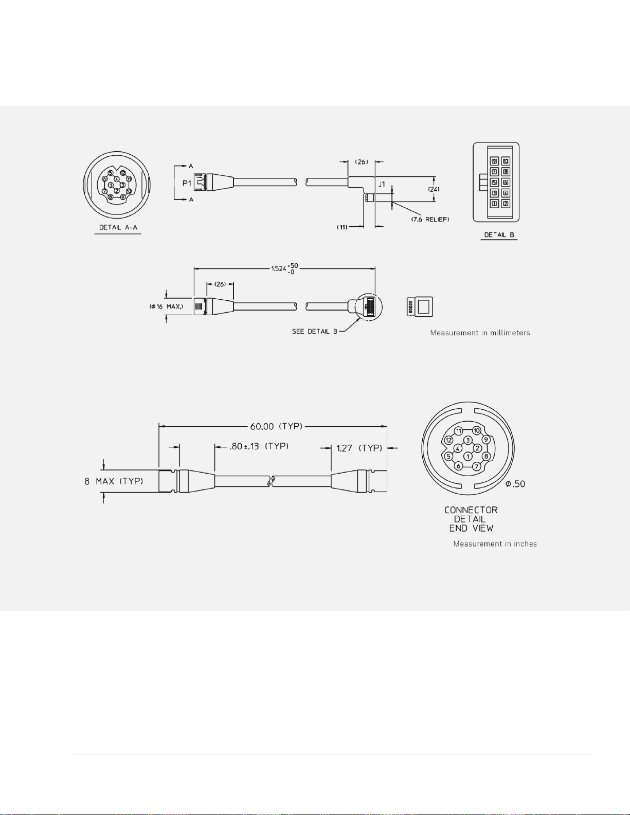
Find us at www.keysight.com Page 45
Interface Cable Drawings
Figure 1. Option 001 Viking connector to 10‑pin DIP connector
Figure 2. Option 201 Viking connector to 12‑pin conductor cable, bare wire
Page 46
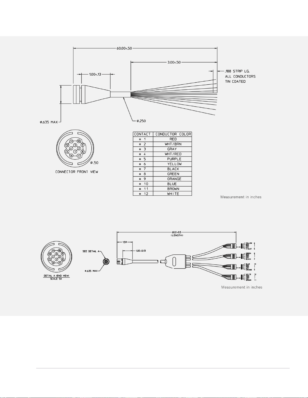
Find us at www.keysight.com Page 46
Figure 3. Option 201 Viking connector to 12‑pin conductor cable, bare wire
Figure 4. Option 301 Viking connector to ribbon cables
Page 47
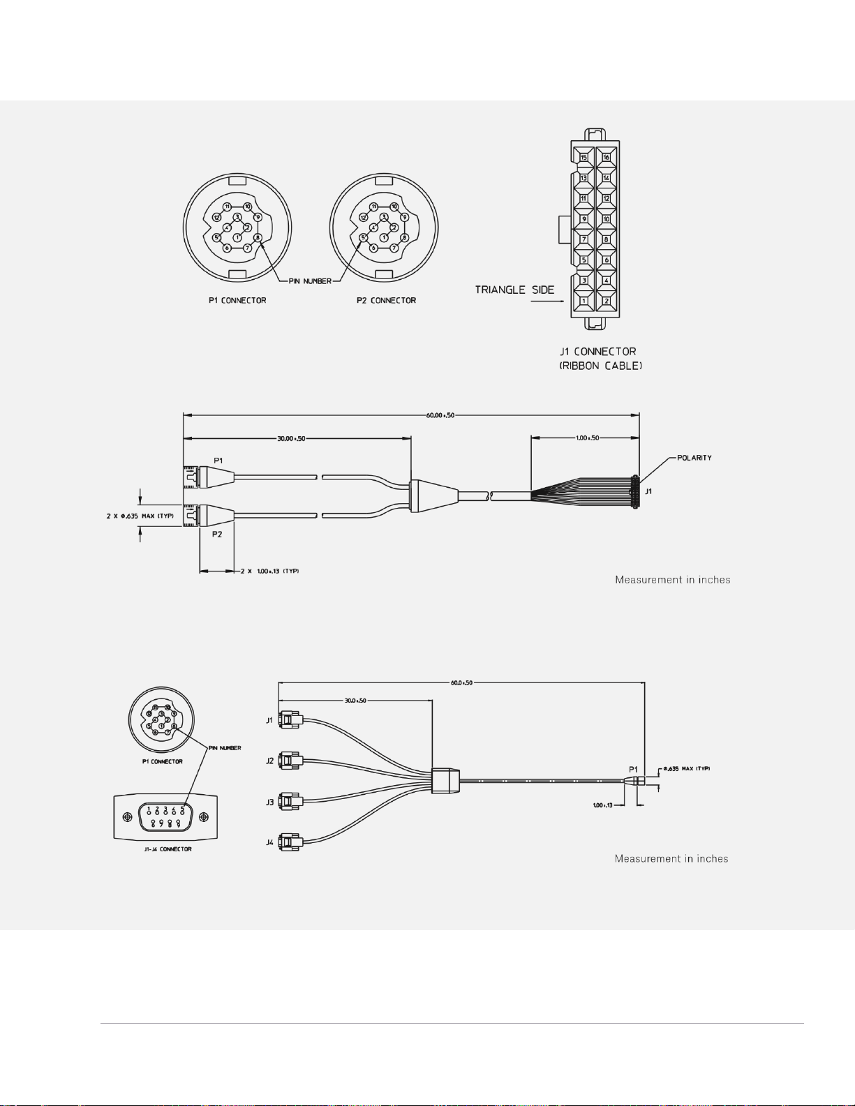
Find us at www.keysight.com Page 47
Figure 5. Option 401 Dual-viking connector 16‑pin DIP
Figure 6. Option 501 Viking connector to (4) 9‑pin Dsub connectors
Connector
Page 48

Find us at www.keysight.com Page 48
Figure 7. Option 601 Viking connector to 16‑pin DIP connector
Figure 8. Option 701 Viking connector to 14-pin DIP connector
Measurement in inches
Page 49
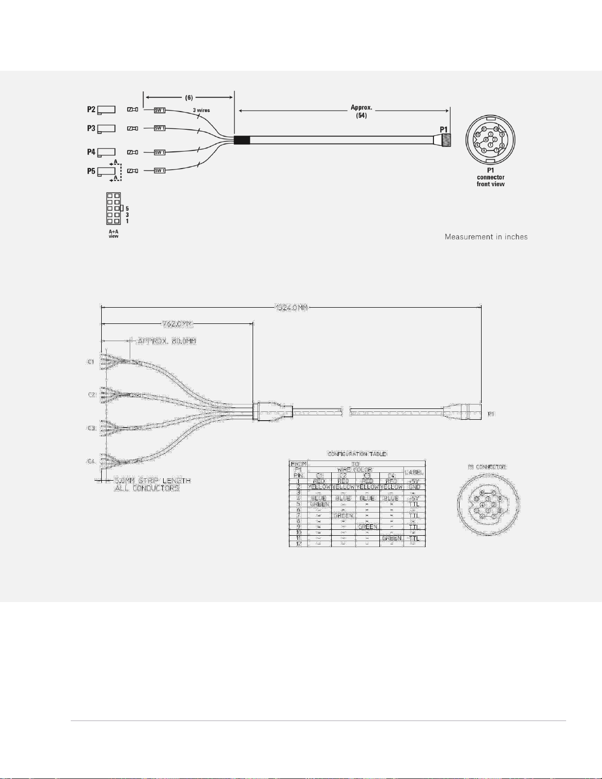
Find us at www.keysight.com Page 49
Figure 9. Option 801 Viking connector to (4) 10-pin DIP connector
Figure 10. Option 102 Viking connector to 4 cables with 4-conductor bare wires
Page 50
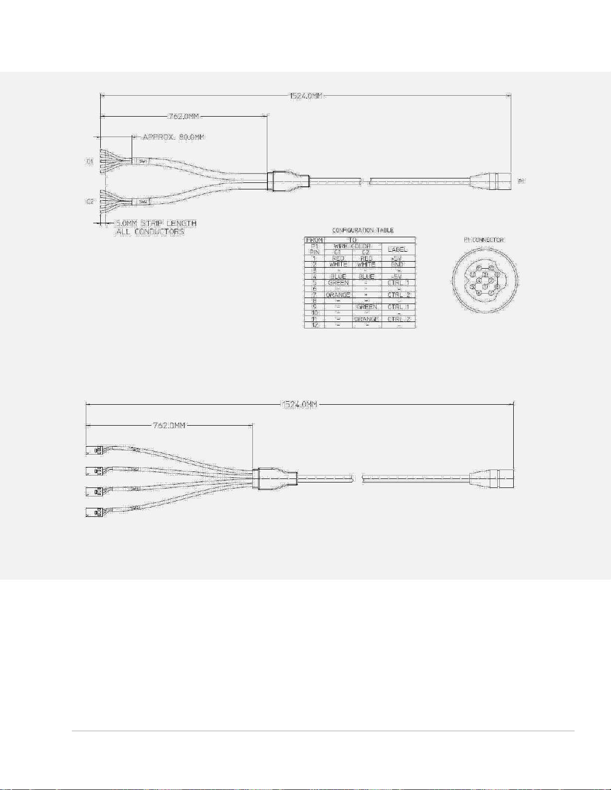
Find us at www.keysight.com Page 50
Figure 11. Option 103 Viking connector to 2 cables with 5-conductor bare wire
Figure 12. Option 104 Viking connector to 4 cables with 3-pin connector
Page 51
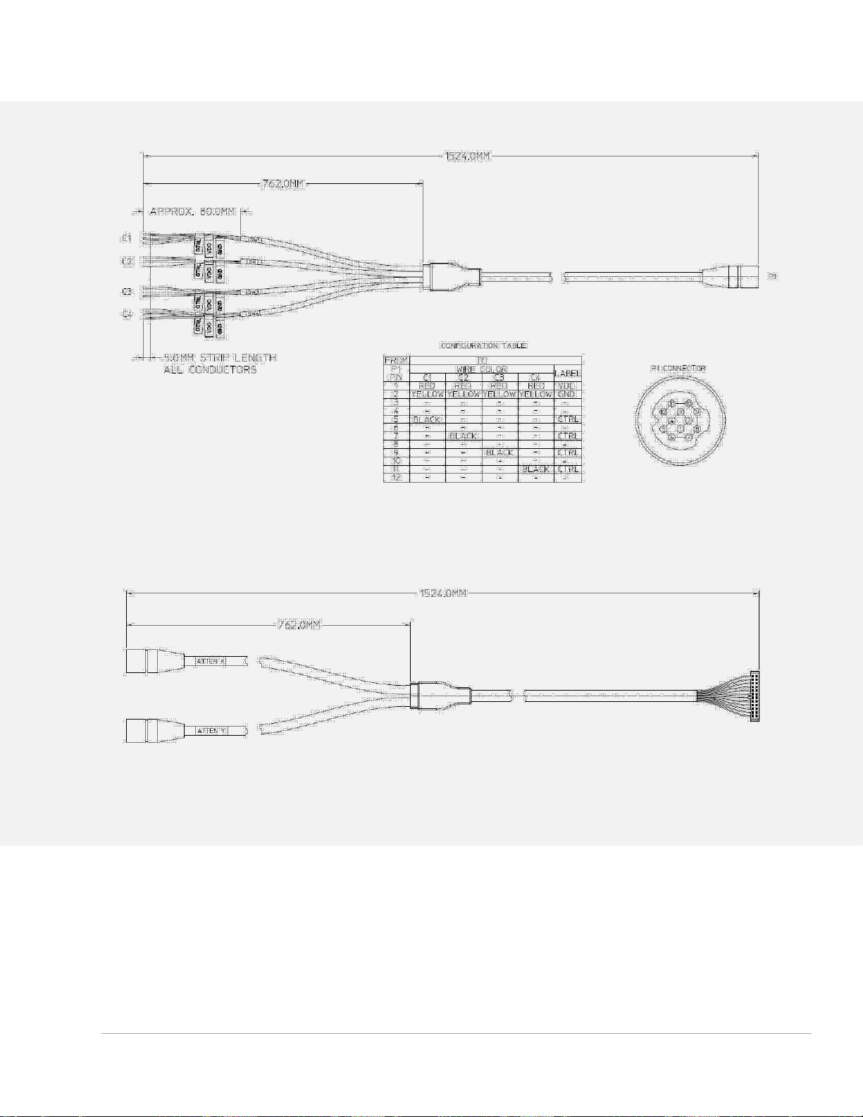
Find us at www.keysight.com Page 51
Figure 13. Option 105 Viking connector to 4 cables with 3-conductor bare wires
Figure 14. Option 106 Dual-viking connector to 24 pin DIP connector
Page 52
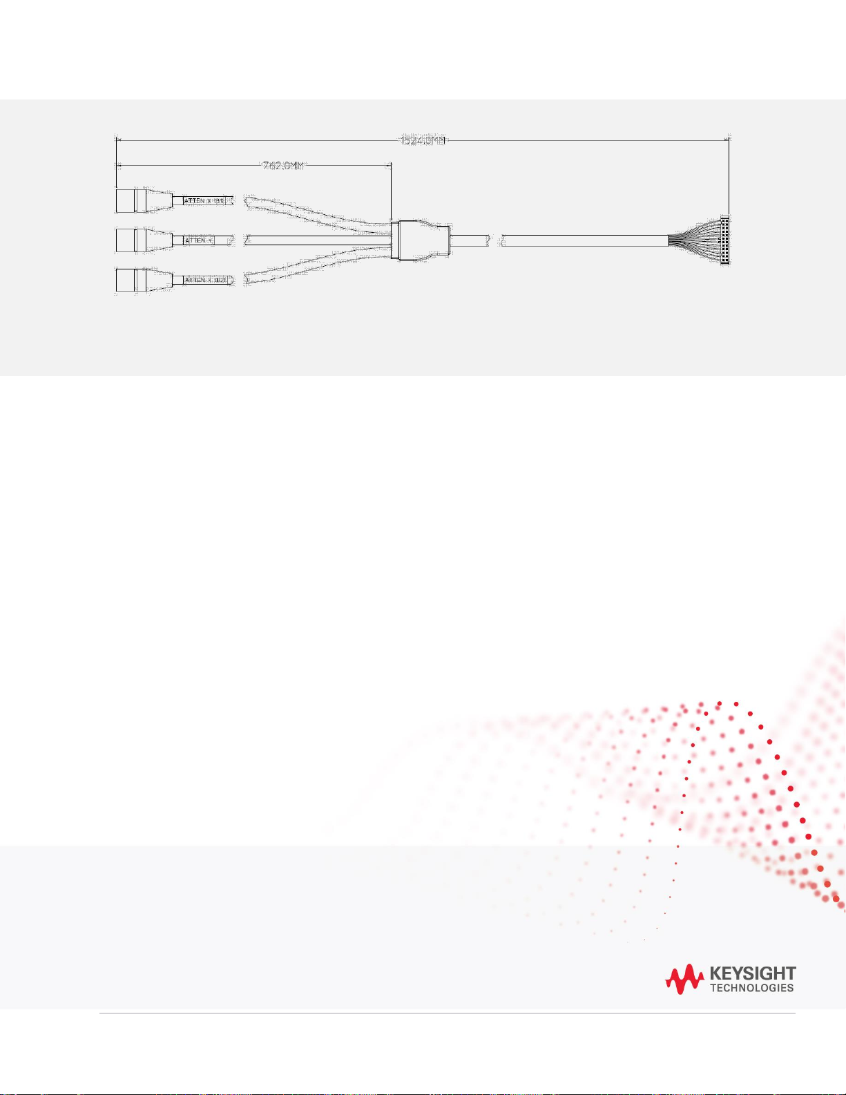
Find us at www.keysight.com Page 52
Thi s info rmatio n is subjec t to change with out no tice. © Ke ysight Tec hnologies, 2020 - 2021, Publis hed in USA , Oct ober 6, 20 21, 3 120-12 17.EN
Learn more at: www.keysight.com
For more information on Keysight Technologies’ products, applications, or services,
please contact your local Keysight office. The complete list is available at:
www.keysight.com/find/contactus
Weblink
•
www.keysight.com/find/11713
•
www.keysight.com/find/switches
•
www.keysight.com/find/attenuators
More RF and Microwave Test Accessories
For selection of more than 300 models of various type of RF and microwave test accessories with
operating frequency up to 110 GHz. Go to: www.keysight.com/find/mta
Figure 15. Option 107 Triple-viking connector to 24 pin DIP connector
 Loading...