

Page 1
KEYKING GROUP LIMITED
User Manual
Thank you for selecting Keyking products. Please read this manual thoroughly before using.
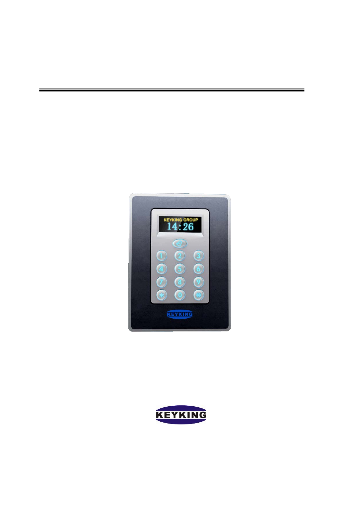
TA7003NT Time & Attendance Standalone
Page 2

K E YK ING GR O UP LIMI TE D TA7003NT User Manual(V1.0)
Index
................................................................................................................................................................................
Chapter1 Introduction .......................................................................................................................................... 3
1.1 Summary ................................................................................................................................................ 3
1.2 Features .................................................................................................................................................. 4
1.3 Application Mode ................................................................................................................................... 5
Chapter2 Wiri ng Diagram .................................................................................................................................... 7
2.1 TA7003N T Appearance .......................................................................................................................... 7
2.2 Wiring Diagram ...................................................................................................................................... 8
2.3 Lock Wiring Diagram ........................................................................................................................... 10
2.4 RS485 Net Bus ...................................................................................................................................... 11
2.5 TCP/IP Network .................................................................................................................................... 11
Chapter3 Instructions ......................................................................................................................................... 14
3.1 Clock Configuration ............................................................................................................................. 15
3.1.1 Edit Time ................................................................................................................................... 15
3.1. 2 Edit Alarm ................................................................................................................................ 15
3.2 Card Configuration ............................................................................................................................... 16
3.2. 1 Add Card .................................................................................................................................. 16
3.2. 2 Delete Card ............................................................................................................................... 17
3.2.3 Del All Cards ............................................................................................................................. 17
3.3 System Configuration ........................................................................................................................... 18
3.3.1 Language Setting ....................................................................................................................... 18
3.3.2 Menu Password ......................................................................................................................... 19
3.3.3 Reader Settings .......................................................................................................................... 19
3.3.4 System Info Configuration ........................................................................................................ 20
3.4 Delete ................................................................................................................................................... 22
3.4.1 Clear Event ................................................................................................................................ 22
3.4.2 Clear Card ................................................................................................................................. 22
3.4.3 Door Parameter Initialize .......................................................................................................... 23
3.4.4 Clear All .................................................................................................................................... 23
3.5 Door Open Mode .................................................................................................................................. 23
Chapter 4 Installation ......................................................................................................................................... 25
4.1 In the Wall ............................................................................................................................................ 25
4.2 On the Wall ........................................................................................................................................... 26
4.3 Without Installation Box ...................................................................................................................... 27
Chapter 5 FAQ ................................................................................................................................................... 28
Page 2 of 29
Page 3
K E YK ING GR O UP LIMITED TA7003NT User Manual(V1.0)
Chapter1 Introduction
1.1 Summary
TA7003NT is a new outstanding T&A standalone controller with OLED screen developed by
KEYKING. When TA7003NT works with a fingerprint reader as T&A controller, employees
need to press their finger on the reader(who has b een authorized) to complete attendance. The
OLED screen will display time and staff ID info. This system greatly improved the T&A
simplicity and offered cost saving on traditional tags. When TA7003NT works as an access
controller, the traditional ke y is no longer need ed, employees can enter their speci al space by
flashing authorized cards. TA7003NT can by itself control a door, both in and out, at least one
reader is needed for on e side, and the other side can be controlled either by a reader o r a Rex
Button. This system provides a more convenient and secured acc ess envi ron ment, it als o mak es
it possible for managers to verify the attendance in time. TA7003NT is compatible with a big
range of applications including, building management, enterprise management, government,
military and prison.
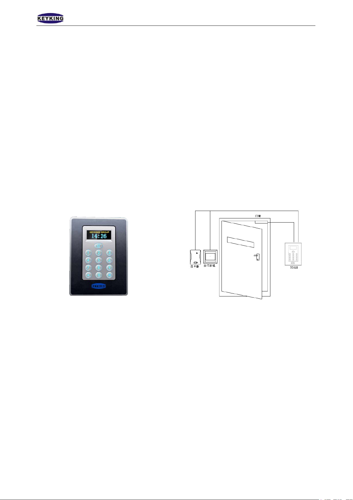
TA7003NT Appearance
Model Definition:
TA7003NT/E------Built in EM Card Reader
TA7003NT/H------Built in HID Card Reader;
TA7003NT/U------Built in Mifare\CPU Card Reader;
Supported Card Type:
E:EM Card; Exp EM4100, TK4100 Series.
H:HID Card; Exp: 1326、1386 Series.
U:FM1208 CPU Card,Philips S50, Mifare-1 Compatible
TA7003NT Diagram
Page 3 of 29
Page 4

K E YK ING GR O UP LIMITED TA7003NT User Manual(V1.0)
1.2 Features
1. TA7003NT is a new generation product of high v alue which has integrated keypad, text
display, single door control and T&A. Its 3 flexible uses are as below.
T&A:TA7003NT can directly communicate with host PC via RS485 or TCP/IP
which managed by software AccessWatch3000.
Single Door Controller:TA7003NT can work as a access controller with
external readers for single door In/Out control.
Wiegand Reader With OLED Display:TA7003NT can work as a reader
which outputs wiegand26 or wiegand34 signal while the OLED screen shows
time and card number.
2. 1 Rex Button output, 1 magnetic input, 1 Wiegand 26/34 input/output(both IC, ID card
compatible, IC card read s serial number), 2 auxiliary inputs, 2 relay outputs, 1 RS485
interface, 1 door bell interface.
3. Can connect with external Wiegand26/34 reader(keypad reader included), Entrance/exit
can be controlled by “Card/PIN” or “Card + PIN”.
4. Customized OLED LOGO display, En glish menu with backlight. Showing the name and
card number when reading a card.
5. Network (127 for RS485, no limit for TCP/IP), offline mode available but customers
need to configure via the keypad before work offline.
6. The system can register 100 pcs Wiegand26/34 RFID cards and store 200000 events
when it's offline mode. When it comes to online mode, all data can be uploaded to host
PC and 30000 cards can be registered.
7. 8 sorts of alarm clock for 9 to 5.
8. System can assign different time groups for 124 user departments within 365 days. Each
door can be authorized with 31 time groups, 7 holiday groups. Any days of a year can be
the composition of a holiday group. Anyone who has no access authority of holiday
group will not be entrance allowed. The system will inform all controllers to adjust time
schedule if the date in the 2 temporary time group triggered. The system will
automatically sync the clock to ensure accurate event alert.
9. Remote door control available, multiple incidents alarm functions, exp as door open
timeout, door close timeout, intrusion alarm, duress alarm, tamper alarm and fire alarm.
Page 4 of 29
Page 5

K E YK ING GR O UP LIMITED TA7003NT User Manual(V1.0)
10. Specifications
Work Mode:
Card Mode;
PIN Mode;
Card/PIN Mode;
Card + PIN(interval time 8 sec)
Supported User Number:30000 pcs
PIN User Numb er :10
Communicate Frequency:
125KHZ:
E: EM;
13.56MHZ:
M: Mifare;
U:CPU
Read Range:3-15CM
Outputs:NC/NO,30VDC,5A
Power Supply:12VDC+10% ,
Dimension:117mm (H) x 86mm (W) x 22mm (D)
。
200MA
1.3 Application Mode
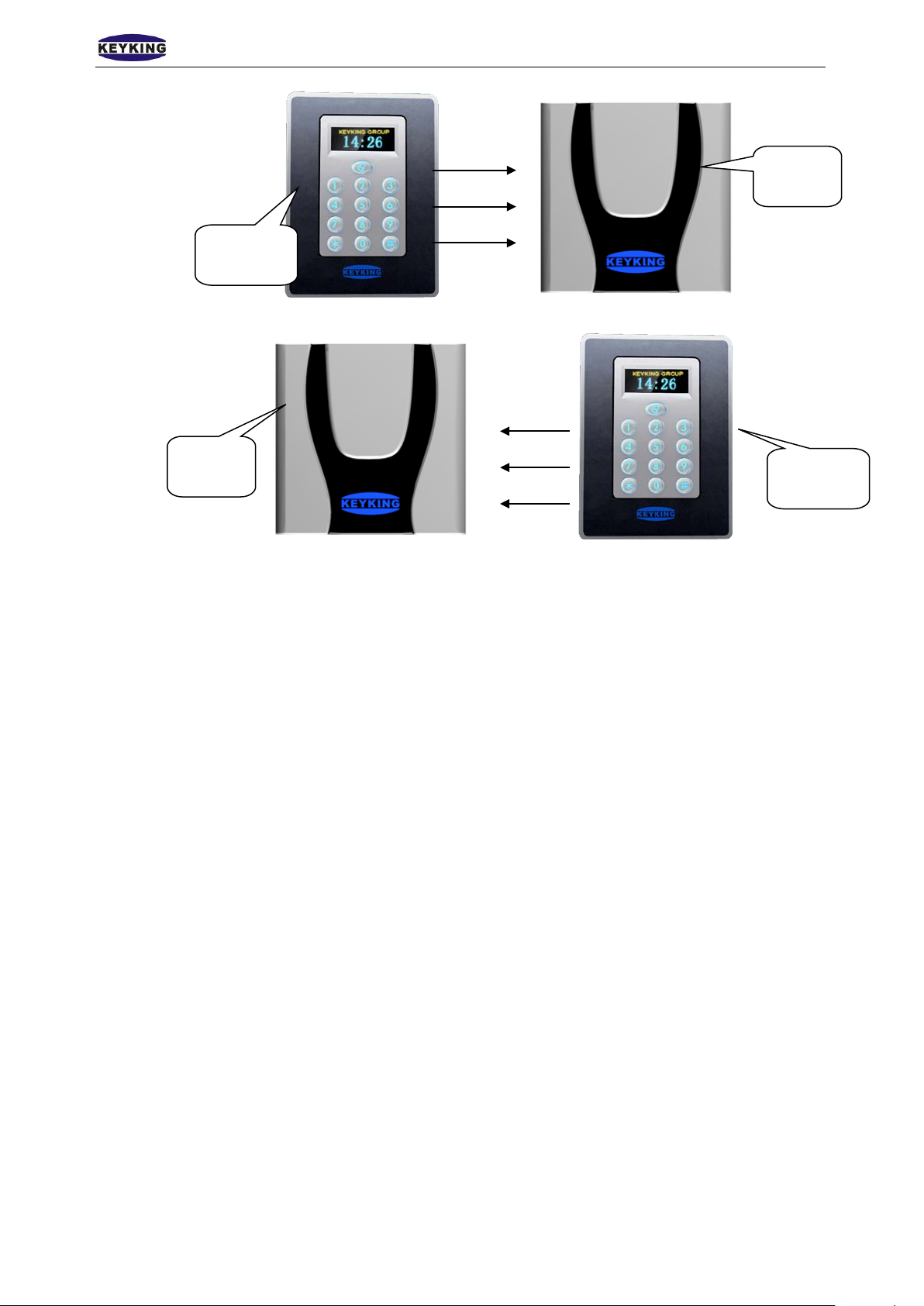
3 Application Modes:
Standalone
Outdoor external reader, indoor TA7003NT
Page 5 of 29
Page 6
K E YK ING GR O UP LIMITED TA7003NT User Manual(V1.0)
TA7003N
reader
Reader
TA7003N
Outdoor
Indoor
Indoor external reader, outdoor TA7003NT
Indoor
Outdoor
Page 6 of 29
Page 7
K E YK ING GR O UP LIMITED TA7003NT User Manual(V1.0)
3 3 Numeral 3
9 9 Numeral 9
Backlight
Clock
Company Logo
Chapter2 Wiring Diagram
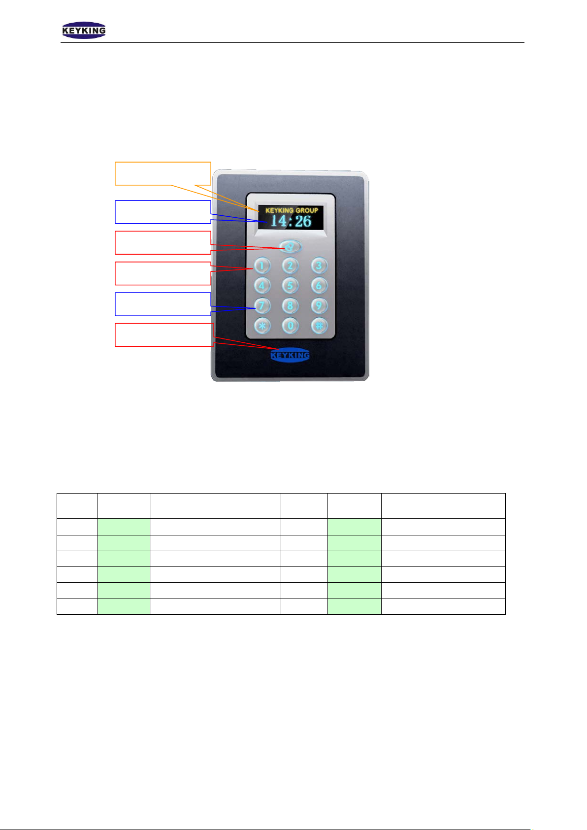
2.1 TA7003NT Appearance
Door bell
Keypad
LED (Green&Blue)
Figure 2-1
LED:
Blue LED:Power indicator
Green LED:Sensor indicator(Relay turned on indicator)
Keypad:
NO. Key Description NO. Key Description
1 1 Numeral 1 7 7 Numeral 7
2 2 Numeral 2 8 8 Numeral 8
4 4 Numeral 4 10 0 Numeral 0
5 5 Numeral 5 1 * Cancel / Start
6 6 Numeral 6 12 # Enter / Confirm
Page 7 of 29
Page 8
K E YK ING GR O UP LIMITED TA7003NT User Manual(V1.0)
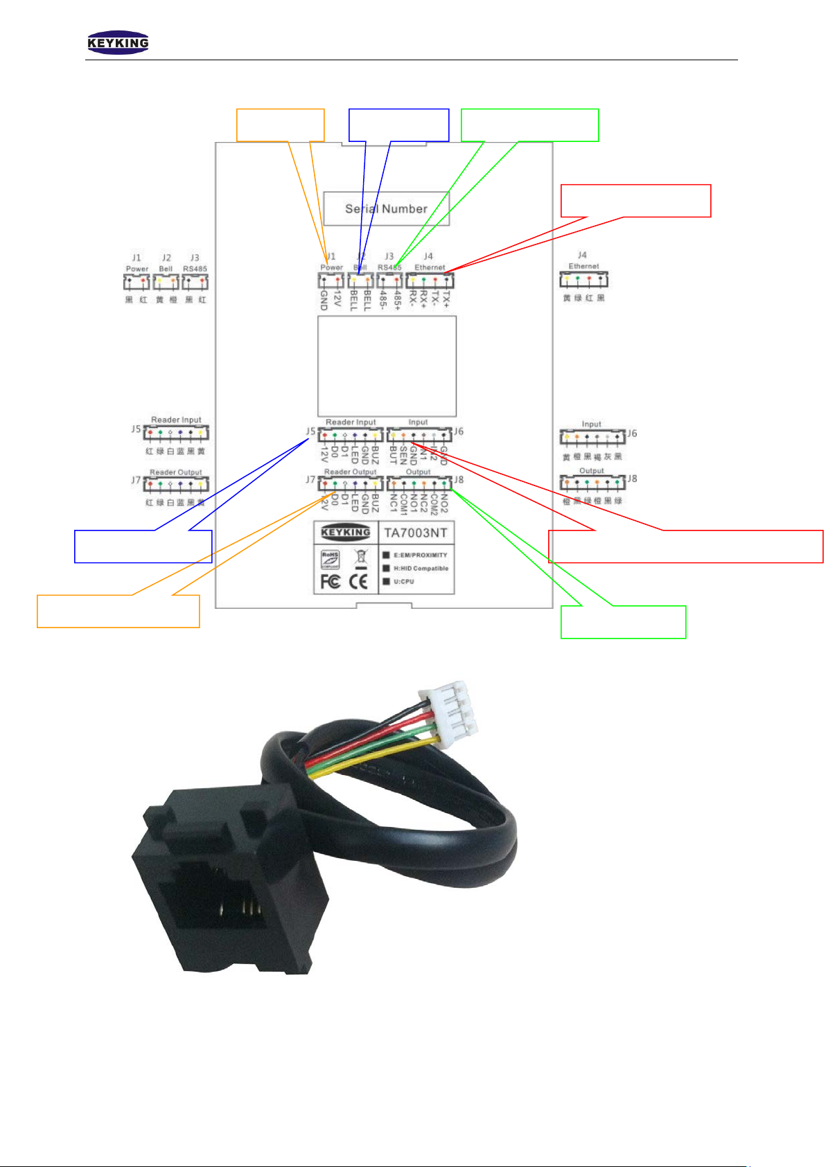
J4:TCP/IP interface
J8:Relay output
2.2 Wiring Diagram
J1:Power
J2:Door bell
J3:RS485 interface
J7:Reader signal output
TCP/IP interface, as shown below:
Figure 2-2 Backside
J6:Megnetic,Rex Button, Auxiliary output J5:Reader interface
Figure 2-3
Page 8 of 29
Page 9
K E YK ING GR O UP LIMITED TA7003NT User Manual(V1.0)
Icon NO
1 GND
J1
J2
J3
J4
J5
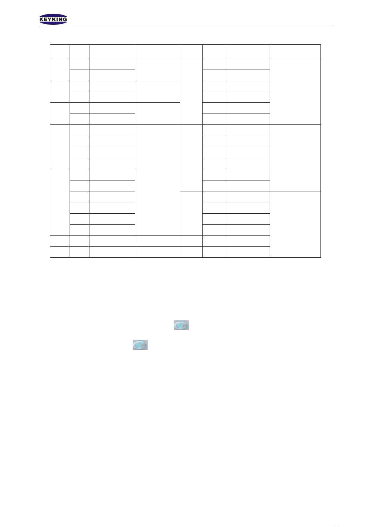
Wiring Description:
2 12V 18 SEN
3 BELL
4 BELL 20 IN1
5 4856 485+ 22 GND
7 RX8 RX+ 24 D0
9 TX- 25 D1
10 TX+ 26 LED
11 12V
12 D0 28 BUZ
13 D1
14 LED 30 COM1
15 GND 31 NO1
16 BUZ 32 NC2
J1: Power Supply
12V:DC 12V Positive
GND:Ground
J2: Door Bell
Connection Definition
Power supply
Door bell
485 interface
TCP/IP
interface
External
reader
interface
Icon NO
17 BUT
J6
J7
J8
2-1
19 GND
21 IN2
23 12V
27 GND
29 NC1
33 COM2
34 NO2
Connection Definition
Magnetic, Rex
Button,
Auxiliary output
Reader signal
output
Relay output
Normally, J2 outputs open signal if is not pressed.
If door bell is used,
is pressed and J2 will outputs close signal to drive door bell rings.
J3: 485 Interfaces
An IC232 or RS485HUB is needed to connect host PC.
Customer can set all configurations when it’s connected to host PC. Moreover user
authorization and exporting card events can also be done via AccessWatch3000.
J4: TCP/IP Interfaces
Available to use a switch or directly connect to host PC via Ethernet port.
Customer can set all configurations when it’s connected to host PC. Moreover user
authorization and exporting card events can also be done via AccessWatch3000.
J5: External Reader Interfaces
12V:External reader power supply (Positive)
D0:Wiegand input
D1:Wiegand output
LED: Indicator connector
GND:Ground.
Page 9 of 29
Page 10

K E YK ING GR O UP LIMITED TA7003NT User Manual(V1.0)
BUZ: Buzzer connector
J6: Magnetic Switch, Rex Button, Auxiliary Input
BUT: Rex Button connector(GND for the other side).
SEN: Magnetic switch connector(GND for the other side).
GND: Negative(Public side).
IN1: Auxiliary input 1.
IN2: Auxiliary input 2.
J7: Built-in Reader Output
12V:Positive
D0:Wiegand output 0
D1:Wiegand output 1
LED: Indicator connector
GND:Negative(Public side).
BUZ:Buzzer connector
J8: Electronic Lock、Relay Output
Based on customized lock model.
2.3 Lock Wiring Diagram
J4: Relay Output(Lock Control)
As shown below.
Figure 2-4 Electronic Strike Lock
Figure 2-5 Magnetic Lock(Fail safe)
Page 10 of 29
Page 11
K E YK ING GR O UP LIMITED TA7003NT User Manual(V1.0)
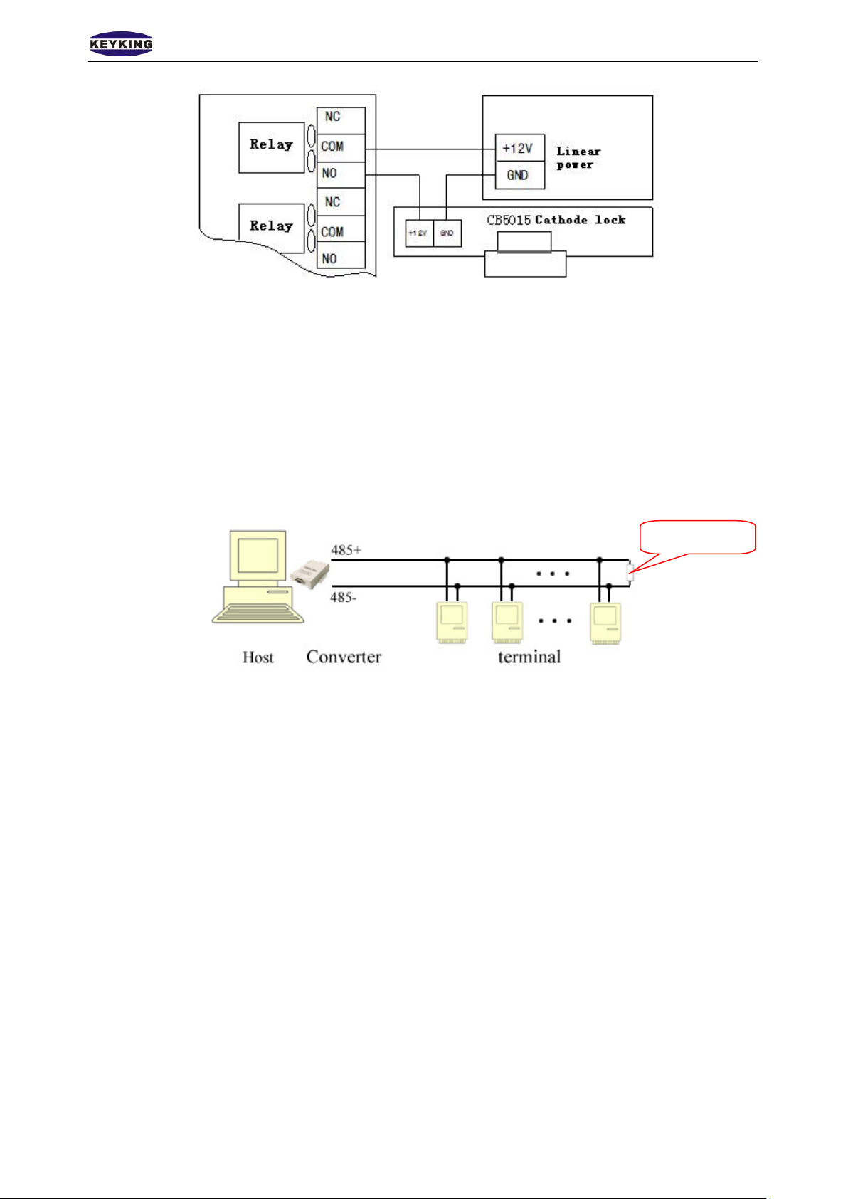
Twisted-pair:Twisted-pair are used to connect controller to controller. No GND is needed.
Series connection:Terminals are connecting via series connection. A multi-bus RS485HUB is
needed if customer needs parallel connection.
RS485 Single Point Ground:If controller transmission line is with shielding or needs ground
line, then all controllers’ transmission line can be grounded in either controller. Please
note do not gather all metal side to the GND of controller.
Terminal Resistance:Series connected at the end of the circuit.
Figure 2-6 Cathode lock(Fail secure)
2.4 RS485 Net Bus
TA7003NT can communicate via half-duplex RS485 bus, up to 1200m communication distance. Terminals
use series connection.
Please make sure power supply is in off state before do wiring. This helps to avoid any damage maybe caused
to the device.
120Ω
Figure 2-7
2.5 TCP/IP Network
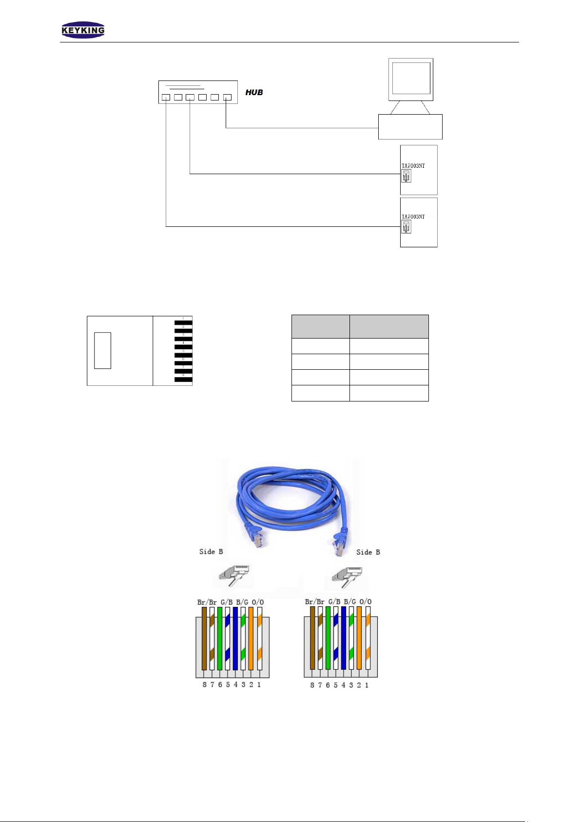
TA7003NT TCP/IP network
Page 11 of 29
Page 12
K E YK ING GR O UP LIMITED TA7003NT User Manual(V1.0)
3
RX+
Figure 2-8
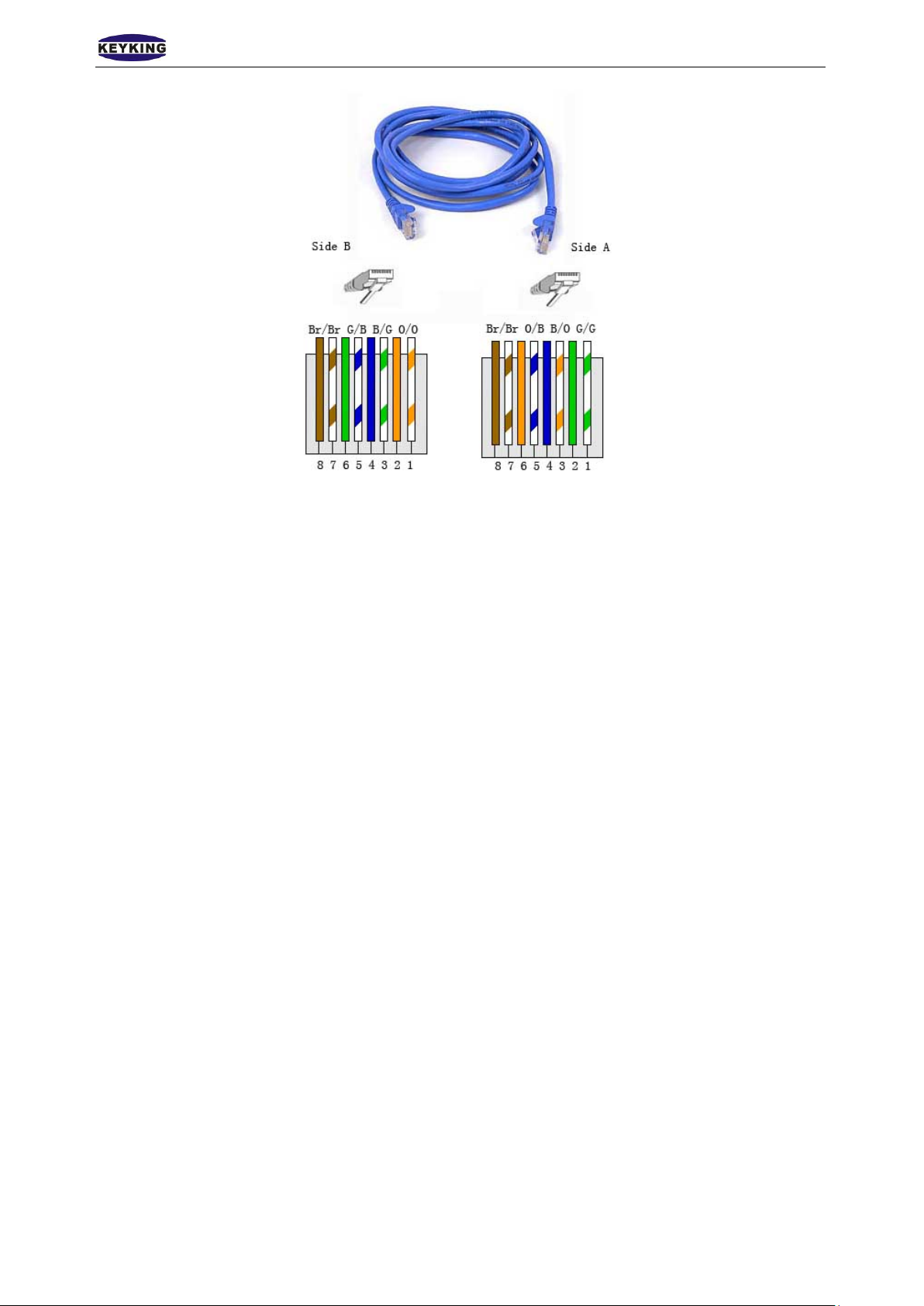
TCP/IP crystal head
Figure 2-9
Normal net cable(to switch)
8←1
RJ45 NO. Difination
1 TX+
2 TX-
6 RX-
Sheet 2-2
8←1
图 2-10
Crossed cable(to PC)
Page 12 of 29
Page 13
K E YK ING GR O UP LIMITED TA7003NT User Manual(V1.0)
8←1
8←1
Figure 2-11
Page 13 of 29
Page 14
K E YK ING GR O UP LIMITED TA7003NT User Manual(V1.0)
Chapter3 Instructions
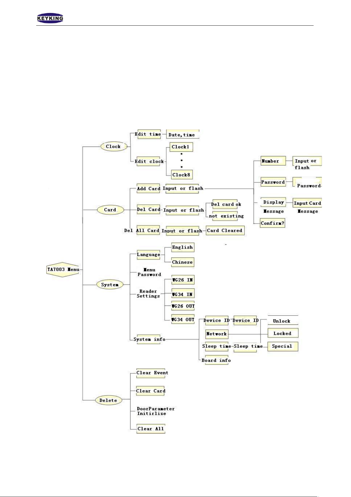
User Management、PIN management、Work mode and Time set are configured in the manage menu. Menu
structure is shown below.
Press * 39 # to enter manage menu when idle. In the main menu, “*” works as “cancel”, “#” works as
“confirm”, “3” works as “Up”, ”9” works as “down”.
Page 14 of 29
Page 15
K E YK ING GR O UP LIMITED TA7003NT User Manual(V1.0)
3.1 Clock Configuration
3.1.1 Edit Time
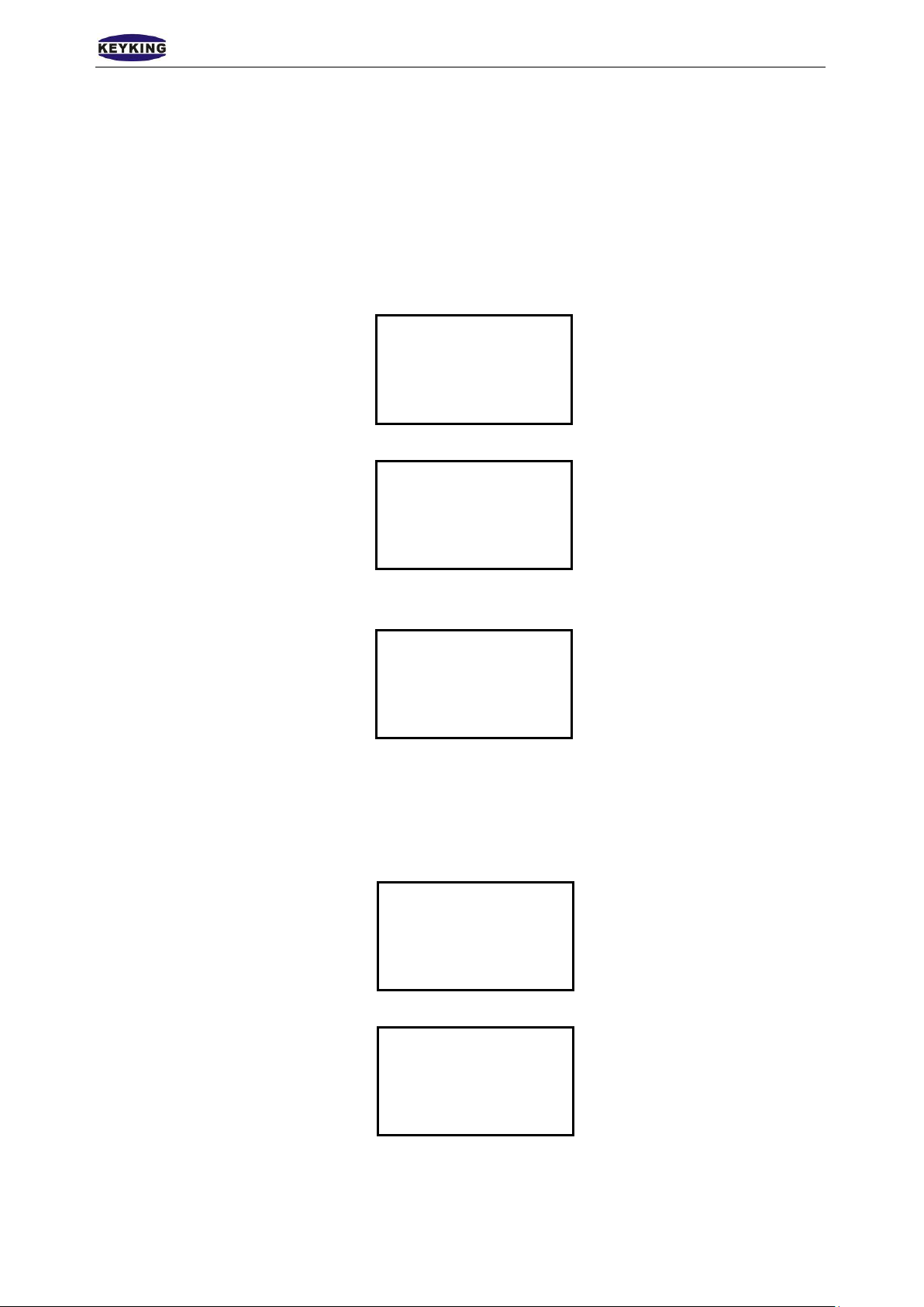
1. Press * 39 # to enter manage menu when idle. In the main menu, “*” works as “cancel”, “#”
works as “confirm”, “3” works as “Up”, ”9” works as “down”.
Clock ◆
Cards
System
Delete
2. Press “#” to edit time.
Edit time ◆
Edit alarm
3. Use keypad to set the current time, press “#” to confirm.
3.1. 2 Edit Alarm
1. Press * 39 # to enter manage menu when idle.
2. Press # to enter Clock menu, press 9 to select edit alarm.
Edit time
**-**-** **:**
Time format:Year-Month-Day Hour:Minute
Clock ◆
Cards
System
Delete
Edit time ◆
Edit alarm
◆
2. Press # to enter edit alarm.
Page 15 of 29
Page 16
K E YK ING GR O UP LIMITED TA7003NT User Manual(V1.0)
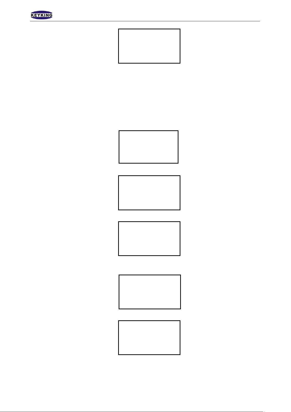
Delete
Alarm1x ◆
Alarm2x
……
Alarm8x
Press # to select a alarm to be edited. Use keypad to enter the alarm details.
3.2 Card Configuration
3.2. 1 Add Card
1. Use button 3 or 9 to select Cards when enter the manage menu.
Clock
Cards ◆
System
2. Use button 3 or 9 to select Add Card.
Add Card ◆
Del Card
Del All Card
3. Press # to enter register interface.
Input or Flash
0000000000
4. Input a ten digits number or flash the card you want to register on TA7003NT, the card number
will be read by TA7003NT automatically and shows up on the screen.
Input or Flash
0123456789
5. Press # to enter the next menu.
Card 0000000000 ◆
Password 0000
Disp Mess 00
Confirm?
Verify the card information and input the password if needed then select “Confirm?” and
press# to confirm. If customer wants to add another or more cards, please go back to step 3 and
repeat the process.
Page 16 of 29
Page 17
K E YK ING GR O UP LIMITED TA7003NT User Manual(V1.0)
Delete
3.2. 2 Delete Card
1. Use button 3 or 9 to select Cards when enter the manage menu.
Clock
Cards ◆
System
2. Use button 3 or 9 to select Del Card.
Add Card
Del Card ◆
Del All Card
3. Press # to enter delete card interface.
Input or Flash
0000000000
4. Input a ten digits number or flash the card you want to register on TA7003NT, the card number
will be read by TA7003NT automatically and shows up on the screen.
Input or Flash
0123456789
5. Press # to enter the next menu.
Del Card?
Note:When the screen shows Del Card OK, it means you have successfully deleted a registered card. If
customer wants to delete more cards, just continue flashing card and press # to confirm
deleting. There is no need to go back to step 2.
3.2.3 Del All Cards
Use Del All Cards to clear all cards.
1. Use button 3 or 9 to select Cards when enter the manage menu.
Page 17 of 29
Page 18
K E YK ING GR O UP LIMITED TA7003NT User Manual(V1.0)
Delete
Clock
Cards ◆
System
2. Use button 3 or 9 to select Del All Card
Add Card
Del Card
Del All Card ◆
3. Press # to enter Delete All Card interface.
Input or Flash
0000000000
4. Input a ten digits number or flash the card you want to register on TA7003NT, the card number
will be read by TA7003NT automatically and shows up on the screen.
5. Press # to enter the next menu.
3.3 System Configuration
3.3.1 Language Setting
TA7003NT support two languages. (English and Chinese)
1. Use button 3 or 9 to select System when enter the manage menu.
2. Press # to enter System interface.
Input or Flash
0123456789
Clock
Cards
System ◆
Delete
Language ◆
Menu Password
Reader Settings
System Info
3. Press # to enter language setting interface.
Page 18 of 29
Page 19
K E YK ING GR O UP LIMITED TA7003NT User Manual(V1.0)
——————
English× ◆
Chinese√
Use button 3 or 9 to select the language customer wanted. Press # to confirm.
3.3.2 Menu Password
There is no defaulted password, customer can set favored password. Steps:
1. Use button 3 or 9 to select System when enter the manage menu.
Clock
Cards
System ◆
Delete
2. Use button 3 or 9 to select Menu Password.
Language
Menu Password ◆
Reader Settings
System Info
3. Press # to enter Menu Password setting interface
New Password
Use the keypad to input 6 digits password and press # to confirm. User will have to input the
password if he wants to enter manage menu.
3.3.3 Reader Settings
1. Use button 3 or 9 to select System when enter the manage menu.
Clock
Cards
System ◆
Delete
2. Use button 3 or 9 to select Reader Settings.
Page 19 of 29
Page 20
K E YK ING GR O UP LIMITED TA7003NT User Manual(V1.0)
Language
Menu Password
Reader Settings ◆
System Info
3. Press # to enter Reader setting interface
WG26 IN√ ◆
WG34 IN×
WG26 OUT×
WG26 OUT×
Use button 3 or 9 to select reader Input/output format。
3.3.4 System Info Configuration
3.3.4.1 Device ID
1. Use button 3 or 9 to select System when enter the manage menu.
Clock
Cards
System ◆
Delete
2. Use button 3 or 9 to select System Info.
Language
Menu Password
Reader Settings
System Info ◆
3. Press # to enter System Info setting interface
Device ID ◆
Network
Sleep Time
Board Info
4. Use button 3 or 9 to select Device ID and press # to confirm.
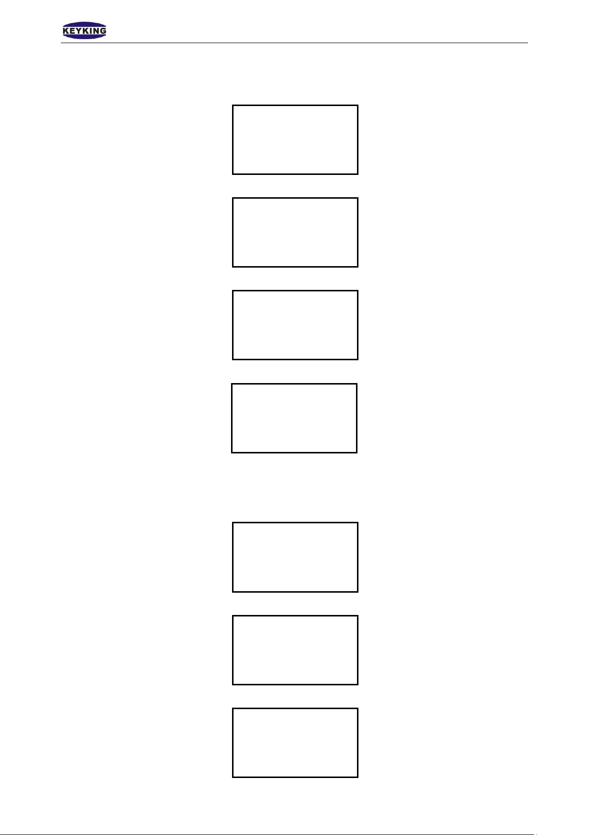
Device ID
001
Press # to confirm Device ID setting. Device ID must be set when using multiple TA7003NT
while it’s not necessary for standalone.
Page 20 of 29
Page 21
K E YK ING GR O UP LIMITED TA7003NT User Manual(V1.0)
3.3.4.2 Network Configuration
1. Use button 3 or 9 to select System when enter the manage menu.
Clock
Cards
System ◆
Delete
2. Use button 3 or 9 to select System Info.
Language
Menu Password
Reader Settings
System Info ◆
3. Press # to enter System Info setting interface
Device ID
Network ◆
Sleep Time
Board Info
4. Use button 3 or 9 to select Network and press # to confirm.
Unlock√ ◆
Locked×
Special×
Use button 3 or 9 to select network mode. The defaulted IP address is 10.1.1.10
3.3.4.3 Sleep Time
1. Use button 3 or 9 to select System when enter the manage menu.
Clock
Cards
System ◆
Delete
2. Use button 3 or 9 to select System Info.
Language
Menu Password
Reader Settings
System Info ◆
3. Press # to enter System Info setting interface.
Device ID
Network
Sleep Time ◆
Board Info
Page 21 of 29
Page 22
K E YK ING GR O UP LIMITED TA7003NT User Manual(V1.0)
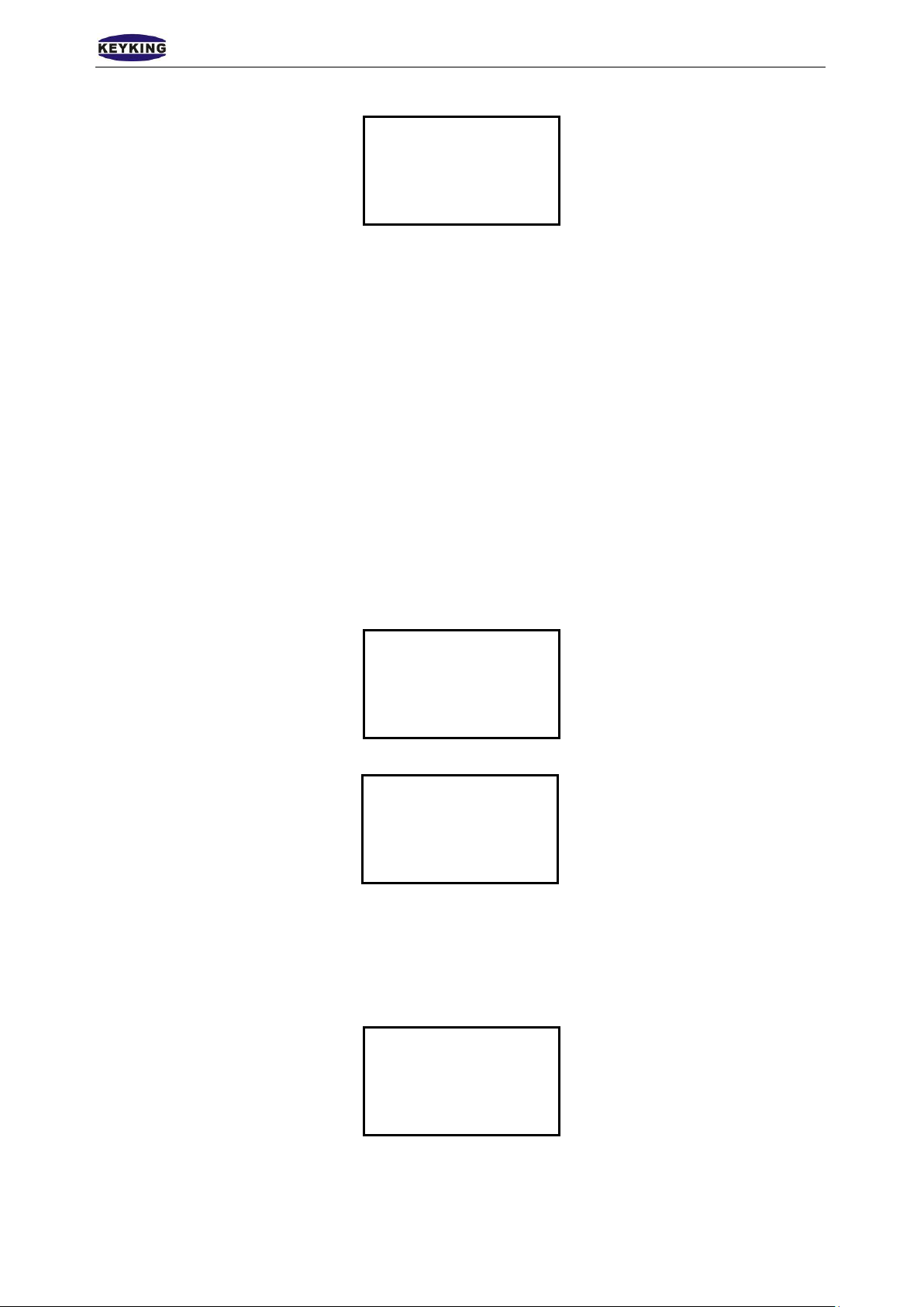
4. Use button 3 or 9 to select Sleep Time and press # to confirm.
Sleep Time
020 Sec
Use keypad to input sleep time (sec), press # to confirm.
3.3.4.4 Board Info
Use to check TA7003NT version and production date.
Example:
Version:.TA7003 Ver 03.00
Date:20100415(Programmed date 2010-4-15)
IP Address:192.168.1.100
MAC Address: 0010F0040413
3.4 Delete
3.4.1 Clear Event
1. Use button 3 or 9 to select Delete when enter the manage menu.
Clock
Cards
System
Delete ◆
2. Press # to enter Delete interface.
Clear Event ◆
Clear Card
DoorPara Init
Clear All
Press # again to confirm Clear Event.
3.4.2 Clear Card
1. Use button 3 or 9 to select Delete when enter the manage menu.
Clock
Cards
System
Delete ◆
2. Press # to enter Delete interface and use button 3 or 9 to select Clear Card.
Page 22 of 29
Page 23
K E YK ING GR O UP LIMITED TA7003NT User Manual(V1.0)
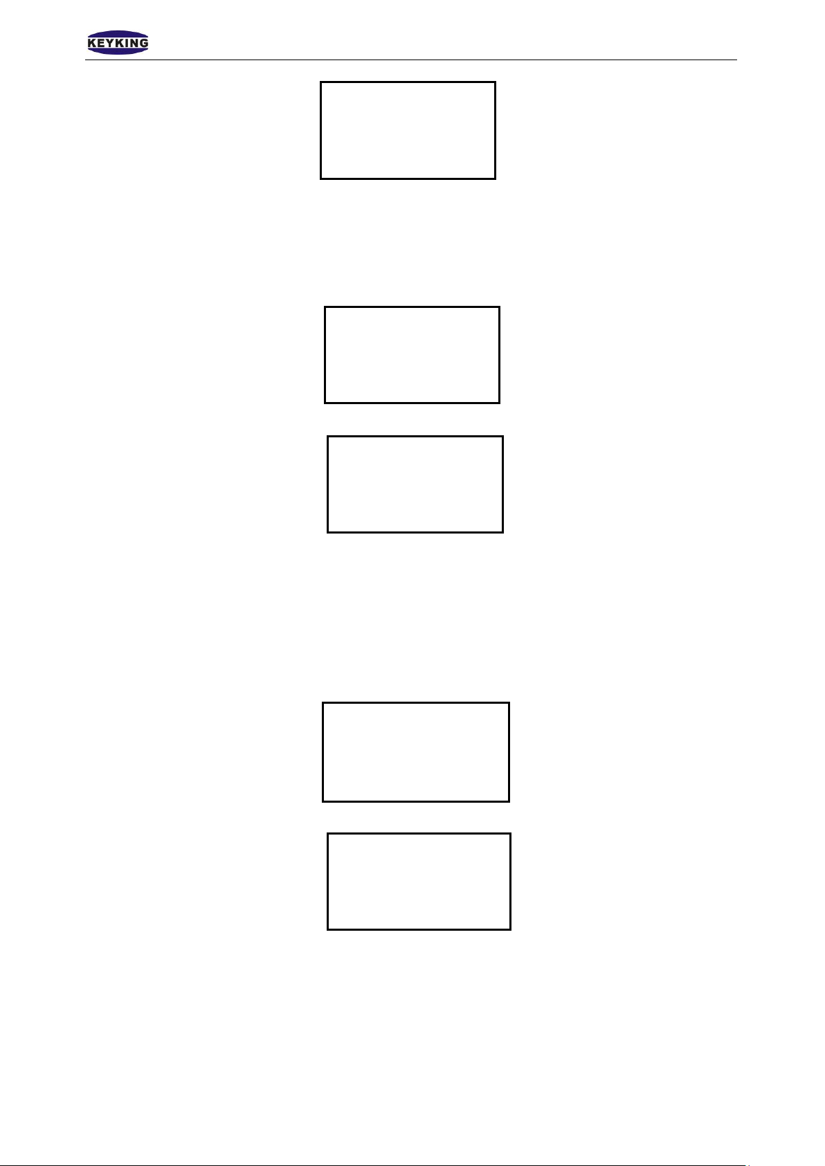
Clear All ◆
Clear All
Clear All
Clear Event
Clear Card ◆
DoorPara Init
Press # again to confirm Clear Card.
3.4.3 Door Parameter Initi ali ze
1. Use button 3 or 9 to select Delete when enter the manage menu.
Clock
Cards
System
Delete ◆
2. Press # to enter Delete interface and use button 3 or 9 to select DoorPara Init.
Clear Event
Clear Card
DoorPara Init ◆
Press # again to confirm Door Parameter Initialize.
3.4.4 Clear All
If somehow the entire data, time, password or work mode is messed up, we can use Clear All to
reset the controller to defaulted state.
1. Use button 3 or 9 to select Delete when enter the manage menu.
Clock
Cards
System
Delete ◆
2. Press # to enter Delete interface and use button 3 or 9 to select Clear All.
Clear Event
Clear Card
DoorPara Init
Press # again to confirm Clear All and all configuration will be set to defaulted.
3.5 Door Open Mode
1 By Card
Steps: 1. Register your card by using Add Card in the manage menu. 2. Flash the card on TA7003NT.
(3-10cm read range) 3. The screen shows card number, owner name. 4. Relay responds, door open.N
Page 23 of 29
Page 24

K E YK ING GR O UP LIMITED TA7003NT User Manual(V1.0)
Please note that if the card is not registered, the TA7003NT will beep three short sounds and shows
invalid card on the screen. Door will stay closed.
2 By card + PIN
Steps: 1. Register your card and set password by using Add Card in the manage menu. Password is
limited to 4 digits. 2. Flash the card on TA 7003NT. (3-10cm read range) Input your password after
a long beep sound and press # to confirm. Password should be inputted in 8 seconds after flashing
your card.
Page 24 of 29
Page 25
K E YK ING GR O UP LIMITED TA7003NT User Manual(V1.0)
Chapter 4 Installation
Steps:
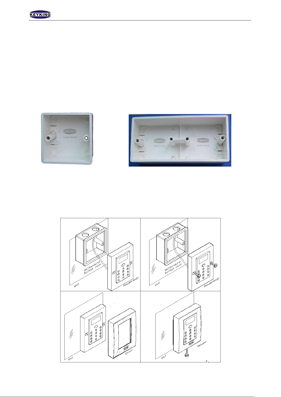
4.1 In the Wall
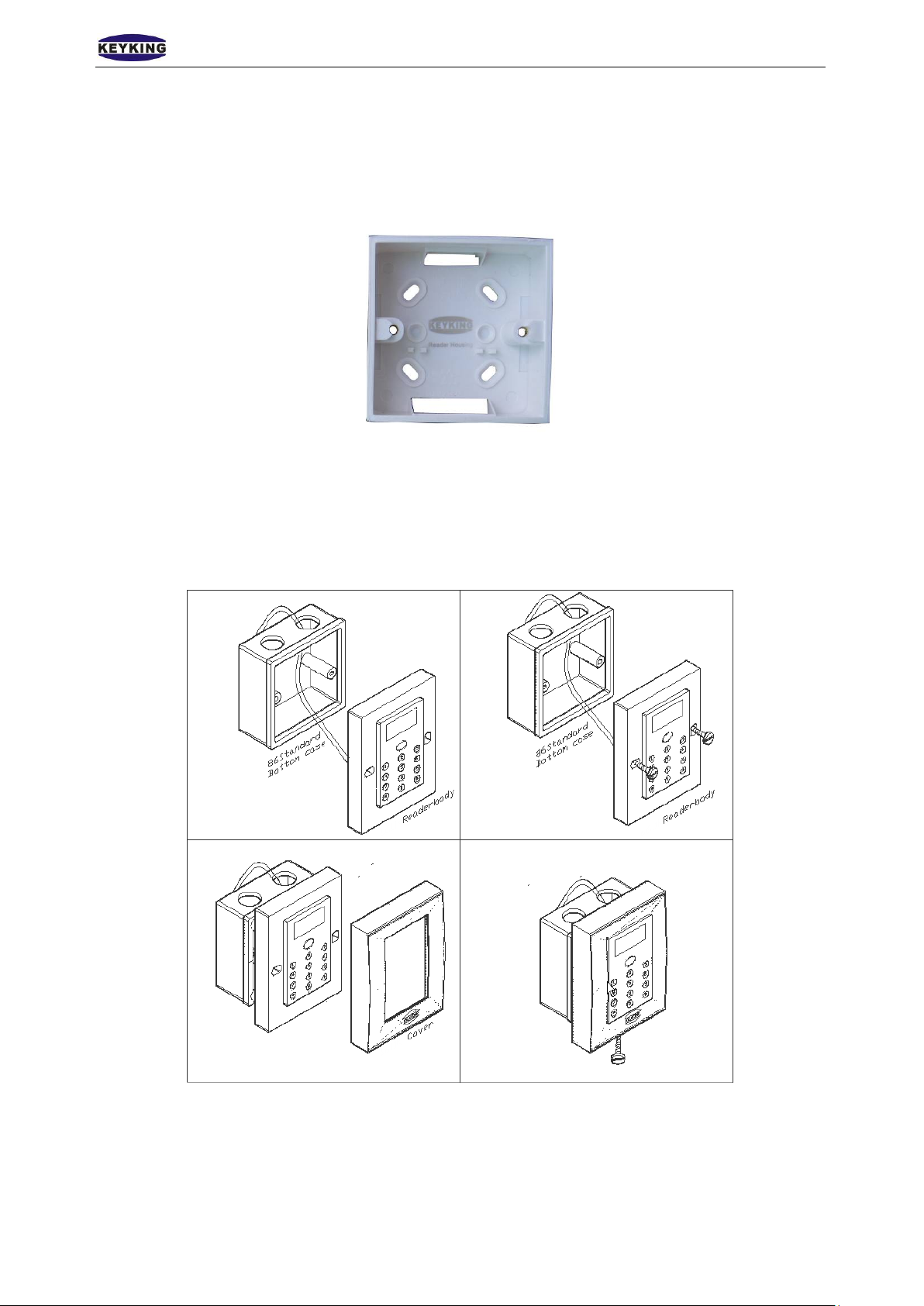
1. Use installation box: Drill a hole on the wall (size:86x86mm) where you want to install your reader. Then
install the installation box in the hole.
a). Installation box (Standard 86 box, single) b). Installation box (double)
2. Wiring: Design the wiring between reader and controller, then process wiring.
3. Connection: Please refer to chapter 2 of the connections.
4. Fix reader on the box:Use 2 M6*30 screws to fix reader on the box.
5. Cover up.
Page 25 of 29
Page 26
K E YK ING GR O UP LIMITED TA7003NT User Manual(V1.0)
4.2 On the Wall
1. Use installation box: Use 4 screws to fix standard 86 box on the wall.
a). Installation box (Standard 86 box, single)
2. Wiring: Design the wiring between reader and control ler , then process wiring.
3. Connection: Please refer to chapter 2 of the connections.
4. Fix reader on the box:Use 2 M6*30 screws to fix reader on the box.
5. Cover up.
Page 26 of 29
Page 27
K E YK ING GR O UP LIMITED TA7003NT User Manual(V1.0)
4.3 Without Installation Box
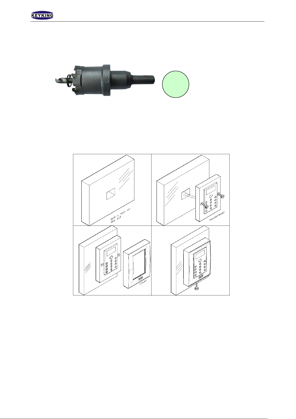
1. Drill a hole in the wall withф30mm
a). ф30mm drill tool b). Hole diameterф30mm
Note: This tool is used for metal and wooden wall, no good for stone or cement wall.
2. Wiring: Design the wiring between reader and controller, then process wiring.
3. Connection: Please refer to chapter 2 of the connections.
4. Fix reader:Use 2 ф4mm,30mm long screws to fix reader on the wall.
5. Cover up.
Page 27 of 29
Page 28

K E YK ING GR O UP LIMITED TA7003NT User Manual(V1.0)
Set short relay responding time in manage
Door open mode (Set to Card, not Card +
Wrong door open mode (To set door open
Chapter 5 FAQ
NO Descriptions Solution
1
2 Door stays opened
3 Password missing Reset password in PC.(Connect to PC fisrt)
4 Can not open door by flashing card
5
6
7 Door bell not working
No response for flashing(indicator off,buzzer
no beeping)
Set door open mode as “Card + PIN” in normal
state, but can not open th e doo r by card + PIN.
Can not open the door by PIN when it’s normal
state.
Power problem(check power supp ly )
Invalid card type(use suppor t ed card)
menu
Device not powered up(TA7003NT、lock)
Invalid card(register your card)
PIN)
Invalid card(register your card)
Wrong password (Check password or set a
new one)
Press # when finish entering password
Enter password 3 or 4 seconds later (must be
entered in 10 seconds)
Fail add PIN user(Retry)
Wrong password (enter the password again)
Forget to press “ * ” before entering PIN.
Forget to press ” # “ after entering PIN.
mode as PIN or Card + PIN)
No connected door bells
Cable problem
Faulty door bells
8 Wrong Time/Date Set Time/Date in manage menu.
Page 28 of 29
Page 29

K E YK ING GR O UP LIMITED TA7003NT User Manual(V1.0)
4
5
7
8 9
17
18
Attached:
Note:Please record card registration events as per attached form when using Card/Card + PIN mode. This
will help to make a good management if customer wants to register a card or delete a card.
Card User Records
NO Name Card Number PIN Register Date Note
1
2
3
6
10
11
12
13
14
15
16
19
…….
30000
Page 29 of 29
 Loading...