


Istruzioni ed avvertenze per l’installazione e l’uso
Instructions and warnings for installation and use
Instructions et avertissements pour l’installation et l’usage
Instrucciones y advertencias para su instalación y uso
Anleitungen und Hinweise zu Installation und Einsatz
Instruções e advertências para a instalação e utilização
TURBO 250
Motoriduttori per scorrevoli
Gear-motor for sliding gates
Motoreducteur pour coulissants
Motorreductores para rejas correderas
Getriebe für Schiebegitter
Motorredutores para portões de correr
Napęd silnikowy do bram przesuwnych
Management
System
ISO 9001:2008
www.tuv.com
ID 9105043769

IT
INDICE
1
Avvertenze per la sicurezza
pag. 3
2
2.1
2.2
Introduzione al prodotto
Descrizione del prodotto
Quadro d’insieme e caratteristiche tecniche
pag. 4
pag. 4
pag. 4
3
Veriche preliminari
pag. 5
4
4.1
4.2
4.3
4.4
4.5
Installazione del prodotto
Funzionamento manuale
Installazione
Fissaggio
Fissaggio cremagliera
Fissaggio necorsa
pag. 5
pag. 5
pag. 5
pag. 6
pag. 6
pag. 7
5
5.1
5.2
Collaudo e messa in servizio
Collaudo
Messa in servizio
pag. 7
pag. 7
pag. 7
6
Istruzioni ed avvertenze destinate
all’utilizzatore nale
pag. 8
7
Dichiarazione CE di conformità
pag. 59
2

1 - AVVERTENZE PER LA SICUREZZA
IT
ATTENZIONE – ISTRUZIONI ORIGINALI – importanti istruzioni
di sicurezza. É importante per la sicurezza delle persone se-
guire le seguenti istruzioni di sicurezza. Conservare queste
istruzioni.
Leggere attentamente le istruzioni prima di eseguire l’installazione.
La progettazione e la fabbricazione dei dispositivi che compongono il prodotto e le informazioni contenute nel presente
manuale rispettano le normative vigenti sulla sicurezza. Ciò
nonostante un’installazione e una programmazione errata possono causare gravi ferite alle persone che eseguono il lavoro
e a quelle che useranno l’impianto. Per questo motivo, durante
l’installazione, è importante seguire attentamente tutte le istruzioni riportate in questo manuale.
Non procedere con l’installazione se si hanno dubbi di qualunque
natura e richiedere eventuali chiarimenti al Servizio Assistenza Key
Automation.
Per la legislazione Europea la realizzazione di una porta auto-
matica o un cancello automatico deve rispettare le norme previste dalla Direttiva 2006/42/CE (Direttiva Macchine) e in particolare, le norme EN 12445; EN 12453; EN 12635 e EN 13241-1,
che consentono di dichiarare la conformità dell’automazione.
In considerazione di ciò, il collegamento denitivo dell’automatismo
alla rete elettrica, il collaudo dell’impianto, la sua messa in servizio
e la manutenzione periodica devono essere eseguiti da personale
qualicato ed esperto, rispettando le istruzioni riportate nel riquadro
“Collaudo e messa in servizio dell’automazione”.
Inoltre, egli dovrà farsi carico di stabilire anche le prove previste in
funzione dei rischi presenti e dovrà vericare il rispetto di quanto
previsto da leggi, normative e regolamenti: in particolare, il rispetto
di tutti i requisiti della norma EN 12445 che stabilisce i metodi di
prova per la verica degli automatismi per porte e cancelli.
ATTENZIONE - Prima di iniziare l’installazione, effettuare le seguenti analisi e veriche:
vericare che i singoli dispositivi destinati all’automazione siano
adatti all’impianto da realizzare. Al riguardo, controllare con particolare attenzione i dati riportati nel capitolo “Caratteristiche tecniche”.
Non effettuare l’installazione se anche uno solo di questi dispositivi
non è adatto all’uso;
vericare se i dispositivi acquistati sono sufcienti a garantire la sicurezza dell’impianto e la sua funzionalità;
eseguire l’analisi dei rischi che deve comprendere anche l’elenco
dei requisiti essenziali di sicurezza riportati nell’Allegato I della Direttiva Macchine, indicando le soluzioni adottate. L’analisi dei rischi
è uno dei documenti che costituiscono il fascicolo tecnico dell’automazione. Questo dev’essere compilato da un installatore professionista.
Considerando le situazioni di rischio che possono vericarsi
durante le fasi di installazione e di uso del prodotto è necessario installare l’automazione osservando le seguenti avvertenze:
comunque da una persona con qualica similare in modo da prevenire ogni rischio;
se sostanze liquide penetrano all’interno delle parti dei componenti
dell’automazione, scollegare immediatamente l’alimentazione elettrica e rivolgersi al Servizio Assistenza Key Automation. L’utilizzo
dell’automazione in tali condizioni può causare situazioni di pericolo;
non mettere i vari componenti dell’automazione vicino a fonti di ca-
lore né esporli a amme libere. Tali azioni possono danneggiarli ed
essere causa di malfunzionamenti, incendio o situazioni di pericolo;
tutte le operazioni che richiedono l’apertura del guscio di protezione dei vari componenti dell’automazione, devono avvenire con la
centrale scollegata dall’alimentazione elettrica. Se il dispositivo di
sconnessione non è a vista, apporre un cartello con la seguente
dicitura: “MANUTENZIONE IN CORSO”;
tutti i dispositivi devono essere collegati ad una linea di alimentazione elettrica dotata di messa a terra di sicurezza;
il prodotto non può essere considerato un efcace sistema di protezione contro l’intrusione. Se desiderate proteggervi efcacemente,
è necessario integrare l’automazione con altri dispositivi;
il prodotto può essere utilizzato esclusivamente dopo che è stata
effettuata la “messa in servizio” dell’automazione, come previsto nel
paragrafo “Collaudo e messa in servizio dell’automazione”;
prevedere nella rete di alimentazione dell’impianto un dispositivo di
disconnessione con una distanza di apertura dei contatti che consenta la disconnessione completa nelle condizioni dettate dalla categoria di sovratensione III;
per la connessione di tubi rigidi e essibili o passacavi utilizzare
raccordi conformi al grado di protezione IP55 o superiore;
l’impianto elettrico a monte dell’automazione deve rispondere alle
vigenti normative ed essere eseguito a regola d’arte;
si consiglia di utilizzare un pulsante di emergenza da installare nei
pressi dell’automazione (collegato all’ingresso STOP della scheda
di comando) in modo che sia possibile l’arresto immediato in caso
di pericolo;
questo dispositivo non è destinato a essere usato da persone (bambini compresi) le cui capacità siche, sensoriali o mentali siano ridotte, oppure con mancanza di esperienza o di conoscenza, a meno
che esse abbiano potuto beneciare, attraverso l’intermediazione di
una persona responsabile della loro sicurezza, di una sorveglianza
o di istruzioni riguardanti l’uso del dispositivo;
prima di avviare l’automazione assicurarsi che le persone non siano
nelle immediate vicinanze;
prima di procedere a qualsiasi operazione di pulizia e manutenzione
dell’automazione eseguire la disconnessione dalla rete elettrica;
particolare attenzione per evitare lo schiacciamento tra la parte gui-
data ed eventuali elementi ssi circostanti;
non eseguire modiche su nessuna parte dell’automatismo se non
quelle previste nel presente manuale. Operazioni di questo tipo
possono solo causare malfunzionamenti. Il costruttore declina ogni
responsabilità per danni derivanti da prodotti modicati arbitrariamente;
evitare che le parti dei componenti dell’automazione possano venire
immerse in acqua o in altre sostanze liquide. Durante l’installazione evitare che i liquidi possano penetrare all’interno dei dispositivi
presenti;
se il cavo di alimentazione risulta danneggiato esso deve essere
sostituito dal costruttore o dal suo servizio di assistenza tecnica o
i bambini devono essere sorvegliati per sincerarsi che non giochino
con l’apparecchio.
ATTENZIONE - Il materiale dell’imballaggio di tutti i componenti
dell’automazione deve essere smaltito nel pieno rispetto della
normativa presente a livello locale.
ATTENZIONE - I dati e le informazioni indicate in questo manuale sono da ritenersi suscettibili di modica in qualsiasi momento e senza obbligo di preavviso da parte di Key Automation
S.r.l.
3
IT
2 - INTRODUZIONE AL PRODOTTO
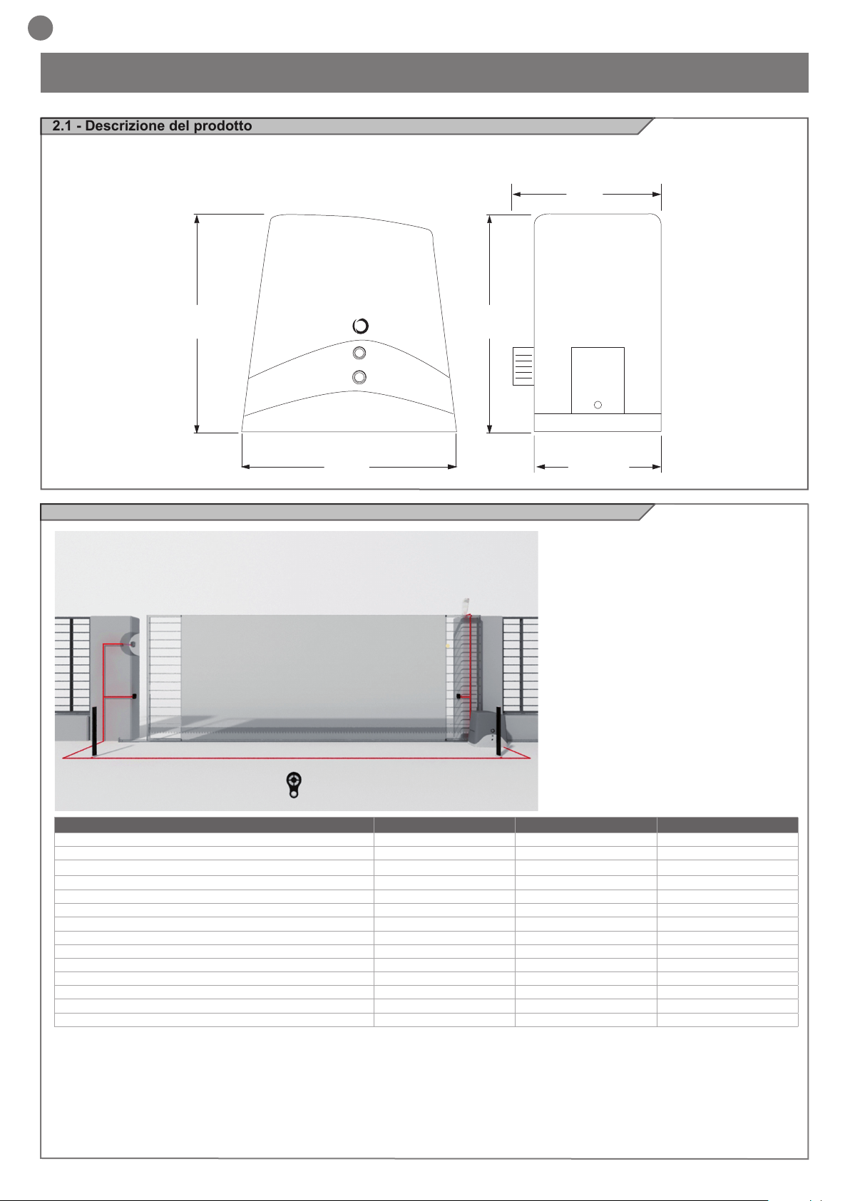
2.1 - Descrizione del prodotto
Motoriduttore elettromeccanico irreversibile per cancelli scorrevoli dal peso massimo di 2500 Kg con alimentazione a 230 Vac e 400 Vac.
270
390
360
390
230
2.2 - Quadro d’insieme e caratteristiche tecniche
4
5
3
6
DATI TECNICI SC202MHD SC252M
Velocità * cm/s 20 20
Coppia Nm 57 57
Ciclo di lavoro % 50/70* 30
Centrale di comando CT102B CT102B
Alimentazione Vac 230 230
Assorbimento motore A 4 4
Potenza assorbita W 580 580
Condensatore µF 25 35
Termoprotezione °C 150 150
Grado di protezione IP 44 44
Dimensioni (L-P-H) mm 360-270-390 360-270-390
Peso kg 25 24
Temperatura di esercizio °C -20+55 -20+55
Peso massimo cancello kg 2000 2500
* Valore variabile in relazione al peso del cancello
LIMITE D’IMPIEGO: i limiti d’impiego si riferiscono al peso raccomandato (circa 2/3 del peso massimo consentito). L’utilizzo con il peso massimo consentito potrebbe ridurre le prestazioni indicate nei dati tecnici. Il ciclo di lavoro, i tempi di utilizzo e il numero di cicli consecutivi hanno
valore indicativo. Sono rilevati statisticamente in condizioni medie di utilizzo e non possono essere certi per ogni singolo caso. Si riferiscono
al periodo nel quale il prodotto funziona senza necessità di manutenzione straordinaria. Ogni ingresso automatico presenta elementi variabili
quali: attriti, bilanciature e condizioni ambientali che possono modicare in maniera sostanziale sia la durata che la qualità di funzionamento
dell’ingresso automatico o di parte dei suoi componenti (fra i quali gli automatismi). É compito dell’installatore adottare coefcienti di sicurez-
za adeguati ad ogni particolare installazione.
3
INSTALLAZIONE STANDARD
2
11
1 Colonnina con fotocellula
2 Automazione motoriduttore
3 Fotocellula di rilevazione
4 Lampeggiante di segnalazione
5 Selettore a chiave
6 Trasmettitore radio
4
3 - VERIFICHE PRELIMINARI
IT
Prima di installare il prodotto vericare e controllare i seguenti punti:
la struttura del cancello deve essere solida ed appropriata;
durante la corsa, il cancello non deve presentare eccessivi sbandamenti laterali;
il sistema di ruote/rotaia inferiore e rulli/guida superiore deve funzionare senza eccessivi attriti
4 - INSTALLAZIONE DEL PRODOTTO
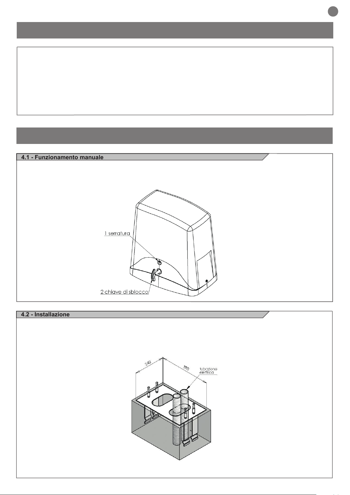
4.1 - Funzionamento manuale
Inserire la chiave in dotazione nella posizione 1 e ruotare di 90° in
senso antiorario (g.3).
per evitare il deragliamento del cancello devono essere installate le
battute di arresto dello scorrevole, sia in apertura che in chiusura, e
un secondo rullo/guida superiore nel pieno rispetto della normativa
vigente;
nei cancelli preesistenti eliminare l’eventuale serratura manuale;
portare alla base del cancello le canaline di adduzione dei cavi di
alimentazione (Ø25-50mm) e di collegamento esterno (fotocellula,
lampeggiante, selettore a chiave, ecc.).
Inserire la chiave di sblocco nella posizione 2 e ruotare in senso ora-
rio no al completo sblocco del pignone (g.3).
4.2 - Installazione
Prima di passare all’installazione si consiglia di effettuare le seguenti veriche oltre ad accertare che la struttura sia conforme alle norme vigenti.
Rispettare le misure di ingombro, creare un solido basamento in
Fig. 3
calcestruzzo e ssare a terra la piastra di base annegandola nel
calcestruzzo mediante le zanche e viti di ssaggio (g.4).Se il basa-
mento è già esistente utilizzare dei robusti tasselli ad espansione;
prevedere una o più tubazione per il passaggio dei cavi elettrici.
Fig. 4
N.B. e’ necessario conoscere le dimensioni della cremagliera per poter calcolare con precisione il posizionamento della contropiastra.
5
IT
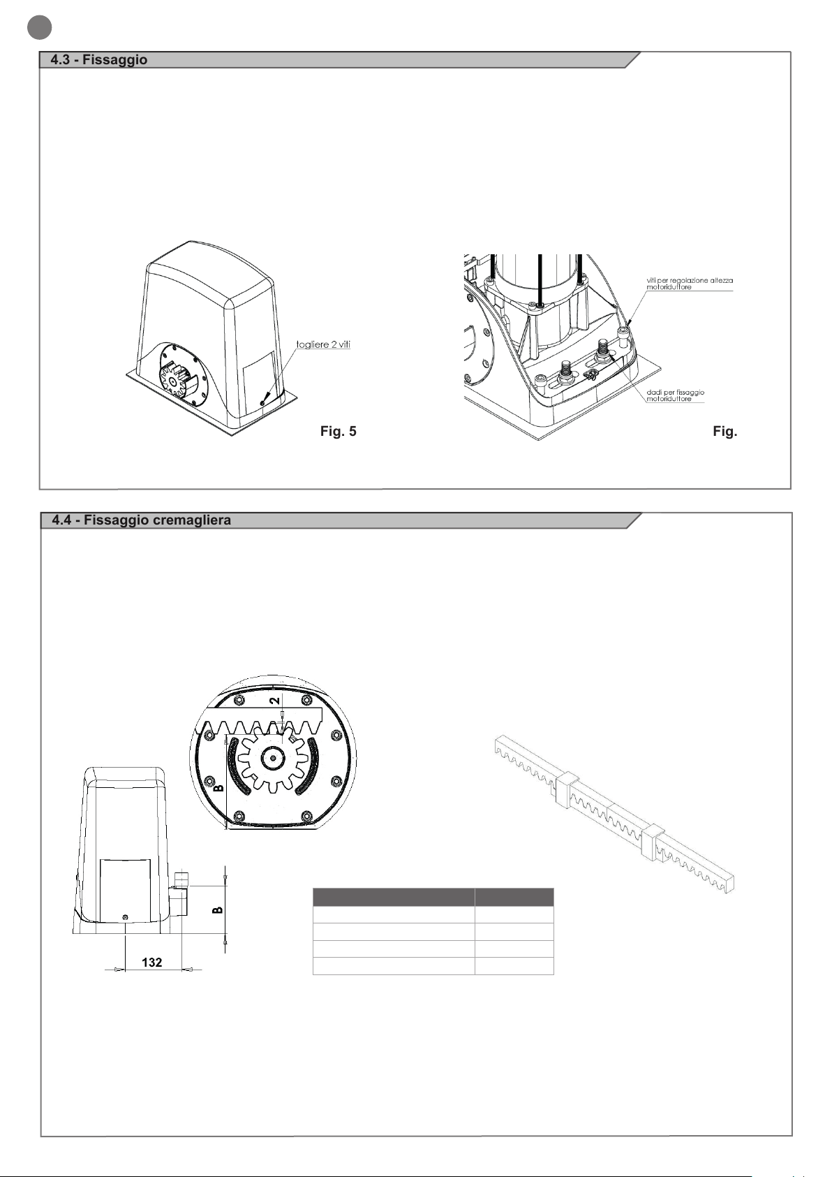
4.3 - Fissaggio
Aprire l’imballo e vericare che tutti gli elementi che compongono
l’automatismo siano integri.
Togliere il coperchio svitando le viti (g.5).
Appoggiare il motoriduttore sulla piastra.
Inserire le 4 rondelle + dadi autobloccanti per ssare il motore (g.6).
Qualora la regolazione consentita dalla cremagliera non fosse suf-
ciente è possibile compensare l’altezza del motoriduttore agendo
Fig. 5 Fig. 6
sulle 4 viti più esterne (g.6).
Terminata la regolazione ssare energicamente i 4 dadi autobloc-
canti, assicurarsi che durante tutta la corsa del cancello, il motoriduttore sia ben saldo a terra.
Si consiglia, dopo alcune manovre del motoriduttore, un ulteriore
ssaggio delle viti.
4.4 - Fissaggio cremagliera
Per una corretta installazione della cremagliera sbloccare il motoriduttore nel modo indicato nella (g.3) e portare il cancello in completa apertura.
Appoggiare un elemento di cremagliera al pignone e ssare lo stesso con viti e distanziali al cancello.
Spostare manualmente il cancello portando il pignone in corrispondenza dell’ultimo distanziale.
MODELLO B
SC202MHD 112 mm
SC252M 112 mm
SC202MHD + 480RM6Z12 115 mm
SC252M + 480RM6Z12 115 mm
Fig. 7
Fissare l’elemento di cremagliera denitivamente.
Per un corretto posizionamento degli altri elementi e garantire la
loro rettilineità è necessario utilizzare un elemento di cremagliera
usandolo come appoggio e riferimento (g.8).
Bisogna inoltre garantire un’aria fra cremagliera e pignone di circa 2
mm (misura indicativa), così da non far gravare il peso del cancello
sul pignone del motoriduttore (g.7).
Fig. 8
6

4.5 - Fissaggio necorsa
IT
Il cancello deve essere dotato di fermi di arresto in apertura e in
chiusura che impediscano il deragliamento del cancello stesso.
La posizione del fermo d’arresto deve garantire che le staffe di necorsa non entrino in collisione con il pignone .
Portare manualmente il cancello in apertura lasciando, a seconda
del peso del cancello, una luce da 30 a 50 mm tra il cancello stesso
e l’arresto meccanico.
Fissare la staffa del necorsa mediante i grani (g.10) lasciando
una luce tra il necorsa magnetico e il motoriduttore di 10 mm max
(g.9), ripetere l’operazione con il cancello in chiusura.
ATTENZIONE: i necorsa di apertura e chiusura devono intervenire minimo 20 mm dalla battuta meccanica (g.11).
Fig. 9
OPEN
Fig. 10
MIN 20
Fig. 11
7
IT
5 - COLLAUDO E MESSA IN SERVIZIO
Il collaudo dell impianto va eseguito da un tecnico qualicato che
deve effettuare le prove richieste dalla normativa di riferimento in
funzione dei rischi presenti, vericando il rispetto di quanto previsto
5.1 - Collaudo
Tutti i componenti dell’impianto devono essere collaudati seguendo
le procedure indicate nei rispettivi manuali di istruzioni;
controllare che siano rispettate le indicazioni del Capitolo 1 – Avvertenze per la sicurezza;
controllare che il cancello o la porta si possano muovere liberamente una volta sbloccata l’automazione e che siano in equilibrio e rimangano quindi fermi se lasciati in qualsiasi posizione;
5.2 - Messa in servizio
A seguito del positivo collaudo di tutti (e non solo di alcuni) i dispositivi dell’impianto si può procedere con la messa in servizio;
è necessario realizzare e conservare per 10 anni il fascicolo tecnico
dell’impianto che dovrà contenere lo schema elettrico, il disegno o
foto dell’impianto, l’analisi dei rischi e le soluzioni adottate, la dichiarazione di conformità del fabbricante di tutti i dispositivi collegati,
il manuale istruzioni di ogni dispositivo e il piano di manutenzione
dell’impianto;
dalle normative, in particolare la norma EN12445 che indica i metodi di prova per gli automatismi per porte e cancelli.
controllare il corretto funzionamento di tutti i dispositivi collegati (fotocellule, bordi sensibili, pulsanti di emergenza, altro) effettuando
delle prove di apertura, chiusura e arresto del cancello o della porta
tramite i dispositivi di comando collegati (trasmettitori, pulsanti, selettori);
effettuare le misurazioni della forza d’impatto come previsto dalla
normativa EN12445 regolando le funzioni di velocità, forza motore e
rallentamenti della centrale nel caso in cui le misurazioni non diano i
risultati desiderati no a trovare il giusto settaggio.
realizzare e consegnare all’utilizzatore nale la dichiarazione di
conformità , le istruzioni e avvertenze d’uso per l’utilizzatore nale e
il piano di manutenzione dell’impianto;
accertarsi che l’utilizzatore abbia compreso il corretto funzionamento automatico, manuale e di emergenza dell’automazione;
informare anche in forma scritta l’utilizzatore nale sui pericoli e rischi ancora presenti;
ssare sul cancello o la porta una targa indicante i dati dell’automazione, il nome del responsabile della messa in servizio, il numero di
matricola e l’anno di costruzione, il marchio CE;
ssare una targa che indichi le operazioni necessarie per sbloccare
manualmente l’impianto;
ATTENZIONE - dopo la rilevazione di un ostacolo, il cancello o la
porta si ferma in apertura e viene esclusa la chiusura automatica;
per riprendere il movimento bisogna premere il pulsante di comando o usare il trasmettitore.
8

6 - ISTRUZIONI ED AVVERTENZE DESTINATE ALL’UTILIZZATORE FINALE
Key Automation S.r.l. produce sistemi per l’automazione di cancelli,
porte garage, porte automatiche, serrande, barriere per parcheggi e stradali. Key Automation non è però il produttore della vostra
automazione, che è invece il risultato di un’opera di analisi, valutazione, scelta dei materiali, e realizzazione dell’impianto eseguita
dal vostro installatore di ducia. Ogni automazione è unica e solo il
vostro installatore possiede l’esperienza e la professionalità necessarie ad eseguire un impianto secondo le vostre esigenze, sicuro ed
afdabile nel tempo, e soprattutto a regola d’arte, rispondente cioè
alle normative in vigore. Anche se l’automazione in vostro possesso
soddisfa il livello di sicurezza richiesto dalle normative, questo non
esclude l’esistenza di un “rischio residuo”, cioè la possibilità che si
possano generare situazioni di pericolo, solitamente dovute ad un
utilizzo incosciente o addirittura errato, per questo motivo desideriamo darvi alcuni consigli sui comportamenti da seguire :
• Prima di usare per la prima volta l’automazione, fatevi spiegare
dall’installatore l’origine dei rischi residui.
• Conservate il manuale per ogni dubbio futuro e consegnatelo ad
un eventuale nuovo proprietario dell’automazione.
• Un uso incosciente ed improprio dell’automazione può farla diventare pericolosa: non comandate il movimento dell’automazione se
nel suo raggio di azione si trovano persone, animali o cose.
• Bambini: Se adeguatamente progettato un impianto di automazione garantisce un alto grado di sicurezza, impedendo con i suoi
sistemi di rilevazione il movimento in presenza di persone o cose,
e garantendo un’attivazione sempre prevedibile e sicura. È comunque prudente vietare ai bambini di giocare in prossimità dell’automazione e per evitare attivazioni involontarie non lasciare i telecomandi alla loro portata.
• Anomalie: Non appena notate qualunque comportamento anomalo da parte dell’automazione, togliete alimentazione elettrica all’impianto ed eseguite lo sblocco manuale. Non tentate da soli alcuna
riparazione, ma richiedete l’intervento del vostro installatore di ducia: nel frattempo l’impianto può funzionare come un’apertura non
automatizzata, una volta sbloccato il motoriduttore con apposita
chiave di sblocco data in dotazione con l’impianto.
• In caso di rotture o assenza di alimentazione: Attendendo l’intervento del vostro installatore, o il ritorno dell’energia elettrica se l’impianto non è dotato di batterie tampone, l’automazione può essere
azionata come una qualunque apertura non automatizzata. Per fare
ciò è necessario eseguire lo sblocco manuale.
• Sblocco e movimento manuale: prima di eseguire questa operazione porre attenzione che lo sblocco può avvenire solo quando
l’anta è ferma.
• Manutenzione: Come ogni macchinario la vostra automazione
ha bisogno di una manutenzione periodica afnché possa funzio-
nare più a lungo possibile ed in completa sicurezza. Concordate
con il vostro installatore un piano di manutenzione con frequenza
periodica; Key Automation consiglia un intervento ogni 6 mesi per
un normale utilizzo domestico, ma questo periodo può variare in
funzione dell’intensità d’uso. Qualunque intervento di controllo, manutenzione o riparazione deve essere eseguito solo da personale
qualicato.
• Non modicate l’impianto ed i parametri di programmazione e di
regolazione dell’automazione: la responsabilità è del vostro installatore.
• Il collaudo, le manutenzioni periodiche e le eventuali riparazioni
devono essere documentate da chi le esegue e i documenti conservati dal proprietario dell’impianto.
Gli unici interventi che vi sono possibili e vi consigliamo di effettuare periodicamente sono la pulizia dei vetrini delle fotocellule e la
rimozione di eventuali foglie o sassi che potrebbero ostacolare l’automatismo. Per impedire che qualcuno possa azionare il cancello o
la porta, prima di procedere, ricordatevi di sbloccare l’automatismo
e di utilizzare per la pulizia solamente un panno leggermente inumidito con acqua.
• Smaltimento: Al termine della vita dell’automazione, assicuratevi
che lo smaltimento sia eseguito da personale qualicato e che i
materiali vengano riciclati o smaltiti secondo le norme valide a livello
locale.
• Azionare il comando del cancello o della porta (con telecomando,
con selettore a chiave, ecc.); se tutto è a posto il cancello o la porta
si aprirà o chiuderà normalmente, altrimenti il lampeggiante farà alcuni lampeggi e la manovra non partirà.
Con le sicurezze fuori uso è necessario far riparare quanto prima
l’automatismo.
Sostituzione pila del telecomando: se il vostro trasmettitore dopo
qualche tempo vi sembra funzionare peggio, oppure non funzionare
affatto, potrebbe semplicemente dipendere dall’esaurimento della
pila (a seconda dell’uso, possono trascorrere da diversi mesi no ad
oltre un anno). Ve ne potete accorgere dal fatto che la spia di conferma della trasmissione non si accende, oppure si accende solo
per un breve istante.
Le pile contengono sostanze inquinanti: non gettarle nei riuti comuni ma utilizzare i metodi previsti dai regolamenti locali.
Vi ringraziamo per aver scelto keyautomation e vi invitiamo a visitare il nostro sito internet www.keyautomation.it per ulteriori informazioni.
9

EN
INDEX
1
Safety warnings
pag. 11
2
2.1
2.2
Product overview
Product description
Set panel and technical characteristics
pag. 12
pag. 12
pag. 12
3
Preliminary checks
pag. 13
4
4.1
4.2
4.3
4.4
4.5
Installing the product
Manual running
Installing
Fixing
Rack assembling
Limit switch xing
pag. 13
pag. 13
pag. 13
pag. 14
pag. 14
pag. 15
5
5.1
5.2
Testing and commissioning
Testing
Commissioning
pag. 15
pag. 15
pag. 15
6
Instructions and warnings for the
end user
pag. 16
7
EC Declaration of Conformity
pag. 59
10

1 - SAFETY WARNINGS
CAUTION – ORIGINAL INSTRUCTIONS - important safety instructions. Compliance with the safety instructions below is
important for personal safety. Save these instructions.
Read the instructions carefully before proceeding with installation.
The design and manufacture of the devices making up the
product and the information in this manual are compliant with
current safety standards. However, incorrect installation or
programming may cause serious injury to those working on or
using the system. Compliance with the instructions provided
here when installing the product is therefore extremely impor-
tant.
If in any doubt regarding installation, do not proceed and contact the
Key Automation Technical Service for clarications.
Under European legislation, an automatic door or gate system
must comply with the standards envisaged in the Directive
2006/42/EC (Machinery Directive) and in particular standards
EN 12445; EN 12453; EN 12635 and EN 13241-1, which enable
declaration of presumed conformity of the automation system.
Therefore, nal connection of the automation system to the electrical mains, system testing, commissioning and routine maintenance
must be performed by skilled, qualied personnel, in observance of
the instructions in the “Testing and commissioning the automation
system” section.
The aforesaid personnel are also responsible for the tests required
to verify the solutions adopted according to the risks present, and
for ensuring observance of all legal provisions, standards and regulations, with particular reference to all requirements of the EN 12445
standard which establishes the test methods for testing door and
gate automation systems.
WARNING - Before starting installation, perform the following
checks and assessments:
ensure that every device used to set up the automation system is
suited to the intended system overall. For this purpose, pay special
attention to the data provided in the “Technical specications” section. Do not proceed with installation if any one of these devices is
not suitable for its intended purpose;
EN
do not allow parts of the automation system to be immersed in water
or other liquids. During installation ensure that no liquids are able to
enter the various devices;
should this occur, disconnect the power supply immediately and
contact a Key Automation Service Centre. Use of the automation
system in these conditions may cause hazards;
never place automation system components near to sources of heat
or expose them to naked lights. This may damage system components and cause malfunctions, re or hazards;
all operations requiring opening of the protective housings of various automation system components must be performed with the
control unit disconnected from the power supply. If the disconnect
device is not in a visible location, afx a notice stating: “MAINTENANCE IN PROGRESS”:
connect all devices to an electric power line equipped with an
earthing system;
the product cannot be considered to provide effective protection
against intrusion. If effective protection is required, the automation
system must be combined with other devices;
the product may not be used until the automation system “commissioning” procedure has been performed as specied in the “Automation system testing and commissioning” section;
the system power supply line must include a circuit breaker device
with a contact gap allowing complete disconnection in the condi-
tions specied by class III overvoltage;
use unions with IP55 or higher protection when connecting hoses,
pipes or cable glands;
the electrical system upstream of the automation system must comply with the relevant regulations and be constructed to good workmanship standards;
users are advised to install an emergency stop button close to the
automation system (connected to the control PCB STOP input) to
allow the door to be stopped immediately in case of danger;
check that the devices purchased are sufcient to guarantee system
safety and functionality;
perform a risk assessment, including a list of the essential safety
requirements as envisaged in Annex I of the Machinery Directive,
specifying the solutions adopted. The risk assessment is one of the
documents included in the automation system’s technical le. This
must be compiled by a professional installer.
Considering the risk situations that may arise during installation phases and use of the product, the automation system
must be installed in compliance with the following safety precautions:
never make modications to any part of the automation system
other than those specied in this manual. Operations of this type
can only lead to malfunctions. The manufacturer declines all liability
for damage caused by unauthorised modications to products;
if the power cable is damaged, it must be replaced by the manufacturer or its after-sales service, or in all cases by a person with similar
qualications, to prevent all risks;
this device is not intended for use by persons (including children)
with impaired physical, sensory or mental capacities, or with lack
of experience or skill, unless a person responsible for their safety
provides surveillance or instruction in use of the device;
before starting the automation system, ensure that there is no-one
in the immediate vicinity;
before proceeding with any cleaning or maintenance work on the
automation system, disconnect it from the electrical mains;
special care must be taken to avoid crushing between the part ope-
rated by the automation system and any xed parts around it;
children must be supervised to ensure that they do not play with the
equipment.
WARNING - The automation system component packaging material must be disposed of in full observance of current local
waste disposal legislation.
WARNING - The data and information in this manual are subject
to modication at any time, with no obligation on the part of
Key Automation S.r.l. to provide notice.
11

EN
2 - INTRODUCING THE PRODUCT
2.1 - Product description
Irreversibile electromechanical gearmotor for sliding gates weighing up to 2500 kg at 230 Vac / 400 Vac.
270
390
360
2.2 - Set panel and and technical characteristics
5
3
6
390
230
4
3
STANDARD INSTALLATION
2
11
1 Post for photocells
2 Automation electromechanical
3 Photocell detectors
4 Flashing light
5 Key switch
6 Radio transmitter
TECHNICAL DATA SC202MHD SC252M
Speed* cm/s 20 20
Torque Nm 57 57
Working cycle % 50/70* 30
Control unit CT102B CT102B
Power Vac 230 230
Motor consumption A 4 4
Absorbed power W 580 580
Capacitor µF 25 35
Thermoprotection °C 150 150
Protection degree IP 44 44
Dimensions (L-P-H) mm 360-270-390 360-270-390
Weight kg 25 24
Working temperature °C -20+55 -20+55
Max gate weight kg 2000 2500
* Variable data according to gate weight
LIMIT USE: The limit use refer to the recommended weight (about 2/3 of maximum allowed weight). Use with maximum allowed weight
could reduce the above performance specications in tecnhical data. The working cycle, operating times and number of consecutive cycles
are merely approximate. These have been statistically determined in average conditions of use and are not certain for each single case.
They refer to the period when the product operates without the need for special maintenance.- Each automatic entrance features variable
factors such as: friction, balancing and environmental conditions that can substantially change both the duration and operating quality of the
automatic entrance or part of its components (including automatic system). It is up to the installer to adopt adequate safety coefcients for
each single installation.
12
3 - PRELIMINARY CHECKS
1 lock
2 unlock keys
Electrical
pipeline
EN
Before the installation starts, we suggest to carry out following
inspections and operations:
the gate framework must be strong and suitable;
the gate must not show too many sideways slide skids during the
running;
the system of wheels/lower rail and roller/upper runner must work
without too many frictions;
4 - INSTALLING THE PRODUCT
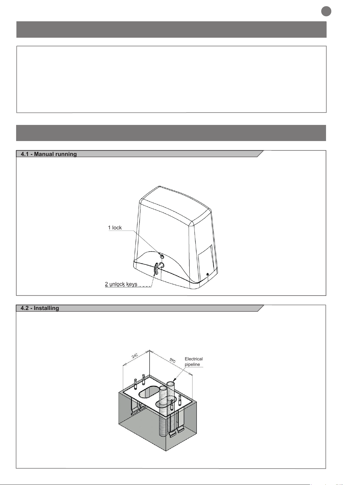
4.1 - Manual running
Insert the key in position 1 lock and rotate 90° counter-clockwise (g.3).
to avoid the gate derailment you must install the stop beats of the
sliding, whether at the opening or closing, and a second upper
roller/runner in full observance of the current law;
remove any manual lock in the beforehand gates;
take on the gate bottom the feed raceway of the feeding cables
(Ø25-50mm) and of external connection (photocell, ash-light, key
selector, etc...).
Insert the unlock key in position 2 and rotate clockwise until complete
unlock of the pinion (g.3).
4.2 - Installing
Before starting installation, you should carry out the following
checks, as well as making sure the structure is compliant with
current standards.
Follow the dimensions, create a solid concrete footing and x the
Fig. 3
base plate to the ground immerging it into the concrete using the
bracket clamps and xing screws (g.4). If the base already exists
use robust expanding wedges:
provide one or more pipelines for the laying of electrical cables.
Fig. 4
N.B. The exact dimensions of the rack must be known to allow precise calculation of the counterplate position.
13

EN
Remove 2 screws
Screws for the height
adjustment of the
reductioon gear
reduction gear
4.3 - Fixing
Open the packaging and check the condition of all the parts of the
automation.
Remove the lid unscrewing the screws see (g.5).
Place the reduction gear on the plate.
Insert the 4 washers + locknuts to x the gear (g.6).
If the allowed adjustment of the ratchet is not sufcient it is possible
to compensate the height of the reduction gear working on the 4
Fig. 5 Fig. 6
more external screws (g.6).
Once the adjustment is nished rmly x the 4 locknuts, making
sure that during the entire run of the gate, the reduction gear is
rmly to the ground.
The screws should be tightened again after the motor has been
operated a few times.
4.4 - Rack assembling
For the correct installation of the ratchet unlock the reduction gear
as shown in (g.3) and bring the gate to complete aperture.
Lay one element of the ratchet on the pinion and x the latter with
screws and tingles to the gate.
Manually move the gate bringing the pinion in correspondance with
the last tingle.
Denitively x the element of the ratchet.
MODEL B
SC202MHD 112 mm
SC252M 112 mm
SC202MHD + 480RM6Z12 115 mm
Fig. 7
SC252M + 480RM6Z12 115 mm
For the correct positioning of the other elements and to ensure
they are straight it is necessary to use a ratchet element using it as
reference and support.
Moreover it is necessary to ensure some air between the ratchet and
the pinion of about 2 mm (indicative measure), so that the weight of
the gate does not bear upon the pinion of the reduction gear.
Fig. 8
14
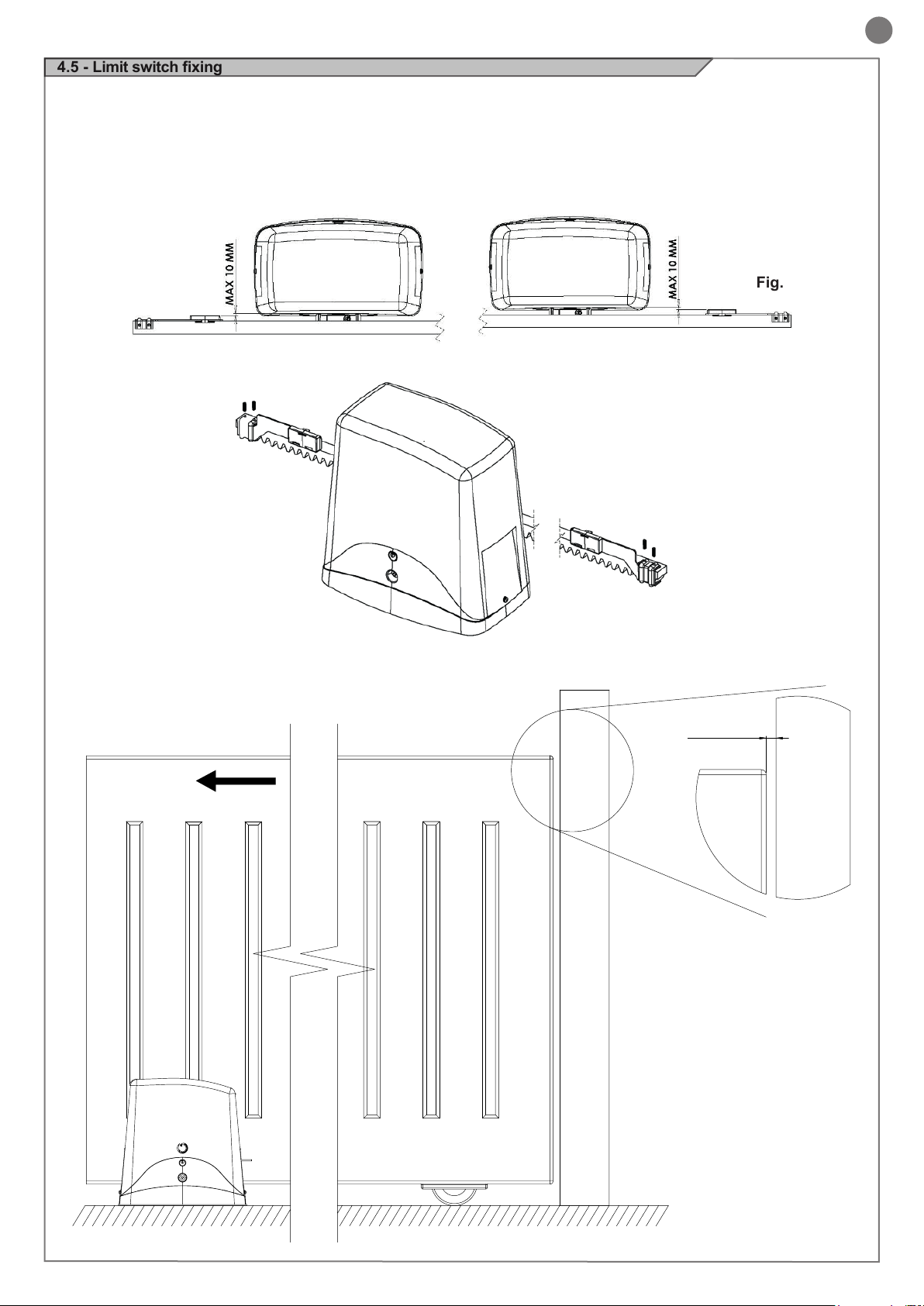
4.5 - Limit switch xing
EN
The gate must feature check stops for aperture and closure that
prevent the gate from derailing.
The position of the limit device must ensure that the limit devices do
not collide with the pinion.
Manually open the gate leaving, based on the weight of the gate, a
space between 30 a 50 mm. between the gate and the mechanical
stop.
Fix the limit device using the pins (g.10) leaving a space between
the magnetic limit device and the reduction gear of max 10 mm
(g.9) repeat the operation with the gate closed.
CAUTION: the opening and closing limit switches must intervene at least 20 mm from the mechanical end stop (g. 11)
Fig. 9
Fig. 10
OPEN
MIN 20
Fig. 11
15
EN
5 - TESTING AND COMMISSIONING THE AUTOMATION SYSTEM
The system must be tested by a qualied technician, who must
perform the tests required by the relevant standards in relation
to the risks present, to check that the installation complies with
5.1 - Testing
All system components must be tested following the procedures
described in their respective operator’s manuals;
ensure that the recommendations in Chapter 1 - Safety Warnings have been complied with;
check that the gate or door is able to move freely once the automation
system has been released and is well balanced, meaning that it will
remain stationery when released in any position;
5.2 - Commissioning
Once all (and not just some) of the system devices have passed the
testing procedure, the system can be commissioned;
the system’s technical dossier must be produced and kept for
10 years. It must contain the electrical wiring diagram, a drawing
or photograph of the system, the analysis of the risks and the
solutions adopted to deal with them, the manufacturer’s declaration of
conformity for all connected devices, the operator’s manual for
every device and the system maintenance plan;
x a dataplate with the details of the automation, the name of
the person who commissioned it, the serial number and year of
construction and the CE marking on the gate or door;
also t a sign specifying the procedure for releasing the system by
hand;
the relevant regulatory requirements, especially the EN12445
standard which species the test methods for gate and door automation
systems.
check that all connected devices (photocells, sensitive edges,
emergency buttons, etc.) are operating correctly by performing gate
or door opening, closing and stop tests using the connected control
devices (transmitters, buttons or switches);
perform the impact measurements as required by the EN12445
standard, adjusting the control unit’s speed, motor force and
deceleration functions if the measurements do not give the required
results, until the correct setting is obtained.
draw up the declaration of conformity, the instructions and
precautions for use for the end user and the system maintenance
plan and consign them to the end user;
ensure that the user has fully understood how to operate the system
in automatic, manual and emergency modes;
the end user must also be informed in writing about any risks and
hazards still present;
WARNING - after detecting an obstacle, the gate or door stops
during its opening travel and automatic closure is disabled; to
restart operation, the user must press the control button or use the
transmitter.
16

6 - INSTRUCTIONS AND WARNINGS FOR THE END USER
EN
Key Automation S.r.l. produces systems for the automation of gates,
garage doors, automatic doors, roller blinds and car-park and road
barriers. However, Key Automation is not the manufacturer of your
complete automation system, which is the outcome of the analysis,
assessment, choice of materials and installation work of your chosen installer. Every automation system is unique, and only your
installer has the experience and skill required to produce a safe,
reliable, durable system tailored to your needs, and above all that
complies with the relevant regulatory standards. Although your automation system complies with the regulation safety level, this does
not rule out the presence of “residual risk”, meaning the possibility
that hazards may occur, usually due to reckless or even incorrect
use. We would therefore like to give you some advice for the correct
use of the system:
• before using the automation system for the rst time, have the
installer explain the potential causes of residual risks to you;
• keep the manual for future reference, and pass it on to any new
owner of the automation system;
• reckless use and misuse of the automation system may make it
dangerous: do not operate the automation system with people, animal or objects within its range of action;
• a properly designed automation system has a high level of safety,
since its sensor systems prevent it from moving with people or obstacles present so that its operation is always predictable and safe.
However, as a precaution children should not be allowed to play close to the automation system, and to prevent involuntary activation,
remote controls must not be left within their reach;
• as soon as any system malfunction is noticed, disconnect the
electricity supply and perform the manual release procedure. Never
attempt repairs on your own; call in your installation engineer. In
the meantime the door or gate can be operated without automation
once the geared motor has been released using the release key
supplied with the system. In the event of safety devices out of service arrange for repairs to the automation immediately;
• Maintenance: Like any machine, your automation system needs
regular periodic maintenance to ensure its long life and total safety. Arrange a periodic maintenance schedule with your installation
engineer. Key Automation recommends that maintenance checks
should be carried out every six months for normal domestic use, but
this interval may vary depending on the level of use. Any inspection,
maintenance or repair work must only be carried out by qualied
staff.
• Never modify the automation system or its programming and setup
parameters: this is the responsibility of your installation engineer.
• Testing, routine maintenance and any repairs must be recorded by
the person who performs them and the documents must be conserved by the system’s owner.
The only procedures you are capable of, and which you are recommended to perform, are cleaning of the photocell glass and removal
of any leaves or stones that may obstruct the automation system.
To prevent anyone from activating the gate or door, release the automation system before starting. Clean only with a cloth dipped in
a little water.
At the end of its useful life, the automation system must be disman-
tled by qualied personnel, and the materials must be recycled or
disposed of in compliance with the legislation locally in force.
If after some time your remote control seems to have become less
effective, or stops operating completely, the battery may be at (depending on the level of use, this may take from several months up
to more than a year). You will realise this because the transmission
conrmation light does not come on, or only lights up for a very
short time.
Batteries contain pollutants: do not dispose of them with normal waste but follow the methods specied by the local regulations.
Thank you for choosing Key Automation S.r.l.; please visit our Inter-
net site www.keyautomation.it for further information.
• in the event of malfunctions or power failures: while waiting for the
engineer to come (or for the power to be restored if your system is
not equipped with buffer batteries), the door or gate can be used just
like any non-automated installation. To do this, the manual release
procedure must be carried out;
• manual release and operation: rst bear in mind that the release
procedure can only be carried out with the door or gate stationery.
17

FR
TABLE DES MATIÈRES
1
Consignes de sécurité
page 19
2
2.1
2.2
Présentation du produit
Description du produit
Tableau d’ensemble et caractéristiques
techniques
page 20
page 20
page 20
3
Vérications préalables
page 21
4
4.1
4.2
4.3
4.4
4.5
Installation du produit
Fonctionnement manuel
Installation
Fixation
Pose de la crémaillère
Fixation des dispositifs de n de course
page 21
page 21
page 21
page 22
page 22
page 23
5
5.1
5.2
Réception et mise en service
Réception
Mise en service
page 23
page 23
page 23
6
Instructions et avertissements
destinés à l’utilisateur nal
page 24
7
Déclaration CE de conformité
page 59
18
 Loading...