

Page 1

Istruzioni ed avvertenze per l’installazione e l’uso
Instructions and warnings for installation and use
Anleitungen und Hinweise zu Installation und Einsatz
Instrucciones y advertencias para su instalación y uso
Instructions et avertissements pour l’installation et l’usage
Instruções e advertências para a instalação e utilização
UP DOWN
MENU
SS
CT202
Centrale per due motori 230 Vac (120 Vac), per cancelli a battente
Control unit for two 230 Vac (120 Vac) motors, for swing gates
Logique de commande pour deux moteurs 230 Vca (120 Vca), pour portails battants
Central para dos motores de 230 Vca (120 Vca) para puertas de batiente
Steuergerät für zwei Drehtor-Motoren 230 Vac (120 Vac)
Unidade para dois motores 230 Vac (120 Vac), para portões de batente
Centrala dla dwóch silników 230 Vac (120 Vac), do bram skrzydłowych
Management
System
ISO 9001:2008
www.tuv.com
ID 9105043769
Page 2

IT
INDICE
1
Avvertenze per la sicurezza
pag. 3
2
2.1
2.2
2.3
2.4
Introduzione al prodotto
Descrizione della centrale
Descrizione dei collegamenti
Modelli e caratteristiche tecniche
Elenco cavi necessari
pag. 4
pag. 4
pag. 4
pag. 4
pag. 5
3
Veriche preliminari
pag. 5
4
4.1
4.2
4.3
4.4
4.5
Installazione del prodotto
Collegamenti elettrici
Visualizzazione modalità normale
Autoapprendimento della corsa
Personalizzazione dell’impianto - MENU BASE
Innesto ricevente radio
pag. 6
pag. 6
pag. 7
pag. 8
pag.10
pag.10
5
5.1
5.2
Collaudo e messa in servizio
Collaudo
Messa in servizio
pag. 11
pag. 11
pag. 11
6
Approfondimenti - MENU AVANZATO
pag. 12
7
Istruzioni ed avvertenze destinate
all’utilizzatore nale
pag. 13
8
Dichiarazione CE di conformità
pag. 87
2
Page 3

1 - AVVERTENZE PER LA SICUREZZA
IT
ATTENZIONE – ISTRUZIONI ORIGINALI – importanti istruzioni
di sicurezza. É importante per la sicurezza delle persone se-
guire le seguenti istruzioni di sicurezza. Conservare queste
istruzioni.
Leggere attentamente le istruzioni prima di eseguire l’installazione.
La progettazione e la fabbricazione dei dispositivi che compongono il prodotto e le informazioni contenute nel presente
manuale rispettano le normative vigenti sulla sicurezza. Ciò
nonostante un’installazione e una programmazione errata possono causare gravi ferite alle persone che eseguono il lavoro
e a quelle che useranno l’impianto. Per questo motivo, durante
l’installazione, è importante seguire attentamente tutte le istruzioni riportate in questo manuale.
Non procedere con l’installazione se si hanno dubbi di qualunque
natura e richiedere eventuali chiarimenti al Servizio Assistenza Key
Automation.
Per la legislazione Europea la realizzazione di una porta automatica o un cancello automatico deve rispettare le norme previste dalla Direttiva 2006/42/CE (Direttiva Macchine) e in particolare, le norme EN 12445; EN 12453; EN 12635 e EN 13241-1,
che consentono di dichiarare la conformità dell’automazione.
In considerazione di ciò, il collegamento denitivo dell’automatismo
alla rete elettrica, il collaudo dell’impianto, la sua messa in servizio
e la manutenzione periodica devono essere eseguiti da personale
qualicato ed esperto, rispettando le istruzioni riportate nel riquadro
“Collaudo e messa in servizio dell’automazione”.
Inoltre, egli dovrà farsi carico di stabilire anche le prove previste in
funzione dei rischi presenti e dovrà vericare il rispetto di quanto
previsto da leggi, normative e regolamenti: in particolare, il rispetto
di tutti i requisiti della norma EN 12445 che stabilisce i metodi di
prova per la verica degli automatismi per porte e cancelli.
ATTENZIONE - Prima di iniziare l’installazione, effettuare le seguenti analisi e veriche:
vericare che i singoli dispositivi destinati all’automazione siano
adatti all’impianto da realizzare. Al riguardo, controllare con particolare attenzione i dati riportati nel capitolo “Caratteristiche tecniche”.
Non effettuare l’installazione se anche uno solo di questi dispositivi
non è adatto all’uso;
vericare se i dispositivi acquistati sono sufcienti a garantire la sicurezza dell’impianto e la sua funzionalità;
eseguire l’analisi dei rischi che deve comprendere anche l’elenco
dei requisiti essenziali di sicurezza riportati nell’Allegato I della Direttiva Macchine, indicando le soluzioni adottate. L’analisi dei rischi
è uno dei documenti che costituiscono il fascicolo tecnico dell’automazione. Questo dev’essere compilato da un installatore professionista.
Considerando le situazioni di rischio che possono vericarsi
durante le fasi di installazione e di uso del prodotto è necessario installare l’automazione osservando le seguenti avvertenze:
comunque da una persona con qualica similare in modo da prevenire ogni rischio;
se sostanze liquide penetrano all’interno delle parti dei componenti
dell’automazione, scollegare immediatamente l’alimentazione elettrica e rivolgersi al Servizio Assistenza Key Automation. L’utilizzo
dell’automazione in tali condizioni può causare situazioni di pericolo;
non mettere i vari componenti dell’automazione vicino a fonti di ca-
lore né esporli a amme libere. Tali azioni possono danneggiarli ed
essere causa di malfunzionamenti, incendio o situazioni di pericolo;
tutte le operazioni che richiedono l’apertura del guscio di protezione dei vari componenti dell’automazione, devono avvenire con la
centrale scollegata dall’alimentazione elettrica. Se il dispositivo di
sconnessione non è a vista, apporre un cartello con la seguente
dicitura: “MANUTENZIONE IN CORSO”;
tutti i dispositivi devono essere collegati ad una linea di alimentazione elettrica dotata di messa a terra di sicurezza;
il prodotto non può essere considerato un efcace sistema di protezione contro l’intrusione. Se desiderate proteggervi efcacemente,
è necessario integrare l’automazione con altri dispositivi;
il prodotto può essere utilizzato esclusivamente dopo che è stata
effettuata la “messa in servizio” dell’automazione, come previsto nel
paragrafo “Collaudo e messa in servizio dell’automazione”;
prevedere nella rete di alimentazione dell’impianto un dispositivo di
disconnessione con una distanza di apertura dei contatti che consenta la disconnessione completa nelle condizioni dettate dalla categoria di sovratensione III;
per la connessione di tubi rigidi e essibili o passacavi utilizzare
raccordi conformi al grado di protezione IP55 o superiore;
l’impianto elettrico a monte dell’automazione deve rispondere alle
vigenti normative ed essere eseguito a regola d’arte;
si consiglia di utilizzare un pulsante di emergenza da installare nei
pressi dell’automazione (collegato all’ingresso STOP della scheda
di comando) in modo che sia possibile l’arresto immediato in caso
di pericolo;
questo dispositivo non è destinato a essere usato da persone (bambini compresi) le cui capacità siche, sensoriali o mentali siano ridotte, oppure con mancanza di esperienza o di conoscenza, a meno
che esse abbiano potuto beneciare, attraverso l’intermediazione di
una persona responsabile della loro sicurezza, di una sorveglianza
o di istruzioni riguardanti l’uso del dispositivo;
prima di avviare l’automazione assicurarsi che le persone non siano
nelle immediate vicinanze;
prima di procedere a qualsiasi operazione di pulizia e manutenzione
dell’automazione eseguire la disconnessione dalla rete elettrica;
particolare attenzione per evitare lo schiacciamento tra la parte gui-
data ed eventuali elementi ssi circostanti;
non eseguire modiche su nessuna parte dell’automatismo se non
quelle previste nel presente manuale. Operazioni di questo tipo
possono solo causare malfunzionamenti. Il costruttore declina ogni
responsabilità per danni derivanti da prodotti modicati arbitrariamente;
evitare che le parti dei componenti dell’automazione possano venire
immerse in acqua o in altre sostanze liquide. Durante l’installazione evitare che i liquidi possano penetrare all’interno dei dispositivi
presenti;
se il cavo di alimentazione risulta danneggiato esso deve essere
sostituito dal costruttore o dal suo servizio di assistenza tecnica o
i bambini devono essere sorvegliati per sincerarsi che non giochino
con l’apparecchio.
ATTENZIONE - Il materiale dell’imballaggio di tutti i componenti
dell’automazione deve essere smaltito nel pieno rispetto della
normativa presente a livello locale.
ATTENZIONE - I dati e le informazioni indicate in questo manuale sono da ritenersi suscettibili di modica in qualsiasi momento e senza obbligo di preavviso da parte di Key Automation
S.r.l.
3
Page 4
IT
2 - INTRODUZIONE AL PRODOTTO
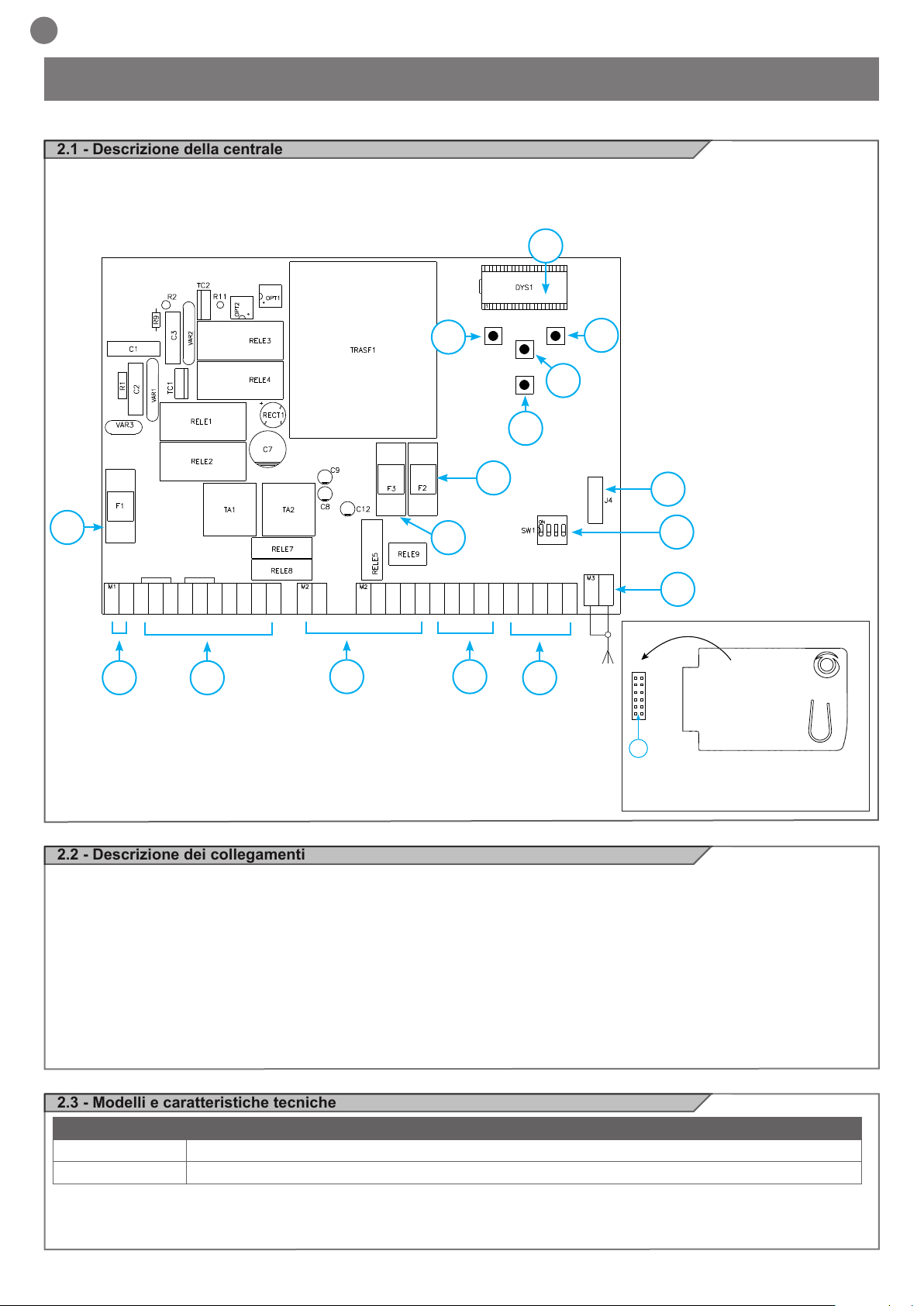
2.1 - Descrizione della centrale
La centrale CT202 è il più moderno ed efciente sistema di controllo
per i motori Key Automation, per l’apertura e la chiusura elettrica di
cancelli a battente.
Ogni altro uso improprio della centrale è vietato. La centrale CT202
è dotata di un display che permette una facile programmazione ed
il costante monitoraggio dello stato degli ingressi; inoltre la struttura
a menu permette una semplice impostazione dei tempi di lavoro e
delle logiche di funzionamento.
8
UP DOWN
9
MENU
+ -
SS
11
10
12
16
M
M
L
L1
N
1
2
1
L2
L1
L2
COURTESY L.
COM
COURTESY L.
FLASH
FLASH
24 Vac
24 Vac
EL
EL
3 4
COM
2
+24 Vdc
+ 24 TX PH
GND
14
EDGE
EDGE
2.2 - Descrizione dei collegamenti
1- Collegamenti alimentazione 230 Vac (120 Vac)
2- Collegamenti alimentazioni motori/condensatori/lampeggianti e luce di
cortesia
3- Collegamento alimentazioni 24 Vdc/Vac comandi e sicurezze
4- Collegamento sicurezze e indicazione Leds ROSSI EDGE PH2-PH1STOP
5- Collegamento comandi e indicazione Leds VERDI OPEN-CLOSE-
PED-SS
6- Connettore scheda radio ad innesto RX4X ( 4 canali)
7- Connettore antenna
8- LCD display
15
6
13
7
STOP
OPEN
CLOSE
PH2
PH1
PEDSSCOM
J4
5
6
9- Pulsante UP +
10- Pulsante MENU
11- Pulsante DOWN 12- Pulsante SS PASSO PASSO
13- Dip switch sicurezze
14- F3- Fusibile protezione accessori AC + elettroserratura
2 A rapido
15- F2- Fusibile protezione accessori DC 500 mA rapido
16- F1- Fusibile protezione linea 6,3 A rapido
RICEVENTE RX4X
USCITA 1 = PASSO-PASSO
USCITA 2 = PEDONALE
USCITA 3 = APRE
USCITA 4 = LUCI ON/OFF
2.3 - Modelli e caratteristiche tecniche
CODICE DESCRIZIONE
900CT202 Centrale per due motori 230V, per cancelli a battente
900CT202V120 Centrale per due motori 120V, per cancelli a battente
- Alimentazione protetta contro i cortocircuiti all’interno della centrale, sui motori e sugli accessori collegati.
- Rilevamento degli ostacoli durante la velocità di regime mediante
sensore di corrente.
4
- Apprendimento automatico dei tempi di lavoro.
- Disattivazione degli ingressi di sicurezza tramite dip switch: non
occorre ponticellare i morsetti relativi alla sicurezza non installata,
è sufciente disabilitare la funzione da dip switch.
Page 5
CARATTERISTICHE TECNICHE
Alimentazione (L-N) 230 Vac (+10% - 15%) 50-60 Hz 120 Vac (+10% - 15%) 50-60 Hz
Carico max motore 700 W + 700 W 700 W + 700 W
Uscita alimentazione accessori Vdc e alimentazione test dispositivi 24 Vdc 500 mA 24 Vdc 500 mA
Uscita alimentazione accessori Vac 24 Vac 1 A 24 Vac 1 A
Uscita luce di cortesia 230 Vac 25 W 120 Vac 25 W
Uscita lampeggiante 230 Vac 25 W 120 Vac 25 W
Uscita elettroserratura 12 Vac / 15 VA 12 Vac / 15 VA
Tempo di lavoro massimo con carico nominale Regolabile Regolabile
Tempo di pausa Regolabile 0-900 sec. Regolabile 0-900 sec.
Temperatura di funzionamento -20 °C + 55 °C -20 °C + 55 °C
Fusibili linea alimentazione
Fusibili accessori DC
Fusibili accessori AC ed elettroserratura
6,3AF 6,3AF
500mAF 500mAF
2AF 2AF
2.4 - Elenco cavi necessari
IT
Nell'impianto tipico i cavi necessari per i collegamenti dei vari dispositivi sono indicati nella tabella elenco cavi.
I cavi utilizzati devono essere adatti al tipo di installazione; ad esem-
pio si consiglia un cavo tipo H03VV-F per posa in ambienti interni
oppure H07RN-F se posato all'esterno.
SPECIFICHE TECNICHE CAVI ELETTRICI
Collegamento cavo limite massimo consentito
Linea elettrica alimentazione 1 x cavo 3 x 1,5 mm
Linea alimentazione motore 1 x cavo 4 x 1,5 mm
Lampeggiante, luce di cortesia
Antenna
1 x cavo 4 x 0,5 mm2 **
1 x cavo tipo RG58
Elettroserratura 1 x cavo 2 x 1 mm
Fotocellule trasmettitore 1 x cavo 2 x 0,5 mm
Fotocellule ricevitore 1 x cavo 4 x 0,5 mm
Bordo sensibile 1 x cavo 2 x 0,5 mm
Selettore a chiave 1 x cavo 4 x 0,5 mm
2
2
20 m *
20 m
20 m
20 m (consigliato < 5 m)
2
2
2
2
2
20 m
20 m
20 m
20 m
20 m
* Se il cavo di alimentazione supera i 30 m di lunghezza occorre utilizzare un cavo con sezione maggiore (3x2,5 mm2) ed è necessario
installare una messa a terra di sicurezza in prossimità dell’automazione
** In alternativa possono essere utilizzati due cavi 2 x 0,5 mm2
3 - VERIFICHE PRELIMINARI
Prima di installare il prodotto vericare e controllare i seguenti punti:
controllare che il cancello o la porta siano adatti ad essere automatizzati;
il peso e la dimensione del cancello o della porta devono rientrare
nei limiti d’impiego specicati per l’automazione su cui viene installato il prodotto;
controllare la presenza e la solidità degli arresti meccanici di sicurezza del cancello o della porta;
vericare che la zona di ssaggio del prodotto non sia soggetta ad
allagamenti;
condizioni di elevata acidità o salinità o la vicinanza a fonti di calore
potrebbero causare malfunzionamenti del prodotto;
in caso di condizioni climatiche estreme (per esempio in presenza di
neve, ghiaccio, elevata escursione termica, temperature elevate) gli
attriti potrebbero aumentare e quindi la forza necessaria per la mo-
vimentazione e lo spunto iniziale potrebbe essere superiori a quella
necessaria in condizioni normali;
controllare che la movimentazione manuale del cancello o della
porta sia uida e priva di zone di maggiore attrito o vi sia rischio di
deragliamento dello stesso;
controllare che il cancello o la porta siano in equilibrio e rimangano
quindi fermi se lasciati in qualsiasi posizione;
vericare che la linea elettrica a cui sarà collegato il prodotto sia
provvista di opportuna messa a terra di sicurezza e protetta da un
dispositivo magnetotermico e differenziale;
prevedere nella rete di alimentazione dell’impianto un dispositivo di
disconnessione con una distanza di apertura dei contatti che consenta la disconnessione completa nelle condizioni dettate dalla categoria di sovratensione III;
vericare che tutto il materiale utilizzato per l’installazione sia conforme alle normative vigenti.
5
Page 6
IT
2
3
4
1
1
2
TX
RX
NC
PH2
2
3
4
1
1
2
TX
RX
PH1
N
L
+24 Vdc
24 Vac
24 Vac
EL
EL
GND
+ 24 TX PH
EDGE
EDGE
PH2
PH1
STOP
OPEN
CLOSE
PEDSSCOM
L
N
UP DOWN
MENU
SS
COURTESY L.
COURTESY L.
FLASH
FLASH
OUTPUT
24 Vdc
OUTPUT
24 Vac
GND_12/24
AC/DC
GND
_
12/24
AC/DC
COM
OUT
GND_12/24
AC/DC
GND
_
12/24
AC/DC
COM
OUT
NC
M
1
M
2
COM
L1
L2
COM
L1
L2
M1
M2
4 - INSTALLAZIONE DEL PRODOTTO
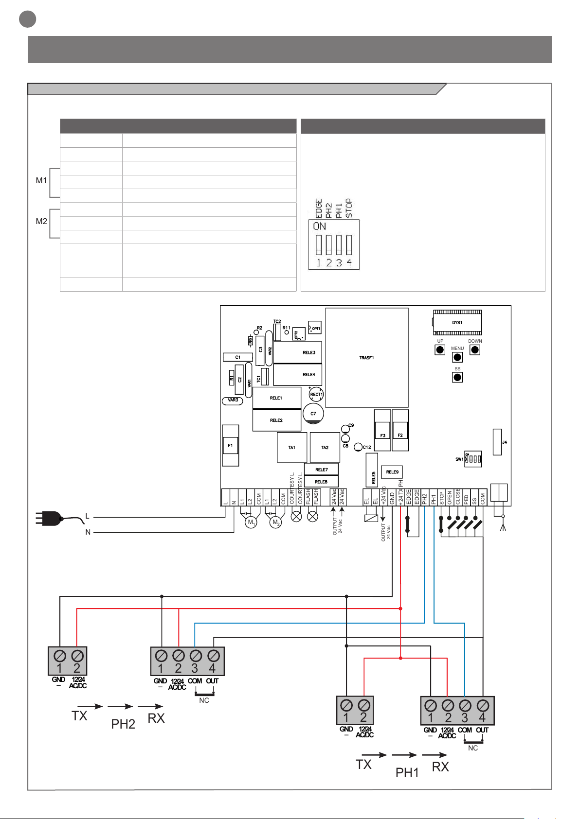
4.1 - Collegamenti elettrici
ATTENZIONE - Prima di effettuare i collegamenti vericare che la centrale non sia alimentata
CONNETTORE ALIMENTAZIONI E MOTORI
L Fase alimentazione 230 Vac (120 Vac) 50-60 Hz
N Neutro alimentazione 230 Vac (120 Vac) 50-60 Hz
L1 Fase motore
L2 Fase motore
COM Comune motore
L1 Fase motore
L2 Fase motore
COM Comune motore
COURTESY L. Lampada di cortesia, 230 Vac (120 Vac) 100 W,
uscita gestibile anche via radio ON-OFF (4°
canale radio selezionando fC.y. = 2, tC.y. = 0)
FLASH Lampeggiante, 230 Vac (120 Vac) 40 W
SELETTORE DIP SWITCH
Settato su “ON” disabilita gli ingressi EDGE, PH2, PH1, STOP.
Elimina la necessita’ di ponticellare gli ingressi su morsettiera.
ATTENZIONE - con dip switch in ON le sicurezze
collegate sono escluse
1 = COSTA
2 = FOTO 2
3 = FOTO 1
4 = STOP
6
Page 7

CONNETTORE ALIMENTAZIONI 24V, SICUREZZE E COMANDI
24 Vac Alimentazione accessori 24 Vac, 1 A
EL 12 Vac Uscita elettroserratura 12 Vac / 15 VA
+24 Vdc Alimentazione accessori positiva 24 Vdc, 500 mA
GND Alimentazione accessori negativa 24 Vdc, 500 mA
+ 24 Vdc
TX PHOTO
EDGE Costa sicurezza, ON/OFF contatto NC o resistiva 8K2 tra EDGE e EDGE (attenzione, con dip switch 1 in ON disabilita ingresso
PH2 Fotocellule (apertura) contatto NC tra PH2 e COM (attenzione, con dip switch 2 in ON disabilita ingresso sicurezza FOTOCEL-
PH1 Fotocellule (chiusura) contatto NC tra PH1 e COM (attenzione, con dip switch 3 in ON disabilita ingresso sicurezza FOTOCEL-
STOP STOP sicurezza contatto NC tra STOP e COM (attenzione, con dip switch 4 in ON disabilita ingresso sicurezza STOP)
OPEN Comando APERTURA contatto NA tra OPEN e COM
CLOSE Comando CHIUSURA contatto NA tra CLOSE e COM
PED Comando PEDONALE contatto NA tra PED e COM
SS Comando PASSO PASSO contatto NA tra SS e COM
COM Comune per ingressi PH1, PH2, STOP, OPEN, CLOSE, PED, SS
SHIELD Antenna - calza -
SIGNAL Antenna - segnale -
Alimentazione positiva fotocellule PH1, PH2; fototest selezionabile con parametro t.p.h
sicurezza COSTA)
LULA 2). La fotocellula interviene in qualsiasi momento durante l’apertura dell’automazione provocando l’immediato blocco
del moto, l’automazione continuerà l’apertura al ripristino del contatto; durante la chiusura la fotocellula interviene provocando
l’immediato blocco del moto, l’automazione invertirà la movimentazione in apertura a ripristino del contatto.
LULA 1). La fotocellula interviene in qualsiasi momento durante la chiusura dell’automazione provocando l’immediato blocco
del moto invertendo il senso di marcia; in apertura non interviene.
Tale ingresso viene considerato una sicurezza; il contatto può essere disattivato in qualsiasi momento bloccando immediatamente
l’automazione disabilitando qualsiasi funzione compresa la chiusura automatica
Contatto per la funzione UOMO PRESENTE. Il cancello APRE nche’ e’ premuto il contatto
Contatto per la funzione UOMO PRESENTE. Il cancello CHIUDE nche’ e’ premuto il contatto
Comando di apertura parziale dell’anta in base alla selezione software
Comando Apre/Stop/Chiude/Stop o in base alla selezione software
IT
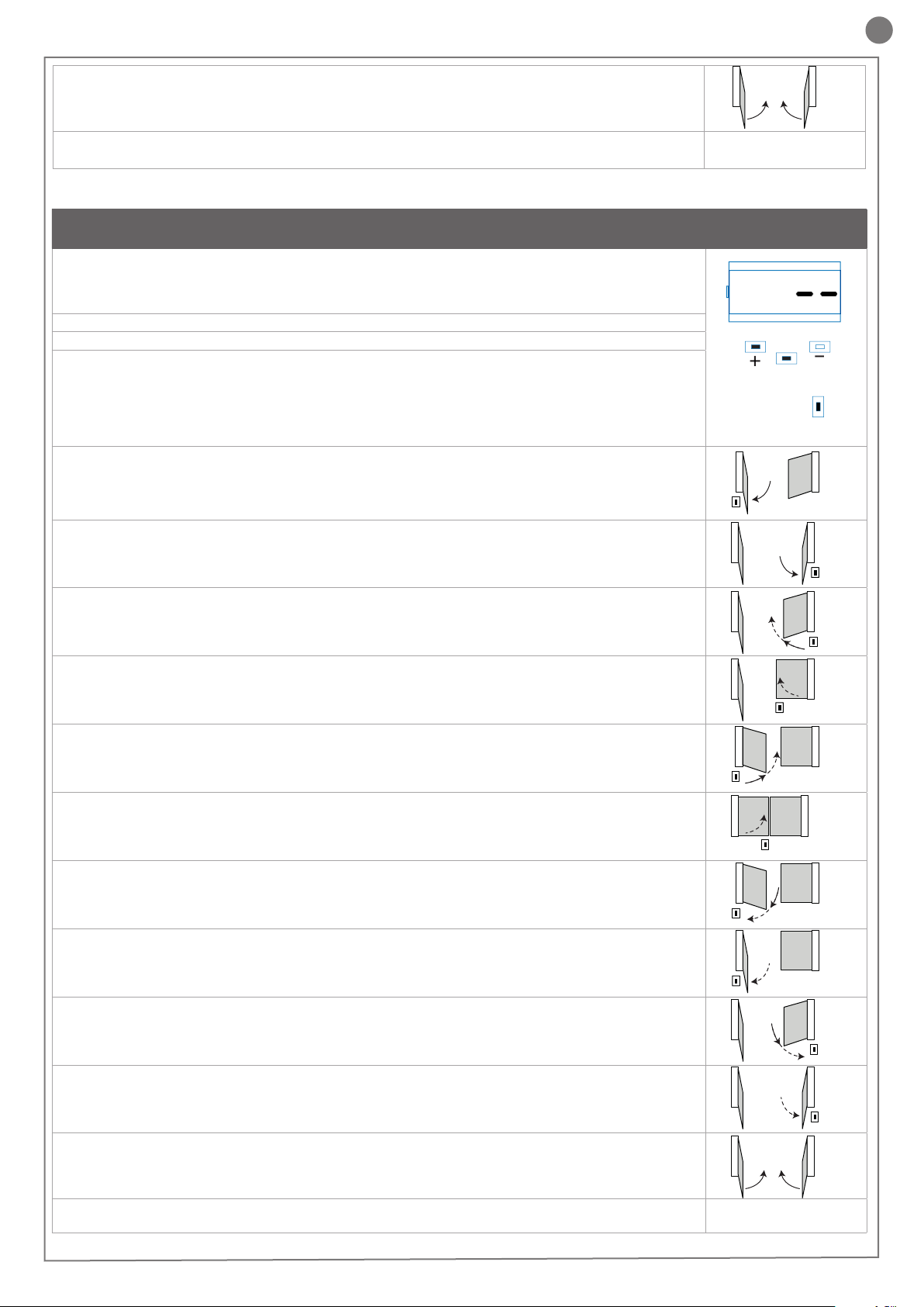
4.2 - Visualizzazione modalità normale
In “MODALITÀ NORMALE”, cioè quando normalmente si da alimentazione al sistema, il display LCD a 3 cifre mostra i seguenti messaggi di stato:
INDICAZIONI SIGNIFICATO
-OP
CL
SO
SC
HA
oP
Pe
-tC
-tP
L-LOP
LCL
Cancello chiuso o riaccensione dopo spegnimento
Cancello in apertura
Cancello in chiusura
Cancello fermato in apertura
Cancello fermato in chiusura
Cancello fermato da evento esterno
Cancello fermato senza richiusura automatica
Cancello in posizione di apertura pedonale senza richiusura automatica
Cancello aperto con richiusura temporizzata
Tratto lampeggiante conteggio in corso
Tratto sostituito da cifra 0..9 conto alla rovescia (ultimi 10s)
Cancello aperto pedonale con richiusura temporizzata
Tratto lampeggiante conteggio in corso
Tratto sostituito da cifra 0..9 conto alla rovescia (ultimi 10s)
Centrale pronta per apprendimento corsa
Apprendimento in apertura
Apprendimento in chiusura
7
Page 8
IT
Anomalie di funzionamento
In questo paragrafo vengono elencate alcune anomalie di funzionamento che si possono presentare.
ALLARME SOVRACCARICO IMPULSIVO La corrente del motore e’ incrementata molto rapidamente
EFO
ALLARME COSTA SICUREZZA La centrale ha rilevato un segnale dalla costa sicurezza
EED
ALLARME FOTOCELLULE Il fototest ha dato esito negativo
EPH
INTERVENTO TERMICA ELETTRONICA Mancato assorbimento di corrente del motore
Eth
Dopo aver rimosso la condizione di allarme, per cancellare ogni
segnalazione di errore basta semplicemente premere il tasto
1. L’anta ha colpito un ostacolo.
2. Ci sono attriti nello scorrimento dell’anta.
1. La costa di sicurezza e’ premuta.
2. La costa di sicurezza non e’ collegata correttamente.
1. Controllare i collegamenti delle fotocellule.
2. Vericare il corretto funzionamento delle fotocellule.
1. Vericare gli assorbimenti del motore.
2. Controllare che la corsa sia uida e libera dagli ostacoli.
“DOWN -” oppure premere il comando SS (PASSO PASSO).
Il display ripristina le normali indicazioni.
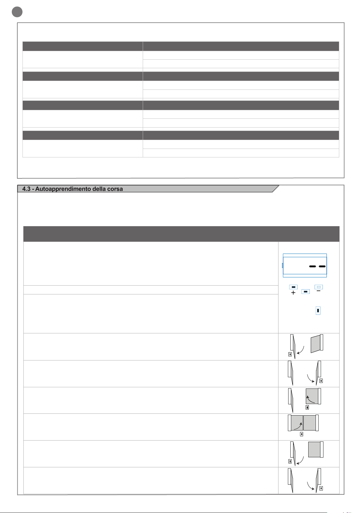
4.3 - Autoapprendimento della corsa
La prima volta che la centrale viene alimentata dev’essere eseguita
una procedura di auto apprendimento che permetta di rilevare dei
parametri fondamentali quali la lunghezza della corsa e dei rallentamenti.
Premendo i tasti + o - si può leggere, oltre allo stato della centrale
come da prima tabella del paragrafo 4.2, il conteggio delle manovre
eseguite. Nella visualizzazione delle manovre si alternano le migliaia, indicate senza i punti e le unità, indicate con dei punti tra di esse
(esempio: 50.000 = 50/0.0.0).
AUTOAPPRENDIMENTO DELLA CORSA E DEI PARAMETRI PRINCIPALI, CON
RALLENTAMENTI PREIMPOSTATI
I rallentamenti saranno quelli impostati da menù con la medesima percentuale sia in apertura che in chiusura.
ATTENZIONE: se si desidera programmare manualmente anche i rallentamenti passare direttamente
alla tabella successiva
1. ATTENZIONE: vericare l’esistenza e la solidità dei fermi meccanici, che sono obbligatori. I motori
devono obbligatoriamente andare in battuta meccanica
2. Portare manualmente le ante a metà della corsa
3. Premere CONTEMPORANEAMENTE i tasti UP + e MENU per più di 5 secondi no a visualizzare LOP e
prepararsi a premere (se necessario) il tasto DOWN (vedi gura).
Vericare che il motore M1 apra per primo, se così non fosse premere DOWN -, togliere la tensione e invertire i collegamenti di M1 e M2. Ripetere la procedura dal punto 3.
Se la prima manovra NON è un’apertura premere il tasto DOWN - per fermare l’autoapprendimento. Premere
quindi SS in modo da far ripartire l’acquisizione: l’anta riprende a muoversi in senso corretto.
4. Il motore M1 apre a bassa velocità no al raggiungimento della battuta meccanica di apertura.
Esattamente al raggiungimento della battuta meccanica di apertura inviare un comando di SS.
Parte in automatico il motore M2 in apertura. Se il motore M2 muove in chiusura fermare con DOWN - e
riprendere la movimentazione con SS (l’anta riprende a muoversi in senso corretto)
5. Il motore M2 apre a bassa velocità. Esattamente al raggiungimento della battuta meccanica di aper-
tura inviare un comando di SS. Dopo un paio di secondi il motore M2 parte automaticamente in chiusura a
velocità piena.
6. Quando il motore M2 raggiunge esattamente la posizione di chiusura, inviare un comando di SS. Il
motore M2 si ferma e parte in chiusura il motore M1.
UP
MENU
M1
SS
M1 M2
M1
M2
M2
DOWN
SS
4
5
SS
6
7. Quando il motore M1 raggiunge esattamente la posizione di chiusura, inviare un comando di SS. Il
motore M1 si ferma e riparte in apertura.
8. Quando il motore M1 raggiunge esattamente la posizione di apertura, inviare un comando di SS. Il
motore M1 si ferma e parte in apertura il motore M2.
9. Quando il motore M2 raggiunge esattamente la posizione di apertura, inviare un comando di SS. Il
motore M2 si ferma.
8
M1
SS
M1
SS
M1 M2
SS
M2
M2
7
8
9
SS
Page 9
IT
10. La movimentazione di M1 e M2 riprende in chiusura rispettando lo sfasamento delle ante impostato da
menu, ovvero il cancello si chiuderà autonomamente secondo la corsa programmata.
11. Effettuare alcune manovre di apertura, chiusura e stop improvviso vericando il sistema sia solido e che
non vi siano difetti di montaggio.
Tutti i parametri principali sono congurati di default dalla centrale. Per
personalizzare l’installazione procedere con il prossimo paragrafo 4.4.
Se la coppia non fosse sufciente per muovere l’anta eliminare i
rallentamenti da menu [LSI=0].
AUTOAPPRENDIMENTO DELLA CORSA E DEI PARAMETRI PRINCIPALI, CON
RALLENTAMENTI PERSONALIZZATI
I rallentamenti sono personalizzabili dall’utente, mediante la procedura sottindicata
1. ATTENZIONE: vericare l’esistenza e la solidità dei fermi meccanici, che sono obbligatori. I motori
devono obbligatoriamente andare in battuta meccanica
2. Portare manualmente le ante a metà della corsa
3. ATTENZIONE: entrare nel menù base per impostare il parametro LSI = p come da tabella al paragrafo 4.4
4. Premere CONTEMPORANEAMENTE i tasti UP + e MENU per più di 5 secondi no a visualizzare LOP e
prepararsi a premere (se necessario) il tasto DOWN (vedi gura).
Vericare che il motore M1 apra per primo, se così non fosse premere DOWN -, togliere la tensione e invertire
i collegamenti M1, M2. Ripetere la procedura dal punto 4.
Se la prima manovra NON è un’apertura premere il tasto DOWN - per fermare l’autoapprendimento. Premere
quindi SS in modo da far ripartire l’acquisizione: l’anta riprende a muoversi in senso corretto.
5. Il motore M1 apre a bassa velocità no al raggiungimento della battuta meccanica di apertura.
Esattamente al raggiungimento della battuta meccanica di apertura inviare un comando di SS.
Parte in automatico il motore M2 in apertura. Se il motore M2 muove in chiusura fermare con DOWN - e
riprendere la movimentazione con SS (l’anta riprende a muoversi in senso corretto).
6. Il motore M2 apre a bassa velocità. Esattamente al raggiungimento della battuta meccanica di aper-
tura inviare un comando di SS. Dopo un paio di secondi il motore M2 parte automaticamente in chiusura a
velocità piena.
7. Raggiunto il punto in cui si desidera inizi il rallentamento in chiusura del motore M2 inviare un
comando di SS. La movimentazione del motore M2 continua a velocità ridotta.
M1 M2
UP
SS
M1 M2
M1
MENU
M2
M2
10
DOWN
SS
5M1
6
SS
7
8. Quando il motore M2 raggiunge esattamente la posizione di chiusura, inviare un comando di SS. Il
motore M2 si ferma e parte in chiusura il motore M1.
9. Raggiunto il punto in cui si desidera inizi il rallentamento in chiusura del motore M1 inviare un
comando di SS. La movimentazione del motore M1 continua a velocità ridotta.
10. Quando il motore M1 raggiunge esattamente la posizione di chiusura, inviare un comando di SS. Il
motore M1 si ferma e riparte in apertura.
11. Raggiunto il punto in cui si desidera inizi il rallentamento in apertura del motore M1 inviare un
comando di SS. La movimentazione del motore M1 continua a velocità ridotta.
12. Quando il motore M1 raggiunge esattamente la posizione di apertura, inviare un comando di SS. Il
motore M1 si ferma e parte in apertura il motore M2.
13. Raggiunto il punto in cui si desidera inizi il rallentamento in apertura del motore M2 inviare un
comando di SS. La movimentazione del motore M2 continua a velocità ridotta.
14. Quando il motore M2 raggiunge esattamente la posizione di apertura, inviare un comando di SS. Il
motore M2 si ferma.
M1
M1
SS
M1
SS
M1
SS
M1
SS
M1
M1 M2
SS
M2
M2
M2
M2
M2
M2
SS
10
SS
8
9
11
12
13
14
SS
15. La movimentazione di M1 e M2 riprende in chiusura rispettando lo sfasamento delle ante impostato
M1 M2
15
da menu, ovvero il cancello si chiuderà autonomamente secondo la corsa programmata.
16. Effettuare alcune manovre di apertura, chiusura e stop improvviso vericando il sistema sia solido e che
non vi siano difetti di montaggio.
Tutti i parametri principali sono congurati di default dalla centrale. Per personalizzare l’installazione procedere con il prossimo paragrafo 4.4.
9
Page 10
IT
n
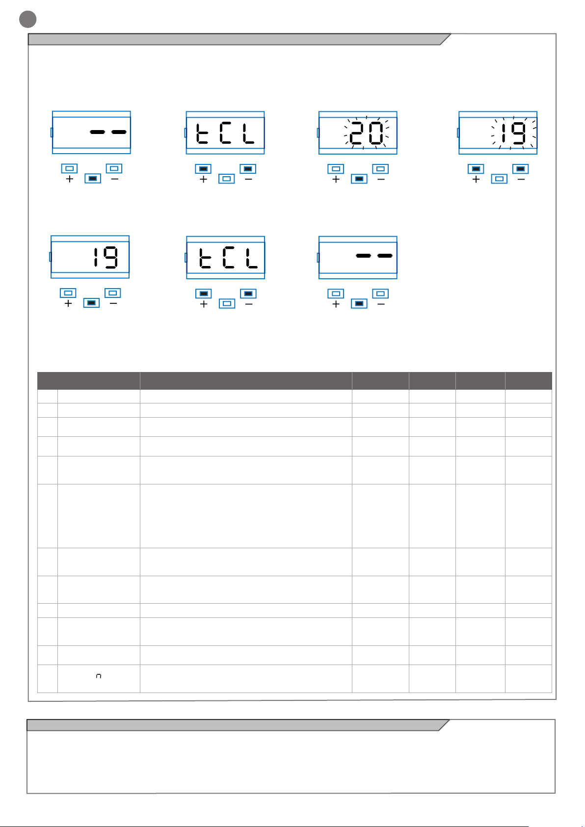
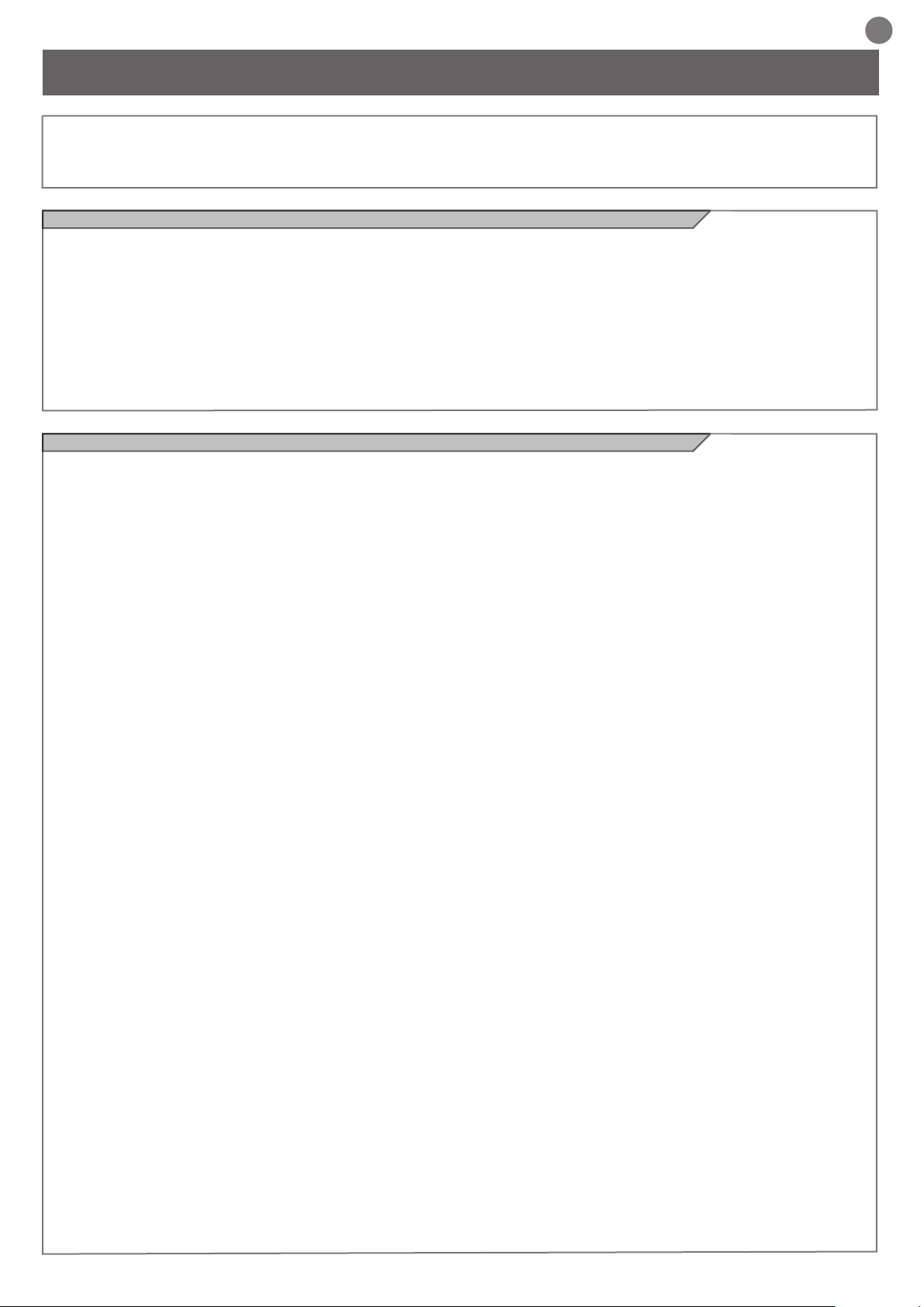
4.4 - Personalizzazione dell’impianto - MENU BASE
In caso di necessità è possibile selezionare un MENU BASE che
permette di modicare i parametri base della unità di controllo. Per
selezionare il MENU BASE procedere come sotto riportato.
Esempio di modica di un parametro del MENU BASE
ATTENZIONE: per portarsi con certezza allo stato di visualizzazione denito come FUNZIONE NORMALE, punto di partenza per ac-
cedere al MENU BASE, premere 2 volte il tasto MENU
UP
Premere il tasto MENU per 1
secondo per entrare nel menu’
base.
UP
Premere il tasto MENU per 1
secondo no a visualizzare il
valore sso per salvare il valore modicato oppure MENU
velocemente per uscire senza
salvare.
DOWN
MENU
DOWN
MENU
PARAMETRI DESCRIZIONE DEFAULT MIN MAX UNITA’
Tempo richiusura automatica (0 = disabilitato) 20 0 900 s
Tempo richiusura dopo il transito (0 = disabilitato) 0 0 30 s
Sensibilità su ostacolo
(0 = disabilitato)
Forza motore (coppia a regime) 100 10 100
Modalità rallentamento
0 = rallentamento 1/3 (lento)
1 = rallentamento 2/3 (veloce)
Congurazione SS:
0 = Normale (AP-ST-CH-ST-AP-ST…)
1 = Alternato STOP (AP-ST-CH-AP-ST-CH…)
2 = Alternato (AP-CH-AP-CH…)
3 = Condominiale – timer
4 = Condominiale con richiusura immediata
Comportamento dopo black out
0 = nessuna azione, rimane com’era
1 = Chiusura
Soft start (partenza rallentata)
0 = disabilitato
1 = abilitato
Ritardo seconda anta 2 0 300 s
Ampiezza rallentamento
P = personalizzato da apprendimento
0...100% = percentuale della corsa
Antislittamento: prolunga il tempo di lavoro impostato
(utile in zone soggette a forte vento)
Numero motori
1 = 1 motore
2 = 2 motori
10
11
12
1
2
3
4
5
6
7
8
9
TCL
ttr
SEI
trq
SSL
SbS
bLt
SST
dLY
LSI
ASL
nMt
UP
Entrati nel MENU BASE pre-
mere i tasti + e – per scorrere
le funzioni.
UP
Premere i tasti + o – per scorrere le funzioni per modicare
altri parametri.
DOWN
MENU
DOWN
MENU
UP UP
Per entrare in modica valore,
premere il tasto MENU per 1
secondo nche’ il valore lampeggia velocemente
UP
Premere il tasto MENU velocemente per uscire dal menu.
DOWN DOWN
MENU MENU
DOWN
MENU
0 0 100
0 0 1
0 0 4
0 0 1
0 0 1
15 0 100
0 0 300 s
1 1 2
Premere i tasti + e – per modicare il valore.
% (step
da 1)
% (step
da 10)
% (step
da 1)
4.5 - Innesto ricevente radio
Innestare la ricevente radio facendo attenzione alla direzione come
indicato nella gura al paragrafo 2.1.
Per la programmazione seguire le istruzioni della ricevente sapendo
10
che le 4 uscite attivabili sono: USCITA 1 = PASSO PASSO,
USCITA 2 = PEDONALE, USCITA 3 = APRE, USCITA 4 = CHIUDE.
Page 11

5 - COLLAUDO E MESSA IN SERVIZIO DELL’AUTOMAZIONE
IT
Il collaudo dell’impianto va eseguito da un tecnico qualicato che
deve effettuare le prove richieste dalla normativa di riferimento in
funzione dei rischi presenti, vericando il rispetto di quanto previsto
5.1 - Collaudo
Tutti i componenti dell’impianto devono essere collaudati seguendo
le procedure indicate nei rispettivi manuali di istruzioni;
controllare che siano rispettate le indicazioni del Capitolo 1 – Avvertenze per la sicurezza;
controllare che il cancello o la porta si possano muovere liberamente una volta sbloccata l’automazione e che siano in equilibrio e rimangano quindi fermi se lasciati in qualsiasi posizione;
5.2 - Messa in servizio
A seguito del positivo collaudo di tutti (e non solo di alcuni) i dispositivi dell’impianto si può procedere con la messa in servizio;
è necessario realizzare e conservare per 10 anni il fascicolo tecnico
dell’impianto che dovrà contenere lo schema elettrico, il disegno o
foto dell’impianto, l’analisi dei rischi e le soluzioni adottate, la dichiarazione di conformità del fabbricante di tutti i dispositivi collegati,
il manuale istruzioni di ogni dispositivo e il piano di manutenzione
dell’impianto;
dalle normative, in particolare la norma EN12445 che indica i metodi di prova per gli automatismi per porte e cancelli.
controllare il corretto funzionamento di tutti i dispositivi collegati (fotocellule, bordi sensibili, pulsanti di emergenza, altro) effettuando
delle prove di apertura, chiusura e arresto del cancello o della porta
tramite i dispositivi di comando collegati (trasmettitori, pulsanti, selettori);
effettuare le misurazioni della forza d’impatto come previsto dalla
normativa EN12445 regolando le funzioni di velocità, forza motore e
rallentamenti della centrale nel caso in cui le misurazioni non diano i
risultati desiderati no a trovare il giusto settaggio.
realizzare e consegnare all’utilizzatore nale la dichiarazione di
conformità , le istruzioni e avvertenze d’uso per l’utilizzatore nale e
il piano di manutenzione dell’impianto;
accertarsi che l’utilizzatore abbia compreso il corretto funzionamento automatico, manuale e di emergenza dell’automazione;
informare anche in forma scritta l’utilizzatore nale sui pericoli e rischi ancora presenti;
ssare sul cancello o la porta una targa indicante i dati dell’automazione, il nome del responsabile della messa in servizio, il numero di
matricola e l’anno di costruzione, il marchio CE;
ssare una targa che indichi le operazioni necessarie per sbloccare
manualmente l’impianto;
ATTENZIONE - dopo la rilevazione di un ostacolo, il cancello o la
porta si ferma in apertura e viene esclusa la chiusura automatica;
per riprendere il movimento bisogna premere il pulsante di comando o usare il trasmettitore.
11
Page 12
IT
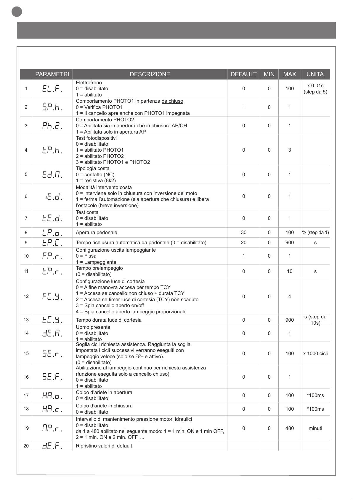
PARAMETRI DESCRIZIONE DEFAULT MIN MAX UNITA’
1
EL.F.
Elettrofreno
0 = disabilitato
1 = abilitato
0 0 100
x 0.01s
(step da 5)
2
SP.h.
Comportamento PHOTO1 in partenza da chiuso
0 = Verica PHOTO1
1 = Il cancello apre anche con PHOTO1 impegnata
1 0 1
3
Ph.2.
Comportamento PHOTO2
0 = Abilitata sia in apertura che in chiusura AP/CH
1 = Abilitata solo in apertura AP
0 0 1
4
tP.h.
Test fotodispositivi
0 = disabilitato
1 = abilitato PHOTO1
2 = abilitato PHOTO2
3 = abilitato PHOTO1 e PHOTO2
0 0 3
5
ed.M.
Tipologia costa
0 = contatto (NC)
1 = resistiva (8k2)
0 0 1
6
iE.D.
Modalità intervento costa
0 = interviene solo in chiusura con inversione del moto
1 = ferma l’automazione (sia apertura che chiusura) e libera
l’ostacolo (breve inversione)
0 0 1
7
tE.D.
Test costa
0 = disabilitato
1 = abilitato
0 0 1
8
LP.o.
Apertura pedonale 30 0 100 % (step da 1)
9
TP.C.
Tempo richiusura automatica da pedonale (0 = disabilitato) 20 0 900 s
10
FP.r.
Congurazione uscita lampeggiante
0 = Fissa
1 = Lampeggiante
1 0 1
11
tP.r.
Tempo prelampeggio
(0 = disabilitato)
0 0 10 s
12
FC.Y.
Congurazione luce di cortesia
0 = A ne manovra accesa per tempo TCY
1 = Accesa se cancello non chiuso + durata TCY
2 = Accesa se timer luce di cortesia (TCY) non scaduto
3 = Spia cancello aperto on/off
4 = Spia cancello aperto lampeggio proporzionale
0 0 4
13
tC.Y.
Tempo durata luce di cortesia 0 0 900
s (step da
10s)
14
dE.A.
Uomo presente
0 = disabilitato
1 = abilitato
0 0 1
15
se.r.
Soglia cicli richiesta assistenza. Raggiunta la soglia
impostata i cicli successivi verranno eseguiti con
lampeggio veloce (solo se FPr è attivo).
(0 = disabilitato)
0 0 100 x 1000 cicli
16
se.f.
Abilitazione al lampeggio continuo per richiesta assistenza
(funzione eseguita solo a cancello chiuso).
0 = disabilitato
1 = abilitato
0 0 1
17
HA.o.
Colpo d’ariete in apertura
0 = disabilitato
0 0 100 *100ms
18
HA.c.
Colpo d’ariete in chiusura
0 = disabilitato
0 0 100 *100ms
19
mp.r.
Intervallo di mantenimento pressione motori idraulici
0 = disabilitato
da 1 a 480 abilitato nel seguente modo: 1 = 1 min. ON e 1 min OFF,
2 = 1 min. ON e 2 min. OFF, ...
0 0 480 minuti
20
de.f.
Ripristino valori di default
n
n
6 - APPROFONDIMENTI - MENU AVANZATO
Il MENU AVANZATO permette di personalizzare ulteriormente l’im-
pianto modicando dei parametri non accessibili dal menu base.
Per accedere al menu AVANZATO si preme e si tiene premuto per
5 secondi il tasto MENU.
Per modicare i parametri del MENU AVANZATO si procede come
indicato per il MENU BASE.
Per impostare i valori di default: 1) entrare in programmazione
avanzata; 2) selezionare il parametro “def”; 3) attivare il modo mo-
dica (si visualizza “0”); 4) accettare la modica (premere “MENU”
12
e mantenerlo premuto). A questo punto si deve visualizzare un
conto alla rovescia d80,d79...,d01 no a “don“. Alla ne rilasciare
il tasto.
Page 13

7 - ISTRUZIONI ED AVVERTENZE DESTINATE ALL’UTILIZZATORE FINALE
IT
Key Automation S.r.l. produce sistemi per l’automazione di cancelli,
porte garage, porte automatiche, serrande, barriere per parcheggi e stradali. Key Automation non è però il produttore della vostra
automazione, che è invece il risultato di un’opera di analisi, valutazione, scelta dei materiali, e realizzazione dell’impianto eseguita
dal vostro installatore di ducia. Ogni automazione è unica e solo il
vostro installatore possiede l’esperienza e la professionalità necessarie ad eseguire un impianto secondo le vostre esigenze, sicuro ed
afdabile nel tempo, e soprattutto a regola d’arte, rispondente cioè
alle normative in vigore. Anche se l’automazione in vostro possesso
soddisfa il livello di sicurezza richiesto dalle normative, questo non
esclude l’esistenza di un “rischio residuo”, cioè la possibilità che si
possano generare situazioni di pericolo, solitamente dovute ad un
utilizzo incosciente o addirittura errato, per questo motivo desideriamo darvi alcuni consigli sui comportamenti da seguire:
• prima di usare per la prima volta l’automazione, fatevi spiegare
dall’installatore l’origine dei rischi residui;
• conservate il manuale per ogni dubbio futuro e consegnatelo ad un
eventuale nuovo proprietario dell’automazione;
• un uso incosciente ed improprio dell’automazione può farla diventare pericolosa: non comandate il movimento dell’automazione se
nel suo raggio di azione si trovano persone, animali o cose;
• se adeguatamente progettato un impianto di automazione garantisce un alto grado di sicurezza, impedendo con i suoi sistemi di rilevazione il movimento in presenza di persone o cose, e garantendo
un’attivazione sempre prevedibile e sicura. È comunque prudente
vietare ai bambini di giocare in prossimità dell’automazione e per
evitare attivazioni involontarie non lasciare i telecomandi alla loro
portata.
• non appena notate qualunque comportamento anomalo da parte dell’automazione, togliete alimentazione elettrica all’impianto ed
eseguite lo sblocco manuale. Non tentate da soli alcuna riparazio-
ne, ma richiedete l’intervento del vostro installatore di ducia: nel
frattempo l’impianto può funzionare come un’apertura non automatizzata, una volta sbloccato il motoriduttore con apposita chiave di
sblocco data in dotazione con l’impianto. Con le sicurezze fuori uso
è necessario far riparare quanto prima l’automatismo;
• in caso di rotture o assenza di alimentazione: attendete l’intervento
del vostro installatore, o il ritorno dell’energia elettrica se l’impianto
non è dotato di batterie tampone, l’automazione può essere azionata come una qualunque apertura non automatizzata. Per fare ciò è
necessario eseguire lo sblocco manuale;
• Manutenzione: Come ogni macchinario la vostra automazione
ha bisogno di una manutenzione periodica afnché possa funzionare più a lungo possibile ed in completa sicurezza. Concordate
con il vostro installatore un piano di manutenzione con frequenza
periodica; Key Automation consiglia un intervento ogni 6 mesi per
un normale utilizzo domestico, ma questo periodo può variare in
funzione dell’intensità d’uso. Qualunque intervento di controllo, manutenzione o riparazione deve essere eseguito solo da personale
qualicato.
• Non modicate l’impianto ed i parametri di programmazione e di
regolazione dell’automazione: la responsabilità è del vostro installatore.
• Il collaudo, le manutenzioni periodiche e le eventuali riparazioni
devono essere documentate da chi le esegue e i documenti conservati dal proprietario dell’impianto.
Gli unici interventi che vi sono possibili e vi consigliamo di effettuare periodicamente sono la pulizia dei vetrini delle fotocellule e la
rimozione di eventuali foglie o sassi che potrebbero ostacolare l’automatismo. Per impedire che qualcuno possa azionare il cancello o
la porta, prima di procedere, ricordatevi di sbloccare l’automatismo
e di utilizzare per la pulizia solamente un panno leggermente inumidito con acqua.
• Al termine della vita dell’automazione, assicuratevi che lo smaltimento sia eseguito da personale qualicato e che i materiali venga-
no riciclati o smaltiti secondo le norme valide a livello locale.
Se il vostro trasmettitore dopo qualche tempo vi sembra funzionare peggio, oppure non funzionare affatto, potrebbe semplicemente
dipendere dall’esaurimento della pila (a seconda dell’uso, possono
trascorrere da diversi mesi no ad oltre un anno). Ve ne potete accorgere dal fatto che la spia di conferma della trasmissione non si
accende, oppure si accende solo per un breve istante.
Le pile contengono sostanze inquinanti: non gettarle nei riuti comuni ma utilizzare i metodi previsti dai regolamenti locali.
Vi ringraziamo per aver scelto Key Automation S.r.l. e vi invitiamo
a visitare il nostro sito internet www.keyautomation.it per ulteriori
informazioni.
• sblocco e movimento manuale: prima di eseguire questa operazione porre attenzione che lo sblocco può avvenire solo quando
l’anta è ferma.
13
Page 14

EN
TABLE OF CONTENTS
1
Safety warnings
pag. 15
2
2.1
2.2
2.3
2.4
Product Introduction
Description of the control unit
Description of the connections
Models and technical characteristics
List of cables required
pag. 16
pag. 16
pag. 16
pag. 16
pag. 17
3
Preliminary Checks
pag. 17
4
4.1
4.2
4.3
4.4
4.5
Installing the Product
Electric connections
Display during normal operation
Autolearning of the travel stroke
Customising the system - BASIC MENU
Connecting the radio receiver
pag. 18
pag. 18
pag. 19
pag. 20
pag. 22
pag. 22
5
5.1
5.2
Testing and commissioning
Testing
Commissioning
pag. 23
pag. 23
pag. 23
6
Further details - ADVANCED MENU
pag. 24
7
Instructions and warnings for the
nal user
pag. 25
8
EC declaration of conformity
pag. 87
14
Page 15

1 - SAFETY WARNINGS
EN
CAUTION – to ensure personal safety it is important
to follow these instructions and keep them for future
reference.
Read the instructions carefully before proceeding with installation.
The design and manufacture of the devices making
up the product and the information in this manual are
compliant with current safety standards. However,
incorrect installation or programming may cause serious injury to those working on or using the system.
Compliance with the instructions provided here when
installing the product is therefore extremely impor-
tant.
If in any doubt regarding installation, do not proceed and contact the
Key Automation Technical Service for clarications.
Under European legislation, an automatic door or
gate system must comply with the standards envisaged in the Directive 2006/42/EC (Machinery Directive)
and in particular standards EN 12445; EN 12453; EN
12635 and EN 13241-1, which enable declaration of
presumed conformity of the automation system.
Therefore, nal connection of the automation system to the electrical mains, system testing, commissioning and routine maintenance
must be performed by skilled, qualied personnel, in observance of
the instructions in the “Testing and commissioning the automation
system” section.
The aforesaid personnel are also responsible for the tests required
to verify the solutions adopted according to the risks present, and
for ensuring observance of all legal provisions, standards and regulations, with particular reference to all requirements of the EN 12445
standard which establishes the test methods for testing door and
gate automation systems.
WARNING - Before starting installation, perform the
following checks and assessments:
ensure that every device used to set up the automation system is
suited to the intended system overall. For this purpose, pay special
attention to the data provided in the “Technical specications” section. Do not proceed with installation if any one of these devices is
not suitable for its intended purpose;
check that the devices in the kit are sufcient to guarantee system
safety and functionality;
perform a risk assessment, including a list of the essential safety
requirements as envisaged in Annex I of the Machinery Directive,
specifying the solutions adopted. The risk assessment is one of the
documents included in the automation system’s technical le. This
must be compiled by a professional installer.
Considering the risk situations that may arise during
installation phases and use of the product, the automation system must be installed in compliance with
the following safety precautions:
should this occur, disconnect the power supply immediately and
contact a Key Automation Service Centre. Use of the automation
system in these conditions may cause hazards;
never place automation system components near to sources of heat
or expose them to naked ames. This may damage system components and cause malfunctions, re or hazards.
All operations requiring opening of the protective housings of various automation system components must be performed with the
control unit disconnected from the power supply. If the disconnect
device is not in a visible location, afx a notice stating: “MAINTENANCE IN PROGRESS”;
all devices must be connected to an electric power line equipped
with an earthing system.
The product cannot be considered to provide effective protection
against intrusion. If effective protection is required, the automation
system must be combined with other devices;
the product may not be used until the automation system “commissioning” procedure has been performed as specied in the “Automation system testing and commissioning” section.
The system power supply line must include a circuit breaker device
with a contact gap allowing complete disconnection in the condi-
tions specied by class III overvoltage;
use unions with IP55 or higher protection when connecting hoses,
pipes or raceways;
the electrical system upstream of the automation system must comply with the relevant regulations and be constructed to good workmanship standards;
users are advised to install an emergency stop button close to the
automation system (connected to the control PCB STOP input) to
allow the gate or door to be stopped immediate in case of danger;
this device product is not intended for use by persons (including
children) with impaired physical, sensory or mental capacities, or
with lack of experience or skill, unless a person responsible for their
safety provides surveillance or instruction in use of the device;
children must be supervised to ensure that they do not play with the
equipment.
WARNING - The automation system component
packaging material must be disposed of in full observance of current local waste disposal legislation.
WARNING - The data and information in this manual
are subject to modication at any time, with no obligation on the part of Key Automation S.r.l. to provide
notice.
never make any modications to part of the automation system
other than those specied in this manual. Operations of this type
can only lead to malfunctions. The manufacturer declines all liability
for damage caused by unauthorised modications to products.
do not allow parts of the automation system to be immersed in water
or other liquids. During installation ensure that no liquids are able to
enter the various devices;
15
Page 16
EN
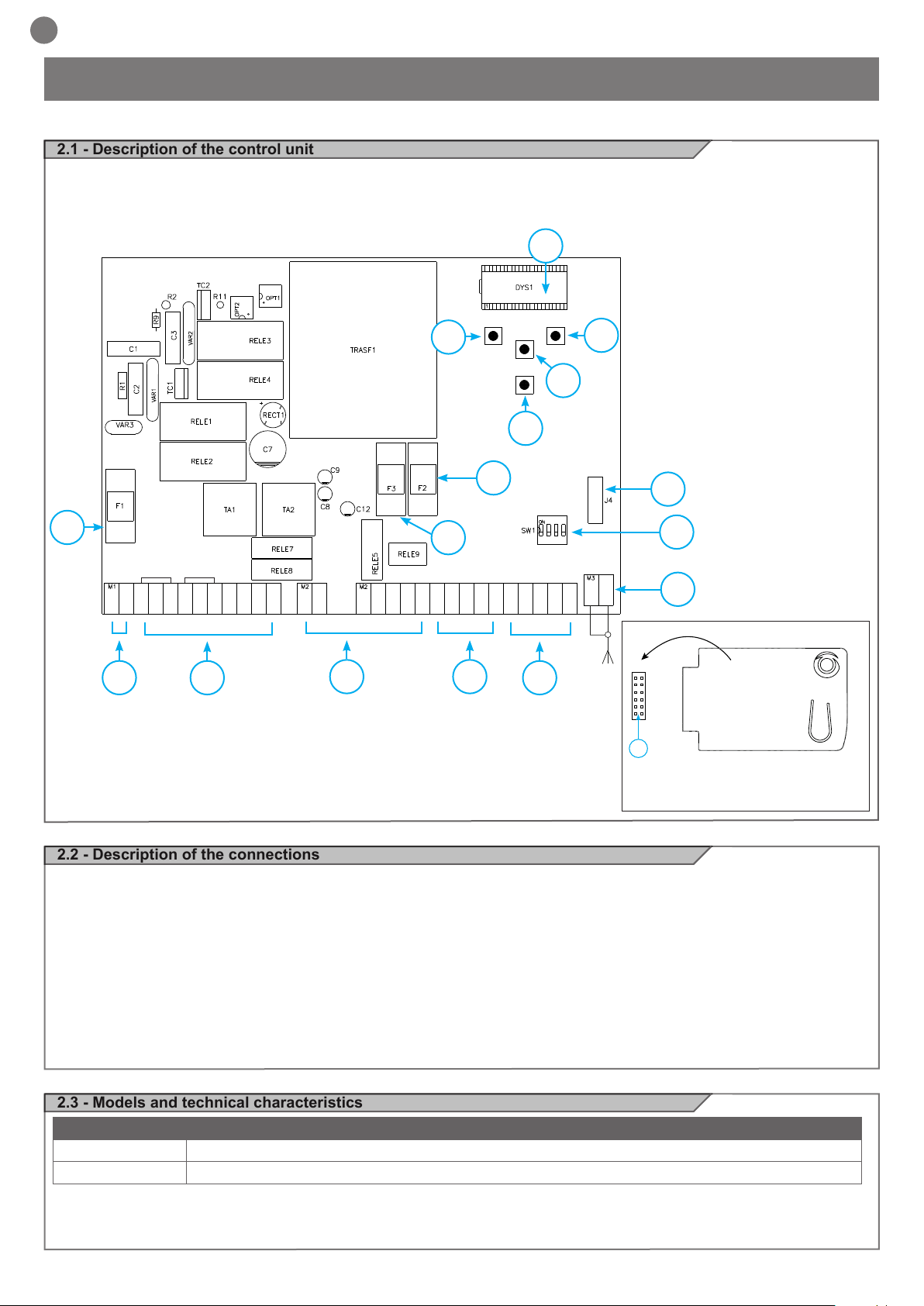
2 - INTRODUCING THE PRODUCT
2.1 - Description of the control unit
The CT202 control unit is a state-of-the-art efcient control system for
Key Automation motors, for electrical opening and closing of swing
gates.
Any other use is deemed improper and is strictly prohibited. The
CT202 control unit is equipped with a display to enable simple pro-
gramming and constant monitoring of input status; the menu structure also enables easy entry of work times and operating logic.
8
UP DOWN
9
MENU
+ -
SS
11
10
12
16
M
M
L
L1
N
1
2
1
L2
L1
L2
COURTESY L.
COM
COURTESY L.
FLASH
FLASH
24 Vac
24 Vac
EL
EL
3 4
COM
2
+24 Vdc
+ 24 TX PH
GND
14
EDGE
2.2 - Description of the connections
1- 230 Vac (120 Vac) power supply connections
2- Power supply connections for motors/capacitors/ashing lights
and courtesy light
3- Connection of 24 Vdc/Vac power supplies for controls and safety
devices
4- Connection of safety devices and signalling Leds RED EDGE
PH2-PH1-STOP
5- Connection of control devices and signalling Leds GREEN
OPEN-CLOSE-PED-SS
6- Connector for snap-t RX4X radio board ( 4 channel)
7- Antenna connector
15
6
13
7
STOP
OPEN
CLOSE
EDGE
PH2
PH1
PEDSSCOM
J4
5
6
8- LCD display
9- UP + pushbutton
10- MENU pushbutton
11- DOWN - pushbutton
12- SS STEP STEP pushbutton
13- Safety device dip switch
14- F3- Safety fuse for AC accessories + electric lock
2 A quick acting
15- F2- Safety fuse for DC accessories 500 mA quick acting
16- F1- Safety fuse for power line 6.3 A quick acting
RX4X RECEIVER
OUTPUT 1 = STEP-STEP
OUTPUT 2 = PEDESTRIAN
OUTPUT 3 = OPEN
OUTPUT 4 = LIGHTS ON/OFF
2.3 - Models and technical characteristics
CODE DESCRIPTION
900CT202 Control unit for two 230V motors, for swing gates
900CT202V120 Control unit for two 120V motors, for swing gates
- Power supply with protection against short-circuits inside the control unit, on motors and on the connected accessories.
- Obstacle detection during travel at normal speed by means of current sensor.
16
- Automatic learning of working times.
- Safety device deactivation by means of dip switches: there is no
need to bridge the terminals of safety devices which are not installed - the function is simply disabled by means of a dip switch.
Page 17
TECHNICAL SPECIFICATIONS:
Power supply (L-N) 230 Vac (+10% - 15%) 50-60 Hz 120 Vac (+10% - 15%) 50-60 Hz
Max motor load 700 W + 700 W 700 W + 700 W
Output for Vdc accessories power and device test power 24 Vdc 500 mA 24 Vdc 500 mA
Output for Vac accessories power 24 Vac 1 A 24 Vac 1 A
Courtesy light output 230 Vac 25 W 120 Vac 25 W
Flashing light output 230 Vac 25 W 120 Vac 25 W
Electric lock output 12 Vac / 15 VA 12 Vac / 15 VA
Maximum work time with settable nominal load Adjustable Adjustable
Pause time Adjustable 0-900 sec. Adjustable 0-900 sec.
Operating temperature -20 °C + 55 °C -20 °C + 55 °C
Power supply line fuses
Accessory fuses DC
Accessory fuses AC and electric lock
6,3AF 6,3AF
500mAF 500mAF
2AF 2AF
2.4 - List of cables required
EN
The cables required for connection of the various devices in a standard system are listed in the cables list table.
The cables used must be suitable for the type of installation; for
example, an H03VV-F type cable is recommended for indoor applications, while H07RN-F is suitable for outdoor applications.
ELECTRIC CABLE TECHNICAL SPECIFICATIONS:
Connection cable maximum allowable limit
Power supply line 1 x cable 3 x 1,5 mm
Motor power supply line 1 x cable 4 x 1,5 mm
Flashing light, courtesy light
Antenna
Electric lock
1 x cable 4 x 0,5 mm2 **
1 x cable type RG58
1 x cable 2 x 1 mm
Transmitter photocells 1 x cable 2 x 0,5 mm
Receiver photocells 1 x cable 4 x 0,5 mm
Sensitive edge 1 x cable 2 x 0,5 mm
Key-switch 1 x cable 4 x 0,5 mm
2
2
20 m *
20 m
20 m
20 m (advised < 5 m)
2
2
2
2
2
20 m
20 m
20 m
20 m
20 m
* If the power cable is longer than 30 m, a cable with a larger cross-section is required (3x2.5 mm2) and safety earthing is necessary in the
vicinity of the automation.
** Two cables of 2 x 0.5 mm2 can be used as an alternative
3 - PRELIMINARY CHECKS
Before installing the product, perform the following checks and inspections:
check that the gate or door is suitable for automation;
the weight and size of the gate or door must be within the operating
limits specied for the automation system in which the product is
installed;
check that the gate or door has rm, effective mechanical safety
stops;
make sure that the product xing zone is not subject to ooding;
high acidity or salinity or nearby heat sources might cause the product to malfunction;
in case of extreme weather conditions (e.g. snow, ice, wide temperature variations or high temperatures), friction may increase, causing a corresponding rise in the force needed to operate the system;
the starting torque may therefore exceed that required in normal
conditions;
check that when operated by hand the gate or door moves smoothly
without any areas of greater friction or derailment risk;
check that the gate or door is well balanced and will therefore remain stationery when released in any position;
check that the electricity supply line to which the product is to be
connected is suitably earthed and protected by an overload and differential safety breaker device;
the system power supply line must include a circuit breaker device
with a contact gap allowing complete disconnection in the condi-
tions specied by class III overvoltage;
ensure that all the material used for installation complies with the
relevant regulatory standards.
17
Page 18

EN
2
3
4
1
1
2
TX
RX
NC
PH2
2
3
4
1
1
2
TX
RX
PH1
N
L
+24 Vdc
24 Vac
24 Vac
EL
EL
GND
+ 24 TX PH
EDGE
EDGE
PH2
PH1
STOP
OPEN
CLOSE
PEDSSCOM
L
N
UP DOWN
MENU
SS
COURTESY L.
COURTESY L.
FLASH
FLASH
OUTPUT
24 Vdc
OUTPUT
24 Vac
GND_12/24
AC/DC
GND
_
12/24
AC/DC
COM
OUT
GND_12/24
AC/DC
GND
_
12/24
AC/DC
COM
OUT
NC
M
1
M
2
COM
L1
L2
COM
L1
L2
M1
M2
4 - PRODUCT INSTALLATION
4.1 - Electrical connections
WARNING - Before making the connections, ensure that the control unit is not powered up.
POWER SUPPLY CONNECTOR AND MOTOR
L 230 Vac (120 Vac) 50-60 Hz power supply phase
N 230 Vac (120 Vac) 50-60 Hz power supply
neutral
L1 Motor phase
L2 Motor phase
COM Motor common
L1 Motor phase
L2 Motor phase
COM Motor common
COURTESY L. Courtesy light, 230 Vac (120 Vac) 100 W, output
controllable also via radio ON-OFF command
(radio channel 4 selecting fC.y. = 2, tC.y. = 0 )
FLASH Flashing light, 230 Vac (120 Vac) 40 W
POWER SUPPLY CONNECTOR
Set on “ON” to disable inputs EDGE, PH2, PH1, STOP.
Eliminates the need to bridge the terminal board inputs.
WARNING - with the dip switch ON, the safety devices are disabled
1 = EDGE
2 = FOTO 2
3 = FOTO 1
4 = STOP
18
Page 19

SAFETY AND CONTROL DEVICE CONNECTOR
24 Vac Accessories power 24 Vac, 1 A
EL 12 Vac Electric lock output 12 Vac / 15 VA
+24 Vdc Accessories power positive 24 Vdc, 500 mA
GND Accessories power negative 24 Vdc, 500 mA
+ 24 Vdc
TX PHOTO
EDGE Safety edge, ON/OFF NC or 8K2 contact between EDGE and EDGE (caution: when dip switch 1 is set to ON this disables the
PH2 Photocells (opening) NC contact between PH2 and COM (caution: when dip switch 2 is set to ON this disables the PHOTO-
PH1 Photocells (closing) NC contact between PH1 and COM (caution: when dip switch 3 is set to ON this disables the PHOTO-
STOP STOP safety device, NC contact between STOP and COM (warning, with dip switch 4 ON the STOP safety device input is off)
OPEN OPEN command NO contact between OPEN and COM
CLOSE CLOSE command NO contact between CLOSE and COM
PED PEDESTRIAN command NO contact between PED and COM
SS STEPPING command NO contact between SS and COM
COM Common for the PH1, PH2, STOP, OPEN, CLOSE, PED and SS inputs
SHIELD Antenna - sheath -
SIGNAL Antenna - signal -
Power positive for photocells PH1, PH2; fototest selectable with parameter t.p.h
EDGE safety input)
CELL 2 safety input). The photocells trip at any time during automation opening, causing immediate shutdown of the motor;
the automation continues opening on reset of the contact. During closing the photocell trips causing immediate shutdown of
movement; the automation inverts movement to opening when the contact is reset.
CELL 1 safety input). The photocell trips at any time during automation closing, causing immediate shutdown of movement and
inverting the direction of travel; this photocell is not enabled during opening.
This input is classied as a safety device; the contact can be deactivated at any time, cutting out the automation system and
disabling all functions, including Automatic Closure
Contact for the HOLD-TO-RUN function. The gate OPENS as long as the contact is held down
Contact for the HOLD-TO-RUN function. The gate CLOSES as long as the contact is held down
Used to open the gate partially, depending on the software setting
Open/Stop/Close/Stop command, or as set in the software
EN
4.2 - Display during normal operation
In “NORMAL OPERATING MODE”, i.e. when the system is powered up normally, the 3-gure LCD display shows the following status messages:
MESSAGES MEANING
-OP
CL
SO
SC
HA
oP
Pe
-tC
-tP
L-LOP
LCL
Gate closed or switch-on after shutdown
Gate opening
Gate closing
Gate stopped during opening
Gate stopped during closure
Gate stopped by external event
Gate stopped without automatic reclosure
Gate in pedestrian opening position without automatic reclosure
Gate open with timed reclosure
Flashing dash counting in progress
Dash replaced by gures 0..9 countdown (last 10s)
Gate in pedestrian opening position with timed reclosure
Flashing dash counting in progress
Dash replaced by gures 0..9 countdown (last 10s)
Control unit ready for travel learning cycle
Learning opening
Learning closure
19
Page 20
EN
Malfunctions
This section lists a number of malfunctions which may occur.
SURGE OVERLOAD ALARM The motor’s current drawdown has increased very quickly
EFO
SAFETY EDGE ALARM The control unit has received a signal from the safety edge
EED
PHOTOCELL ALARM Phototest fail outcome
EPH
1. Leaf impact with obstacle.
2. Gate rubs during opening/closing
1. The safety edge has been pressed.
2. The safety edge is not connected correctly.
1. Check the photocell connections.
2. Check that the photocells are operating correctly.
ELECTRONIC OVERLOAD CUTOUT
Motor not absorbing power
TRIPPED
Eth
After eliminating the cause of the alarm, to delete all errors simply
press the “DOWN -” key or press the SS (STEPPING) command
1. Check the motor’s power drawdown.
2. Check that the gate travels smoothly and that there are no obstacles.
The display returns to the normal screen.
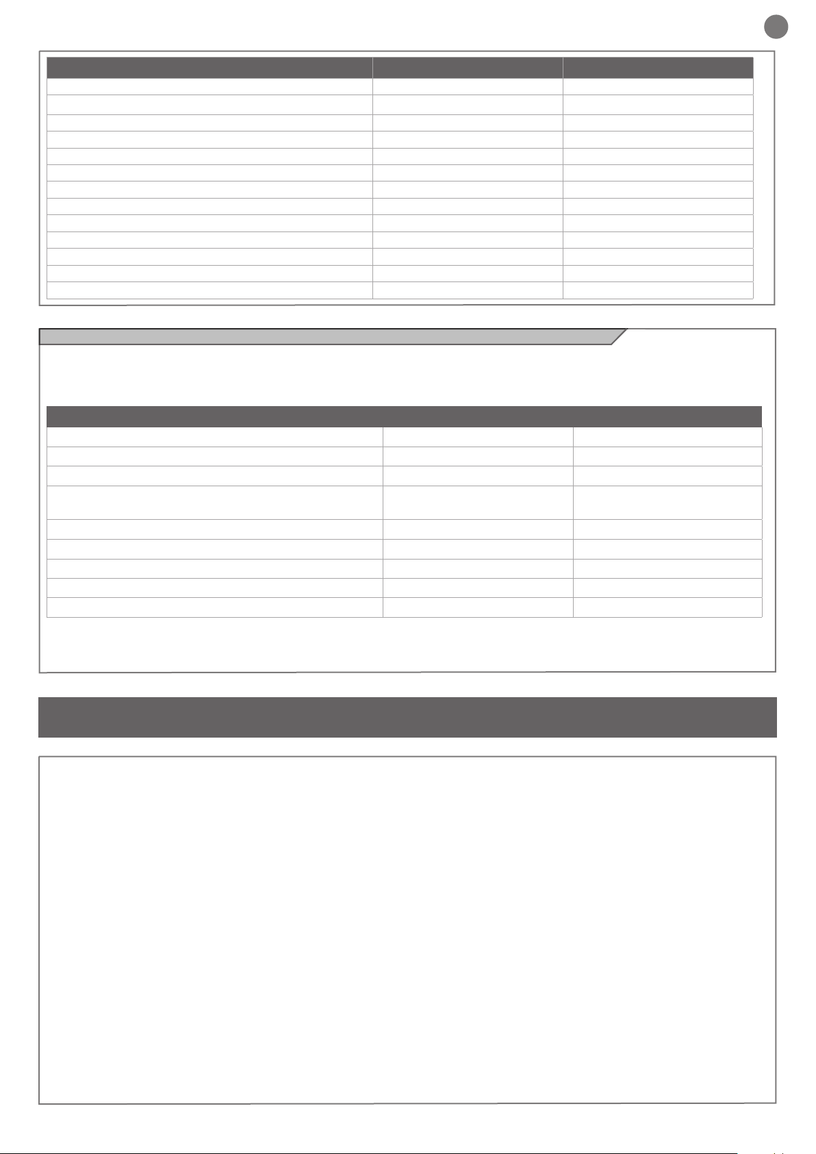
4.3 - Autolearning of the travel stroke
The rst time the control unit is powered up, an autolearning procedure must be carried out to acquire fundamental parameters such
as the travel stroke length and deceleration points.
Press the + or - keys to view not only the status of the control unit, as
explained in the rst table in point 4.2, but also the count of the opening-closing operations performed. In the operation count display,
thousands, displayed without dots, alternate with units, displayed
with dots between them (e.g.: 50.000 = 50/0.0.0).
AUTOLEARNING OF THE TRAVEL STROKE AND MAIN PARAMETERS, WITH
PRESET DECELERATIONS
The deceleration intervals are as set in the menu, with the same percentage applied during opening and
closing.
CAUTION: if manual programming of deceleration intervals is required, go to the next table
1. CAUTION! check that mechanical end stops (compulsory) are present and secure. The motors must
always reach the mechanical end stop
2. Move the gate manually to mid-travel.
3. Press the pushbuttons UP + and MENU at the same time for at least 5 seconds until LOP is displayed, then
(if necessary) press DOWN (see gure).
Ensure that motor M1 is activated rst; otherwise, press DOWN -, turn the power off and invert connections
M1 and M2. Repeat the procedure from step 3.
If the rst manoeuvre is NOT opening, press DOWN - to stop the self-learning process. Then press SS to
restart acquisition: the leaf resumes movement in the correct direction.
4. Motor M1 opens at low speed until it reaches the mechanical opening end stop.
At precisely the time of reaching the mechanical opening end stop, press the SS command.
Motor M2 starts automatically in opening mode. If motor M2 moves in closing, stop by pressing DOWN - and
resume movement using SS (the leaf resumes movement in the correct direction)
5. Motor M2 opens at low speed. At precisely the time of reaching the mechanical opening end stop,
press the SS command. After a couple of seconds, motor M2 starts automatically in closing at full speed.
UP
MENU
M1
SS
M1 M2
M2
DOWN
SS
4
5
6. Precisely when motor M2 reaches the closed position, press the SS command. Motor M2 stops and
motor M1 starts in closing.
7. Precisely when motor M1 reaches the closed position, press the SS command. Motor M1 stops and
restarts in opening.
8. Precisely when motor M1 reaches the open position, press the SS command. Motor M1 stops and
motor M2 starts in opening.
9. Precisely when motor M2 reaches the open position, press the SS command. Motor M2 stops.
20
M1
M1
SS
M1
SS
M1 M2
SS
M2
M2
M2
SS
6
7
8
9
SS
Page 21
EN
10. Motors M1 and M2 resume closing according to the leaf offset values set in the menu, i.e. the gate closes
automatically according to the set travel.
11. Run a number of opening, closing and stop manoeuvres, to check that the system is stable and there are
no assembly defects.
All main parameters are congured as default by the control unit. To
personalise installation, go to the next step in paragraph 4.4. If torque
is not sufcient to move the leaf, delete the deceleration intervals from
the menu [LSI=0].
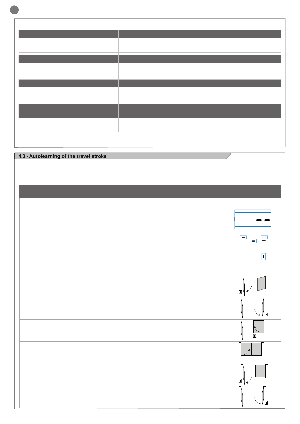
AUTOLEARNING OF THE TRAVEL STROKE AND MAIN PARAMETERS, WITH
CUSTOMISED DECELERATIONS
Deceleration intervals can be personalised by the user, according to the procedure below.
1. CAUTION! check that mechanical end stops (compulsory) are present and secure. The motors must
always reach the mechanical end stop
2. Move the gate manually to mid-travel.
3. CAUTION: enter the main menu to set the parameter LSI = p as per the table in paragraph 4.4
4. Press the pushbuttons UP + and MENU at the same time for at least 5 seconds until LOP is displayed, then
(if necessary) press DOWN (see gure).
Ensure that motor M1 opens rst; otherwise, press DOWN -, turn the power off and invert connections M1 and
M2. Repeat the procedure from step 4.
If the rst manoeuvre is NOT opening, press DOWN - to stop the self-learning process. Then press SS to
restart acquisition: the leaf resumes movement in the correct direction.
5. Motor M1 opens at low speed until it reaches the mechanical opening end stop.
At precisely the time of reaching the mechanical opening end stop, press the SS command.
Motor M2 starts automatically in opening mode. If motor M2 moves in closing, stop by pressing DOWN - and
resume movement using SS (the leaf resumes movement in the correct direction)
6. Motor M2 opens at low speed. At precisely the time of reaching the mechanical opening end stop.
After a couple of seconds, motor M2 starts automatically in closing at full speed.
M1 M2
UP
SS
M1 M2
MENU
M2
10
DOWN
SS
5M1
6
7. On reaching the point where motor M2 closing deceleration is required, press SS. M2 motor movement continues at low speed.
8. Precisely when motor M2 reaches the closed position, press the SS command. Motor M2 stops and
motor M1 starts in closing.
9. On reaching the point where motor M1 closing deceleration is required, press SS. M1 motor movement continues at low speed.
10. Precisely when motor M1 reaches the closed position, press the SS command. Motor M1 stops and
restarts in opening.
11. On reaching the point where motor M1 opening deceleration is required, press SS. M1 motor movement continues at low speed.
12. Precisely when motor M1 reaches the open position, press the SS command. Motor M1 stops and
motor M2 starts in opening.
13. On reaching the point where motor M2 opening deceleration is required, press SS. M2 motor movement continues at low speed.
SS
SS
SS
M1
M1
M1
M1
M1
M1
M1
SS
SS
M2
M2
M2
M2
M2
M2
M2
SS
10
SS
7
8
9
11
12
13
14. Precisely when motor M2 reaches the open position, press the SS command. Motor M2 stops.
15. M1 and M2 resume closing according to the offset parameter entered in the menu, i.e. the gate closes
M1 M2
M1 M2
automatically according to the set travel.
16. Run a number of opening, closing and stop manoeuvres, to check that the system is stable and there are
no assembly defects.
All main parameters are congured as default by the control unit. To personalise installation, go to the next step in paragraph 4.4.
SS
SS
14
15
21
Page 22
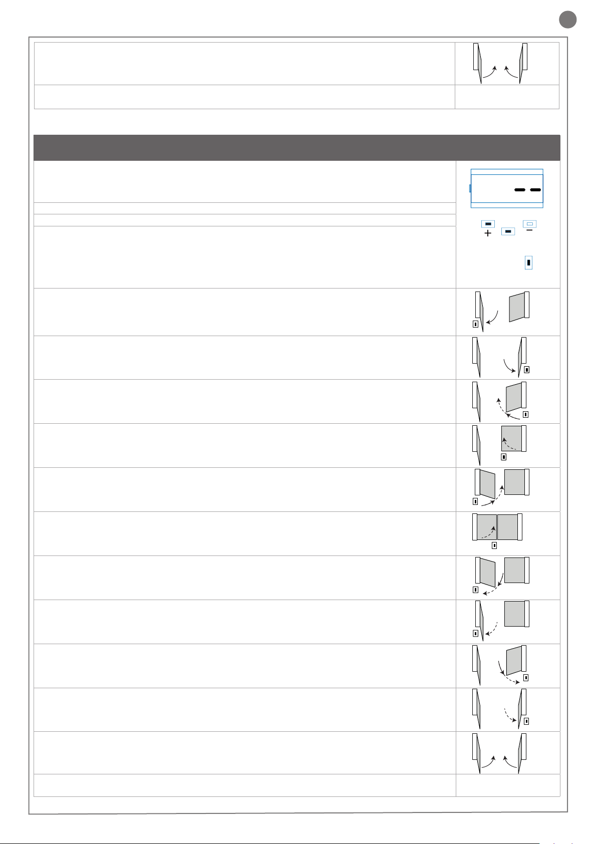
4.4 - Customising the system - BASIC MENU
n
If necessary, users may select a BASIC MENU which allows modication of the control unit’s basic parameters. To select the BASIC
MENU proceed as described below.
Exampling of modifying a BASIC MENU parameter
UP
Press the MENU key for 1 second to access the basic menu.
UP
Press the MENU key for 1 second to display the parameter
in order to save the modied
value, or MENU quickly to quit
the function without saving.
MENU
MENU
DOWN
DOWN
UP
After accessing the BASIC
MENU, press the + and – keys
to scroll through the functions.
UP
Press the + and – keys to scroll
through the functions to modify
other parameters.
DOWN
MENU
DOWN
MENU
WARNING: to be certain of accessing the NORMAL OPERATION
display state, the starting point for accessing the BASIC MENU,
press the MENU key twice
UP UP
To access the value modication function, press the MENU
key for 1 second, until the va-
lue starts to ash quickly.
UP
Press the MENU key quickly to
quit the menu.
DOWN DOWN
MENU MENU
Press the + and – keys to to
modify the value.
DOWN
MENU
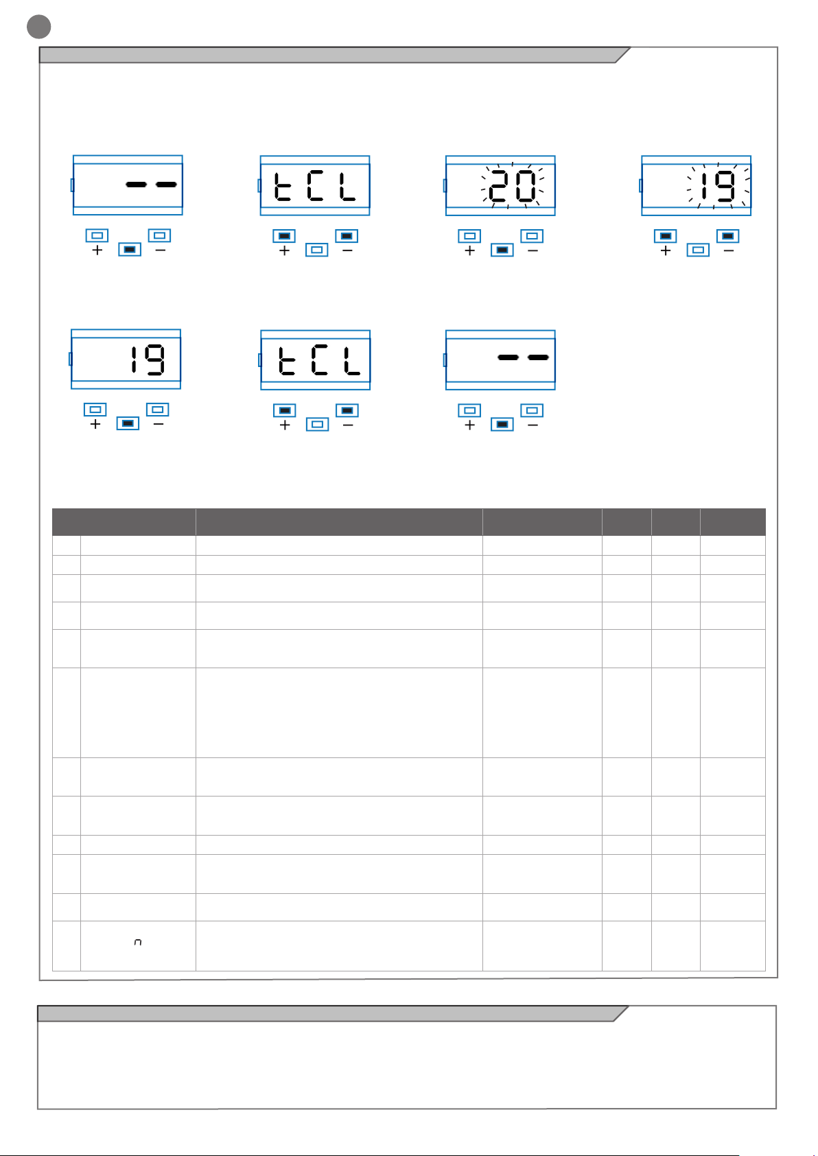
PARAMETERS DESCRIPTION
Automatic reclosing time (0 = disabled) 20 0 900 s
Reclosing after transit time (0 = disabled) 0 0 30 s
Obstacle sensitivity
(0 = disabled)
Motor force (torque at operating speed) 100 10 100
Deceleration mode
0 = deceleration 1/3 (slow)
1 = deceleration 2/3 (fast)
SS conguration:
0 = Normal (OP-ST-CL-ST-OP-ST…)
1 = Alternate STOP (OP-ST-CL-OP-ST-CL…)
2 = Alternate (OP-CL-OP-CL…)
3 = Apartment block – timer
4 = Apartment block with immediate reclosing
Response after black out
0 = no action, as per before failure
1 = Closing
Soft start (slow start-up)
0 = disabled
1 = enabled
Second leaf delay 2 0 300 s
Deceleration range
P = personalised from learning cycle
0...100% = travel percentage
Anti-slip: extension of set work time (useful in areas
subject to strong winds)
Number of motors
1 = 1 motor
2 = 2 motors
10
11
12
1
2
3
4
5
6
7
8
9
TCL
ttr
SEI
trq
SSL
SbS
bLt
SST
dLY
LSI
ASL
nMt
DEFAULT
CONFIGURATION
0 0 100
0 0 1
0 0 4
0 0 1
0 0 1
15 0 100
0 0 300 s
1 1 2
MIN MAX UNIT
% (steps
of 1)
% (steps
of 10)
% (steps
of 1)
4.5 - Connecting the radio receiver
Connect the radio receiver, removing the plastic cover and taking
care to position it as shown in the diagram in point 2.1.
For programming, follow the receiver instructions, remembering that
22EN22
the 4 outputs which can be activated are:
OUTPUT 1 = STEP BY STEP, OUTPUT 2 = PEDESTRIAN, OUTPUT 3 = OPEN, OUTPUT 4 = CLOSE.
Page 23
5 - TESTING AND COMMISSIONING THE AUTOMATION SYSTEM
The system must be tested by a qualied technician, who must
perform the tests required by the relevant standards in relation to
the risks present, to check that the installation complies with the
5.1 - Testing
All system components must be tested following the procedures described in their respective operator’s manuals;
ensure that the recommendations in Chapter 1 - Safety Warnings have been complied with;
check that the gate or door is able to move freely once the automation system has been released and is well balanced, meaning that it
will remain stationery when released in any position;
check that all connected devices (photocells, sensitive edges,
5.2 - Commissioning
Once all (and not just some) of the system devices have passed the
testing procedure, the system can be commissioned;
the system’s technical dossier must be produced and kept for 10
years. It must contain the electrical wiring diagram, a drawing or
photograph of the system, the analysis of the risks and the solutions
adopted to deal with them, the manufacturer’s declaration of conformity for all connected devices, the operator’s manual for every
device and the system maintenance plan;
relevant regulatory requirements, especially the EN12445 standard
which species the test methods for gate and door automation systems.
emergency buttons, etc.) are operating correctly by performing gate
or door opening, closing and stop tests using the connected control
devices (transmitters, buttons or switches);
perform the impact measurements as required by the EN12445
standard, adjusting the control unit’s speed, motor force and deceleration functions if the measurements do not give the required
results, until the correct setting is obtained.
draw up the declaration of conformity, the instructions and precautions for use for the end user and the system maintenance plan and
consign them to the end user;
ensure that the user has fully understood how to operate the system
in automatic, manual and emergency modes;
the end user must also be informed in writing about any risks and
hazards still present;
x a dataplate with the details of the automation, the name of the
person who commissioned it, the serial number and year of construction and the CE marking on the gate or door;
also t a sign specifying the procedure for releasing the system by
hand;
WARNING - after detecting an obstacle, the gate or door stops
during its opening travel and automatic closure is disabled; to restart operation, the user must press the control button or use the
transmitter.
23EN23
Page 24
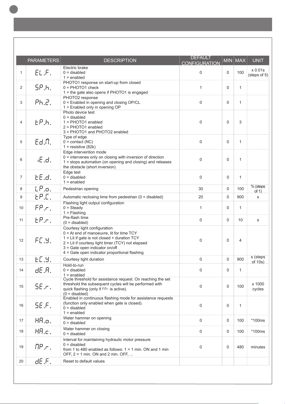
EN
PARAMETERS DESCRIPTION
DEFAULT
CONFIGURATION
MIN MAX UNIT
1
EL.F.
Electric brake
0 = disabled
1 = enabled
0 0 100
x 0.01s
(steps of 5)
2
SP.h.
PHOTO1 response on start-up from closed
0 = PHOTO1 check
1 = the gate also opens if PHOTO1 is engaged
1 0 1
3
Ph.2.
PHOTO2 response
0 = Enabled in opening and closing OP/CL
1 = Enabled only in opening OP
0 0 1
4
tP.h.
Photo device test
0 = disabled
1 = PHOTO1 enabled
2 = PHOTO1 enabled
3 = PHOTO1 and PHOTO2 enabled
0 0 3
5
ed.M.
Type of edge
0 = contact (NC)
1 = resistive (82k)
0 0 1
6
iE.D.
Edge intervention mode
0 = intervenes only on closing with inversion of direction
1 = stops automation (on opening and closing) and releases
the obstacle (short inversion)
0 0 1
7
tE.D.
Edge test
0 = disabled
1 = enabled
0 0 1
8
LP.o.
Pedestrian opening 30 0 100
% (steps
of 1)
9
TP.C.
Automatic reclosing time from pedestrian (0 = disabled) 20 0 900 s
10
FP.r.
Flashing light output conguration
0 = Steady
1 = Flashing
1 0 1
11
tP.r.
Pre-ash time
(0 = disabled)
0 0 10 s
12
FC.Y.
Courtesy light conguration
0 = At end of manoeuvre, lit for time TCY
1 = Lit if gate is not closed + duration TCY
2 = Lit if courtesy light timer (TCY) not elapsed
3 = Gate open indicator on/off
4 = Gate open indicator proportional ashing
0 0 4
13
tC.Y.
Courtesy light duration 0 0 900
s (steps
of 10s)
14
dE.A.
Hold-to-run
0 = disabled
1 = enabled
0 0 1
15
se.r.
Cycle threshold for assistance request. On reaching the set
threshold the subsequent cycles will be performed with
quick ashing (only if FPr is active).
(0 = disabled)
0 0 100
x 1000
cycles
16
se.f.
Enabled in continuous ashing mode for assistance requests
(function only enabled when gate is closed).
0 = disabled
1 = enabled
0 0 1
17
HA.o.
Water hammer on opening
0 = disabled
0 0 100 *100ms
18
HA.c.
Water hammer on closing
0 = disabled
0 0 100 *100ms
19
mp.r.
Interval for maintaining hydraulic motor pressure
0 = disabled
from 1 to 480 enabled as follows: 1 = 1 min. ON and 1 min
OFF, 2 = 1 min. ON and 2 min. OFF, ...
0 0 480 minutes
20
de.f.
Reset to default values
n
n
6 - FURTHER DETAILS - ADVANCED MENU
The ADVANCED MENU allows the system to be further customised
by modifying parameters not accessible from the basic menu
To access the ADVANCED menu, press the MENU key and hold it
To set the default values: 1) access the advanced programming
function; 2) select the “dEf” parameter”; 3) activate the modication
mode (“0” on display”); 4) accept the modication (press “MENU”
24
down for 5 seconds
To modify ADVANCED MENU parameters, proceed as described
for the BASIC MENU
and hold it down). A countdown should now appear: d80,d79...,d01
down to “don“. Release the key when nished.
Page 25

7 - INSTRUCTIONS AND WARNINGS FOR THE END USER
EN
Key Automation S.r.l. produces systems for the automation of gates,
garage doors, automatic doors, roller blinds and car-park and road
barriers. However, Key Automation is not the manufacturer of your
complete automation system, which is the outcome of the analysis,
assessment, choice of materials and installation work of your chosen installer. Every automation system is unique, and only your
installer has the experience and skill required to produce a safe,
reliable, durable system tailored to your needs, and above all that
complies with the relevant regulatory standards. Although your automation system complies with the regulation safety level, this does
not rule out the presence of “residual risk”, meaning the possibility
that hazards may occur, usually due to reckless or even incorrect
use. We would therefore like to give you some advice for the correct
use of the system:
• before using the automation system for the rst time, have the
installer explain the potential causes of residual risks to you;
• keep the manual for future reference, and pass it on to any new
owner of the automation system;
• reckless use and misuse of the automation system may make it
dangerous: do not operate the automation system with people, ani-
mal or objects within its range of action;
• a properly designed automation system has a high level of safety,
since its sensor systems prevent it from moving with people or obstacles present so that its operation is always predictable and safe.
However, as a precaution children should not be allowed to play close to the automation system, and to prevent involuntary activation,
remote controls must not be left within their reach;
• as soon as any system malfunction is noticed, disconnect the
electricity supply and perform the manual release procedure. Never
attempt repairs on your own; call in your installation engineer. In
the meantime the door or gate can be operated without automation
once the geared motor has been released using the release key
supplied with the system. In the event of safety devices out of service arrange for repairs to the automation immediately;
• Maintenance: Like any machine, your automation system needs
regular periodic maintenance to ensure its long life and total safety. Arrange a periodic maintenance schedule with your installation
engineer. Key Automation recommends that maintenance checks
should be carried out every six months for normal domestic use, but
this interval may vary depending on the level of use. Any inspection,
maintenance or repair work must only be carried out by qualied
staff.
• Never modify the automation system or its programming and setup
parameters: this is the responsibility of your installation engineer.
• Testing, routine maintenance and any repairs must be recorded by
the person who performs them and the documents must be conserved by the system’s owner.
The only procedures you are capable of, and which you are recommended to perform, are cleaning of the photocell glass and removal
of any leaves or stones that may obstruct the automation system.
To prevent anyone from activating the gate or door, release the automation system before starting. Clean only with a cloth dipped in
a little water.
At the end of its useful life, the automation system must be disman-
tled by qualied personnel, and the materials must be recycled or
disposed of in compliance with the legislation locally in force.
If after some time your remote control seems to have become less
effective, or stops operating completely, the battery may be at (depending on the level of use, this may take from several months up
to more than a year). You will realise this because the transmission
conrmation light does not come on, or only lights up for a very
short time.
Batteries contain pollutants: do not dispose of them with normal wa-
ste but follow the methods specied by the local regulations.
Thank you for choosing Key Automation S.r.l.; please visit our Inter-
net site www.keyautomation.it for further information.
• in the event of malfunctions or power failures: while waiting for the
engineer to come (or for the power to be restored if your system is
not equipped with buffer batteries), the door or gate can be used just
like any non-automated installation. To do this, the manual release
procedure must be carried out;
• manual release and operation: rst bear in mind that the release
procedure can only be carried out with the door or gate stationery.
25
Page 26

FR
TABLE DES MATIÈRES
1
Consignes de sécurité
page. 27
2
2.1
2.2
2.3
2.4
Présentation du produit
Description de la logique de commande
Description des branchements
Modèles et caractéristiques techniques
Liste des câbles nécessaires
page. 28
page. 28
page. 28
page. 28
page. 29
3
Vérications préalables
page. 29
4
4.1
4.2
4.3
4.4
4.5
Installation du produit
Branchements électriques
Visualisation en mode normal
Autoapprentissage de la course
Personnalisation de l’installation-MENU DE BASE
Branchement du récepteur radio
page. 30
page. 30
page. 31
page. 32
page. 34
page. 34
5
5.1
5.2
Réception et mise en service
Réception
Mise en service
page. 35
page. 35
page. 35
6
Approfondissements - MENU AVANCÉ
page. 36
7
Instructions et avertissements
destinés à l’utilisateur nal
page. 37
8
Déclaration CE de conformité
page. 87
26
Page 27

1 - CONSIGNES DE SÉCURITÉ
FR
ATTENTION – pour la sécurité des personnes, il est
important de respecter ces instructions et de les conserver pour pouvoir les consulter ultérieurement.
Lire attentivement les instructions avant d’effectuer l’installation.
La conception et la fabrication des dispositifs qui
composent le produit et les informations contenues
dans ce guide respectent les normes de sécurité en
vigueur. Néanmoins, une installation et une programmation erronées peuvent causer de graves blessures
aux personnes qui exécutent le travail et à celles qui
utiliseront l’installation. C’est pourquoi il est important, durant l’installation, de suivre scrupuleusement
toutes les instructions fournies dans ce guide.
Ne pas effectuer l’installation en cas de doute, de quelque nature
que ce soit, et, au besoin, demander des éclaircissements au service après-vente de Key Automation.
Pour la législation européenne, la réalisation d’une
porte ou d’un portail automatique doit respecter les
normes prévues par la directive 2006/42/CE (directive
Machines) et, en particulier, les normes EN 12445, EN
12453, EN 12635 et EN 13241-1, qui permettent de déclarer la conformité de l’automatisme.
C’est pourquoi le branchement dénitif de l’automatisme au réseau électrique, la réception de l’installation, sa mise en service et la
maintenance périodique doivent être conés à du personnel qualié
et spécialisé qui interviendra selon les instructions fournies dans la
section « Réception et mise en service de l’automatisme ».
De plus, il devra se charger de procéder aux essais prévus en fonction des risques présents et vérier le respect de toutes les prescriptions des lois, normes et règlements : en particulier, le respect
de toutes les exigences de la norme EN 12445 qui dénit les méthodes d’essai per la vérication des automatismes pour portes et
portails.
ATTENTION - Avant de commencer l’installation, effectuer les analyses et vérications suivantes:
vérier que chacun des dispositifs destinés à l’automatisme est
adapté à l’installation à réaliser. À ce sujet, contrôler tout particu-
lièrement les données indiquées dans le chapitre « Caractéristiques
techniques ». Ne pas effectuer l’installation si ne serait-ce qu’un
seul de ces dispositifs n’est pas adapté à ce type d’utilisation;
vérier que les dispositifs présents dans le kit sont sufsants pour
garantir la sécurité de l’installation et son bon fonctionnement;
effectuer l’analyse des risques, qui doit aussi comprendre la liste
des exigences essentielles de sécurité contenues dans l’annexe I
de la directive Machines, en indiquant les solutions adoptées. L’analyse des risques est l’un des documents qui constituent le dossier
technique de l’automatisme. Ce dernier doit être rédigé par un installateur professionnel.
Compte tenu des situations de risque qui peuvent se
présenter durant les phases d’installation et d’utilisation du produit, il est nécessaire d’installer l’automatisme en respectant les consignes suivantes:
Il faut faire en sorte que les pièces des composants de l’automatisme ne soient jamais plongées dans l’eau ni dans d’autres substances liquides. Durant l’installation, éviter que des liquides puissent
pénétrer à l’intérieur des dispositifs présents;
Si des substances liquides pénètrent à l’intérieur des pièces des
composants de l’automatisme, débrancher immédiatement l’alimentation électrique et s’adresser au service après-vente Key Automation. L’utilisation de l’automatisme dans ces conditions peut être
source de danger;
Ne pas mettre les différents composants de l’automatisme à pro-
ximité de sources de chaleur et ne pas les exposer à des ammes
libres. Ces actions peuvent les endommager et causer des problèmes de fonctionnement, un incendie ou des dangers;
Toutes les opérations qui nécessitent l’ouverture de la coque de
protection des différents composants de l’automatisme doivent s’effectuer avec la logique de commande débranchée de l’alimentation
électrique. Si le dispositif de mise hors tension ne peut pas être sur-
veillé, il faut poser dessus un écriteau indiquant : « MAINTENANCE
EN COURS »;
La logique de commande doit être branchée à une ligne d’alimentation électrique avec mise à la terre de sécurité;
Le produit ne peut pas être considéré comme un système de pro-
tection efcace contre l’intrusion. Si vous souhaitez vous protéger
efcacement, il faut intégrer d’autres dispositifs à l’automatisme;
Le produit ne peut être utilisé qu’après les opérations de « mise en
service » de l’automatisme, comme cela est prévu dans la section
« Réception et mise en service de l’automatisme »;
prévoir dans le réseau d’alimentation de l’installation un dispositif
de disjonction avec une distance d’ouverture des contacts qui garantisse la disjonction complète dans les conditions prévues par la
catégorie de surtension III;
Pour le raccordement de tubes rigides et exibles ou de passe-câbles, utiliser des raccords conformes à l’indice de protection IP55 ou
supérieur;
L’installation électrique en amont de l’automatisme doit être conforme aux normes en vigueur et être réalisée dans les règles de l’art;
Il est conseillé d’utiliser un bouton d’urgence à installer à proximité
de l’automatisme (raccordé à l’entrée STOP de la carte de commande) de manière à pouvoir arrêter immédiatement le portail ou la porte
en cas de danger;
Ce dispositif n’est pas destiné à être utilisé par des personnes (y
compris les enfants) dont les capacités physiques, sensorielles ou
mentales sont limitées ou qui manquent d’expérience ou de con-
naissance, à moins qu’elles aient pu bénécier, par le biais d’une
personne responsable de leur sécurité, d’une surveillance ou d’instructions relatives à l’utilisation du dispositif;
les enfants doivent être surveillés an de s’assurer qu’ils ne jouent
pas avec l’appareil.
ATTENTION - Les matériaux d’emballage de tous les
composants de l’automatisme doivent être éliminés
conformément à la norme locale en vigueur.
Ne pas apporter de modications à une quelconque partie de l’automatisme, en dehors de celles qui sont prévues dans ce guide.
Ce type d’interventions ne peut que causer des problèmes de fonctionnement. Le constructeur décline toute responsabilité en cas
de dommages dérivant de produits modiés de manière arbitraire;
ATTENTION - Les données et les informations fournies
dans ce guide peuvent être modiées par Key Automation S.r.l. à tout moment et sans obligation de préavis.
27
Page 28

FR
2 - PRÉSENTATION DU PRODUIT
2.1 - Description de la logique de commande
La logique de commande CT202 est le système de contrôle le plus
moderne et le plus efcace pour les moteurs Key Automation destinés
à l’ouverture et à la fermeture électrique de portails battants.
Toute autre utilisation impropre de la logique de commande est interdi-
te. La logique de commande CT202 est équipée d’un écran qui faci-
lite la programmation et permet de surveiller constamment l’état des
entrées ; de plus, la structure en menus simplie les paramétrages
des temps et des logiques de fonctionnement.
8
UP DOWN
9
MENU
+ -
SS
11
10
12
16
M
M
L
L1
N
1
2
1
L2
L1
L2
COURTESY L.
COM
COURTESY L.
FLASH
FLASH
24 Vac
24 Vac
EL
EL
3 4
COM
2
+24 Vdc
+ 24 TX PH
GND
14
EDGE
2.2 - Description des branchements
1- Branchements de l’alimentation 230 Vca (120 Vca)
2- Branchements des alimentations des moteurs, des condensateurs,
des clignotants et de l’éclairage automatique
3- Branchement des alimentations 24 Vcc des commandes et des
dispositifs de sécurité
4- Branchement des dispositifs de sécurité et voyants LED
ROUGES EDGE PH2-PH1-STOP
5- Branchement des commandes et voyants LED VERTS
OPEN-CLOSE-PED-SS
6- Connecteur de la carte radio embrochable RX4X (4 canaux)
7- Connecteur de l’antenne
15
6
13
7
STOP
OPEN
CLOSE
EDGE
PH2
PH1
PEDSSCOM
J4
5
6
8- Écran ACL
9- Bouton UP +
10- Bouton MENU
11- Bouton DOWN -
12- Bouton SS PAS À PAS
13- Commutateur DIP dispositifs de sécurité
14- F3- Fusible de protection des accessoires CA +
serrure électrique
2 A rapide
15- F2- Fusible de protection des accessoires CC 500 mA rapide
16- F1- Fusible de protection de la ligne 6,3 A rapide
RÉCEPTEUR RX4X
SORTIE 1 = PAS À PAS
SORTIE 2 = PIÉTON
SORTIE 3 = OUVERTURE
SORTIE 4 = LAMPES MARCHE/ARRÊT
2.3 - Modèles et caractéristiques techniques
CODE DESCRIPTION
900CT202 Logique de commande pour deux moteurs 230 V, pour portails battants
900CT202V120 Logique de commande pour deux moteurs 120 V, pour portails battants
- Alimentation protégée contre les courts-circuits à l’intérieur de la logique de commande, sur les moteurs et sur les accessoires raccordés.
- Détection des obstacles à la vitesse de régime grâce à un capteur
de courant.
28
- Apprentissage automatique des temps de fonctionnement.
- Désactivation des entrées de sécurité par commutateur DIP: il
n’est pas nécessaire de shunter les bornes relatives au dispositif de
sécurité non installé, il suft de désactiver la fonction au moyen du
commutateur DIP.
Page 29

CARACTÉRISTIQUES TECHNIQUES :
Alimentation (L-N) 230 Vac (+10% - 15%) 50-60 Hz 120 Vac (+10% - 15%) 50-60 Hz
Charge max. moteur 700 W + 700 W 700 W + 700 W
Sortie alimentation des accessoires Vdc et alimentation
24 Vdc 500 mA 24 Vdc 500 mA
pour test des dispositifs
Sortie alimentation des accessoires Vac 24 Vac 1 A 24 Vac 1 A
Sortie éclairage automatique 230 Vac 25 W 120 Vac 25 W
Sortie clignotant 230 Vac 25 W 120 Vac 25 W
Sortie serrure électrique 12 Vac / 15 VA 12 Vac / 15 VA
Temps de fonctionnement maximal avec charge nominale Réglable Réglable
Temps de pause Réglable 0-900 sec. Réglable 0-900 sec.
Température de fonctionnement -20 °C + 55 °C -20 °C + 55 °C
Fusibles ligne d’alimentation
Fusibles accessoires DC
Fusibles accessoires AC et serrure électrique
6,3AF 6,3AF
500mAF 500mAF
2AF 2AF
2.4 - Liste des câbles nécessaires
FR
Sur une installation typique, les câbles nécessaires pour les branchements des divers dispositifs sont indiqués dans le tableau des
câbles.
Les câbles utilisés doivent être adaptés au type d’installation ; par
exemple, il est conseillé d’utiliser un câble type H03VV-F pour la
pose à l’intérieur ou H07RN-F pour l’extérieur.
SPÉCIFICATIONS TECHNIQUES DES CÂBLES ÉLECTRIQUES :
Branchement câbles limite maximale admissible
Ligne électrique d’alimentation 1 x câble 3 x 1,5 mm
Ligne d’alimentation du moteur 1 x câble 4 x 1,5 mm
Clignotant, éclairage automatique
Antenne
Serrure électrique
1 x câble 4 x 0,5 mm2 **
1 x câble type RG58
1 x câble 2 x 1 mm
Photocellules émetteur 1 x câble 2 x 0,5 mm
Photocellules récepteur 1 x câble 4 x 0,5 mm
Bord sensible 1 x câble 2 x 0,5 mm
Sélecteur à clé 1 x câble 4 x 0,5 mm
2
2
20 m *
20 m
20 m
20 m (conseillé < 5 m)
2
2
2
2
2
20 m
20 m
20 m
20 m
20 m
* Si le câble d’alimentation fait plus de 30 m de long, il faut utiliser un câble d’une section supérieure (par exemple 3x2,5 mm2) et il faut
réaliser une mise à la terre de sécurité à proximité de l’automatisme.
** Deux câbles de 2 x 0.5 mm2 peuvent être utilisés à la place.
3 - VÉRIFICATIONS PRÉALABLES
Avant d’installer le produit, vérier et contrôler les points suivants:
contrôler que le portail ou la porte peuvent être automatisés;
le poids et la dimension du portail ou de la porte sur lesquels le
l’automatisme est installé doivent se situer dans les limites de fonctionnement prévues pour ce dernier;
contrôler la présence et la solidité des butées mécaniques de sécurité du portail ou de la porte;
vérier que la zone où est xé le produit n’est pas sujette aux inondations;
une atmosphère présentant une acidité ou une salinité élevée ou
la proximité de sources de chaleur pourrait causer des défaillances
dans le fonctionnement du produit;
en cas de conditions climatiques extrêmes (par exemple : neige,
gel, forte amplitude thermique, températures élevées), les frottements pourraient augmenter et donc la force requise pour l’action-
nement et le démarrage initial pourrait être supérieure à la force
nécessaire dans des conditions normales;
contrôler que l’actionnement manuel du portail ou de la porte est
uide et ne présente pas de points de frottement accru ou de risque
de déraillement;
contrôler que le portail ou la porte sont en équilibre et restent donc
arrêtés dans n’importe quelle position;
vérier que la ligne électrique à laquelle le produit est branché est
correctement mise à la terre et protégée par un disjoncteur ma-
gnétothermique différentiel;
prévoir dans le réseau d’alimentation de l’installation un dispositif
de disjonction avec une distance d’ouverture des contacts qui garantisse la disjonction complète dans les conditions prévues par la
catégorie de surtension III;
vérier que tout le matériel utilisé pour l’installation est conforme
aux normes en vigueur.
29
Page 30

FR
2
3
4
1
1
2
TX
RX
NC
PH2
2
3
4
1
1
2
TX
RX
PH1
N
L
+24 Vdc
24 Vac
24 Vac
EL
EL
GND
+ 24 TX PH
EDGE
EDGE
PH2
PH1
STOP
OPEN
CLOSE
PEDSSCOM
L
N
UP DOWN
MENU
SS
COURTESY L.
COURTESY L.
FLASH
FLASH
OUTPUT
24 Vdc
OUTPUT
24 Vac
GND_12/24
AC/DC
GND
_
12/24
AC/DC
COM
OUT
GND_12/24
AC/DC
GND
_
12/24
AC/DC
COM
OUT
NC
M
1
M
2
COM
L1
L2
COM
L1
L2
M1
M2
4 - INSTALLATION DU PRODUIT
4.1 - Branchements électriques
ATTENTION - Avant d’effectuer les branchements, vérier que la logique de commande n’est pas sous tension.
CONNECTEUR ALIMENTATIONS ET MOTEUR
L Phase alimentation 230 Vca (120 Vca) 50-60 Hz
N Neutre alimentation 230 Vca (120 Vca) 50-60 Hz
L1 Phase moteur
L2 Phase moteur
COM Commun moteur
L1 Phase moteur
L2 Phase moteur
COM Commun moteur
COURTESY L. Éclairage automatique, 230 Vca (120 Vca)
100 W, sortie également contrôlable par radio
ON-OFF (4e canal radio en sélectionnant
fC.y. = 2, tC.y. = 0)
FLASH Clignotant, 230 Vca (120 Vca) 40 W
SÉLECTEUR COMMUTATEUR DIP
Sur ON, il désactive les entrées EDGE, PH2, PH1, STOP.
Évite de devoir shunter les entrées sur le bornier.
ATTENTION - avec le commutateur DIP sur ON, les
dispositifs de sécurité raccordés sont exclus
1 = BARRE PALPEUSE
2 = PHOTO 2
3 = PHOTO 1
4 = STOP
30
Page 31

CONNECTEUR DISPOSITIFS DE SÉCURITÉ ET COMMANDES
24 Vac Alimentation des accessoires 24 Vca, 1 A
EL 12 Vac Sortie serrure électrique 12 Vca/15 VA
+24 Vdc Alimentation des accessoires positive 24 Vcc, 500 mA
GND Alimentation des accessoires négative 24 Vcc, 500 mA
+ 24 Vdc
TX PHOTO
EDGE Barre palpeuse de sécurité, ON/OFF contact NF ou résistive 8K2 entre EDGE et EDGE (attention : avec le commutateur DIP 1 sur
PH2 Photocellules (ouverture) contact NF entre PH2 et COM (attention : avec le commutateur DIP 2 sur ON, entrée de la PHOTO-
PH1 Photocellules (fermeture) contact NF entre PH1 et COM (attention : avec le commutateur DIP 3 sur ON, entrée de la PHOTO-
STOP ARRÊT de sécurité contact NF entre STOP et COM (attention : avec le commutateur DIP 4 sur ON, entrée du dispositif de
OPEN Commande D'OUVERTURE contact NO entre OPEN et COM
CLOSE Commande DE FERMETURE contact NO entre CLOSE et COM
PED Commande PIÉTON contact NO entre PED et COM
SS Commande PAS À PAS contact NO entre SS et COM
COM Commun pour les entrées PH1, PH2, STOP, OPEN, CLOSE, PED, SS
SHIELD Antenne - conducteur extérieur -
SIGNAL Antenne - signal -
Alimentation positive photocellules PH1, PH2 ; photo-test sélectionnable avec le paramètre t.p.h
ON, entrée de la BARRE PALPEUSE désactivée)
CELLULE 2 désactivée). La photocellule intervient à tout moment durant l’ouverture de l’automatisme pour bloquer immédiatement le mouvement ; l’automatisme poursuivra l’ouverture lorsque le contact sera rétabli ; durant la fermeture, la photocellule
intervient pour bloquer immédiatement le mouvement ; l’automatisme inversera le mouvement en ouverture lorsque le contact
sera rétabli.
CELLULE 1 désactivée). La photocellule intervient à tout moment durant la fermeture de l’automatisme pour bloquer immédiatement le mouvement et inverser le sens de marche ; il n’intervient pas en ouverture.
sécurité ARRÊT désactivée)
Cette entrée est considérée comme une sécurité ; le contact peut être désactivé à tout moment et arrêter immédiatement
l’automatisme en bloquant toutes les fonctions, y compris la fermeture automatique.
Contact pour la fonction de COMMANDE À ACTION MAINTENUE. Le portail S'OUVRE tant que le contact est maintenu.
Contact pour la fonction de COMMANDE À ACTION MAINTENUE. Le portail se FERME tant que le contact est maintenu.
Commande d'ouverture partielle de l'ouvrant en fonction de la sélection logicielle
Commande Ouverture/Arrêt/Fermeture/Arrêt ou en fonction de la sélection logicielle
FR
4.2 - Visualisation en mode normal
En MODE NORMAL, c’est-à-dire quand le système est mis normalement sous tension, l’écran ACL à 3 chiffres afche les messages d’état suivants:
INDICATIONS SIGNIFICATION
-OP
CL
SO
SC
HA
oP
Pe
-tC
-tP
L-LOP
LCL
Portail fermé ou remise sous tension après une mise hors tension
Portail en phase d'ouverture
Portail en phase de fermeture
Portail arrêté en phase d'ouverture
Portail arrêté en phase de fermeture
Portail arrêté par un évènement extérieur
Portail arrêté sans refermeture automatique
Portail en position d'ouverture piéton sans refermeture automatique
Portail ouvert avec refermeture temporisée
Trait clignotant : comptage en cours
Trait remplacé par un chiffre entre 0 et 9 : compte à rebours (10 dernières secondes)
Portail ouvert pour « piéton » avec refermeture temporisée
Trait clignotant : comptage en cours
Trait remplacé par un chiffre entre 0 et 9 : compte à rebours (10 dernières secondes)
Logique de commande prête pour l’apprentissage de la course
Apprentissage en phase d'ouverture
Apprentissage en phase de fermeture
31
Page 32

FR
Anomalies de fonctionnement
Ce tableau énumère certaines anomalies de fonctionnement qui peuvent se présenter.
ALARME SURCHARGE À
RÉARMEMENT MANUEL
EFO
Le courant du moteur a augmenté très rapidement
1. Le vantail a heurté un obstacle.
2. Il y a des frottements dans la rotation et le mouvement du vantail.
ALARME BARRE PALPEUSE DE
SÉCURITÉ
EED
La logique de commande a détecté un signal provenant de la barre
palpeuse de sécurité
1. Pression de la barre palpeuse de sécurité.
2. La barre palpeuse de sécurité n'est pas correctement branchée.
ALARME PHOTOCELLULES Le photo-test a donné un résultat négatif
EPH
1. Contrôler les branchements des photocellules.
2. Vérier le fonctionnement correct des photocellules.
INTERVENTION THERMIQUE ÉLECTRONIQUE Pas d'absorption de courant du moteur
Après avoir désactivé l’alarme, pour effacer tout signal d’erreur, il
suft de presser la touche « DOWN - »ou presser la commande
Eth
1. Vérier les absorptions du moteur.
2. Contrôler que la course est uide et ne rencontre pas d'obstacles.
SS (PAS À PAS)
L’écran afche de nouveau les indications normales.
4.3 - Autoapprentissage de la course
La première fois que la logique de commande est mise sous tension,
il faut exécuter une procédure d’autoapprentissage qui permette de
détecter des paramètres fondamentaux tels que la longueur de la
course et des ralentissements.
Presser les touches + ou - pour lire l’état de la logique de comman-
de, comme indiqué sur le premier tableau de la section 4.2, ainsi
que le compte des manœuvres exécutées. Durant les manœuvres,
les milliers, indiqués sans les points, et les unités, indiquées avec
des points entre chacune d’elles(exemple : 50.000 = 50/0.0.0), s’afchent alternativement.
AUTOAPPRENTISSAGE DE LA COURSE ET DES PRINCIPAUX PARAMÈTRES, AVEC
RALENTISSEMENTS PRÉÉTABLIS
Les ralentissements seront conformes aux paramètres sélectionnés dans le menu, avec le même pourcentage en phase d’ouverture qu’en phase de fermeture.
ATTENTION : si l’on souhaite aussi programmer manuellement les ralentissements, passer directement au tableau suivant.
1. ATTENTION : vérier la présence et la solidité des arrêts mécaniques, qui sont obligatoires. Les
moteurs doivent impérativement arriver jusqu’à la butée mécanique.
2. Déplacer manuellement les vantaux à mi-course.
3. Presser SIMULTANÉMENT les touches UP + et MENU pendant plus de 5 secondes jusqu’à l’afchage de
LOP et se préparer à presser (si nécessaire) la touche DOWN (voir la gure).
Vérier que le moteur M1 actionne l’ouverture le premier ; si ce n’est pas le cas, presser DOWN -, couper le
courant et inverser les branchements de M1 et M2. Répéter l’opération à partir du point 3.
Si la première manœuvre N’EST pas une ouverture, presser la touche DOWN - pour arrêter l’autoapprentissage.
Puis presser SS de manière à relancer l’autoapprentissage : le vantail reprend sa course dans le sens correct.
4. Le moteur M1 actionne l’ouverture à vitesse lente jusqu’à la butée mécanique d’ouverture.
À l’instant précis où il atteint la butée mécanique d’ouverture, envoyer une commande de SS.
Le moteur M2 actionne automatiquement l’ouverture. Si le moteur M2 se déplace en fermeture, l’arrêter avec
DOWN - et reprendre le mouvement avec SS (le vantail reprend sa course dans le sens correct).
5. Le moteur M2 actionne l’ouverture à vitesse lente. À l’instant où il atteint la butée mécanique d’ouver-
ture, envoyer une commande de SS. Au bout de deux secondes, le moteur M2 actionne automatiquement
la fermeture à vitesse normale.
6. À l’instant précis où le moteur M2 atteint la position de fermeture, envoyer une commande de SS.
Le moteur M2 s’arrête et le moteur M1 actionne la fermeture.
UP
MENU
M1
SS
M1 M2
M1
M2
M2
DOWN
SS
4
5
SS
6
7. À l’instant précis où le moteur M1 atteint la position de fermeture, envoyer une commande de SS.
Le moteur M1 s’arrête puis actionne l’ouverture.
8. À l’instant précis où le moteur M1 atteint la position d’ouverture, envoyer une commande de SS. Le
moteur M1 s’arrête et le moteur M2 actionne l’ouverture.
9. À l’instant précis où le moteur M2 atteint la position d’ouverture, envoyer une commande de SS. Le
moteur M2 s’arrête.
32
M1
SS
M1
SS
M1 M2
SS
M2
M2
7
8
9
SS
Page 33

FR
10. Le mouvement de M1 et M2 reprend en fermeture en respectant le décalage des vantaux paramétré dans
le menu : le portail se fermera donc automatiquement selon la course programmée.
11. Effectuer plusieurs manœuvres d’ouverture, de fermeture et d’arrêt soudain an de vérier que le
système est solide et qu’il ne présente aucun défaut de montage.
Tous les principaux paramètres sont congurés par défaut par la
logique de commande. Pour personnaliser l’installation, suivre les indi-
cations de la section 4.4 suivante. Si le couple n’est pas sufsant pour
actionner le vantail, éliminer les ralentissements dans le menu [LSI=0].
AUTOAPPRENTISSAGE DE LA COURSE ET DES PRINCIPAUX PARAMÈTRES, AVEC
RALENTISSEMENTS PERSONNALISÉS
Les ralentissements peuvent être personnalisés par l’utilisateur, qui devra suivre les indications ci-dessous.
1. ATTENTION : vérier la présence et la solidité des arrêts mécaniques, qui sont obligatoires. Les
moteurs doivent impérativement arriver jusqu’à la butée mécanique.
2. Déplacer manuellement les vantaux à mi-course.
3. ATTENTION : entrer dans le menu de base pour dénir le paramètre LSI = p conformément au tableau de
la section 4.4
4. Presser SIMULTANÉMENT les touches UP + et MENU pendant plus de 5 secondes jusqu’à l’afchage de
LOP et se préparer à presser (si nécessaire) la touche DOWN (voir la gure).
Vérier que le moteur M1 actionne l’ouverture le premier ; si ce n’est pas le cas, presser DOWN -, couper le
courant et inverser les branchements de M1 et M2. Répéter l’opération à partir du point 4.
Si la première manœuvre N’EST pas une ouverture, presser la touche DOWN - pour arrêter l’autoapprentis-
sage. Ensuite, presser SS de manière à lancer l’autoapprentissage : le vantail reprend sa course dans le sens
correct.
5. Le moteur M1 actionne l’ouverture à vitesse lente jusqu’à la butée mécanique d’ouverture.
À l’instant où il atteint la butée mécanique d’ouverture, envoyer une commande de SS.
Le moteur M2 actionne automatiquement l’ouverture. Si le moteur M2 se déplace en fermeture, l’arrêter avec
DOWN - et reprendre le mouvement avec SS (le vantail reprend sa course dans le sens correct).
6. Le moteur M2 actionne l’ouverture à vitesse lente. À l’instant où il atteint la butée mécanique d’ouver-
ture, envoyer une commande de SS. Au bout de deux secondes, le moteur M2 actionne automatiquement
la fermeture à vitesse normale.
7. Quand le portail a atteint le point auquel on souhaite faire commencer le ralentissement en ferme-
ture du moteur M2, envoyer une commande de SS. Le mouvement actionné par le moteur M2 continue à
vitesse lente.
8. À l’instant précis où le moteur M2 atteint la position de fermeture, envoyer une commande de SS.
Le moteur M2 s’arrête et le moteur M1 actionne la fermeture.
M1 M2
UP
SS
M1 M2
M1
M1
MENU
M2
M2
M2
DOWN
SS
SS
10
SS
5M1
6
7
8
9. Quand le portail a atteint le point auquel on souhaite faire commencer le ralentissement en ferme-
ture du moteur M1, envoyer une commande de SS. Le mouvement actionné par le moteur M1 continue à
vitesse lente.
10. À l’instant précis où le moteur M1 atteint la position de fermeture, envoyer une commande de SS.
Le moteur M1 s’arrête puis actionne l’ouverture.
11. Quand le portail a atteint le point auquel on souhaite faire commencer le ralentissement en ouver-
ture du moteur M1, envoyer une commande de SS. Le mouvement actionné par le moteur M1 continue à
vitesse lente.
12. À l’instant précis où le moteur M1 atteint la position d’ouverture, envoyer une commande de SS.
Le moteur M1 s’arrête et le moteur M2 actionne l’ouverture.
13. Quand le portail a atteint le point auquel on souhaite faire commencer le ralentissement en ouver-
ture du moteur M2, envoyer une commande de SS. Le mouvement actionné par le moteur M2 continue à
vitesse lente.
14. À l’instant précis où le moteur M2 atteint la position d’ouverture, envoyer une commande de SS.
Le moteur M2 s’arrête.
15. Le mouvement actionné par M1 et M2 reprend en fermeture en respectant le décalage des vantaux paramétré dans le menu : le portail se fermera donc automatiquement selon la course programmée.
M1
SS
M1
SS
M1
SS
M1
SS
M1
M1 M2
M1 M2
SS
M2
M2
M2
M2
M2
10
SS
SS
9
11
12
13
14
15
16. Effectuer plusieurs manœuvres d’ouverture, de fermeture et d’arrêt soudain an de vérier que le système
est solide et qu’il ne présente aucun défaut de montage.
Tous les principaux paramètres sont congurés par défaut par la logique de commande. Pour personnaliser l’installation, suivre les indications
de la section 4.4 suivante.
33
Page 34

n
4.4 - Personnalisation de l’installation - MENU DE BASE
Il est possible, au besoin, de sélectionner un MENU DE BASE qui
permet de modier les paramètres de base de la logique de commande. Pour sélectionner le MENU DE BASE, agir comme suit.
Exemple de modication d’un paramètre du MENU DE BASE
ATTENTION : pour être sûrs d’obtenir l’état de visualisation déni comme FONCTION NORMALE, point de départ qui permet
d’accéder au MENU DE BASE, presser 2 fois la touche MENU
UP
Presser la touche MENU pendant 1 seconde pour entrer
dans le menu de base.
UP
Presser la touche MENU pen-
dant 1 seconde jusqu’à l’afchage de la valeur xe pour
enregistrer mémoriser la va-
leur modiée ou bien MENU
rapidement pour sortir sans la
mémoriser.
MENU
MENU
DOWN
DOWN
UP
À l’intérieur du MENU DE
BASE, presser les touches +
et – pour faire déler les fonctions.
UP
Presser les touches + ou –
pour faire déler les fonctions,
an de modier d’autres pa-
ramètres.
PARAMETRES DESCRIPTION
Temps de la refermeture automatique (0 = désactivé) 20 0 900 s
Temps de la refermeture après le transit (0 = désactivé) 0 0 30 s
Sensibilité sur l’obstacle
(0 = désactivé)
Force moteur (couple de régime) 100 10 100
Mode ralentissement
0 = ralentissement 1/3 (lent)
1 = ralentissement 2/3 (rapide)
Conguration SS :
0 = normal (AP-ST-CH-ST-AP-ST…)
1 = alterné STOP (AP-ST-CH-AP-ST-CH…)
2 = alterné (AP-CH-AP-CH…)
3 = copropriété – temporisé
4 = copropriété avec refermeture immédiate
Comportement après une coupure de courant
0 = aucune action, conserve le même état
1 = fermeture
Soft start (démarrage ralenti)
0 = désactivé
1 = activé
Retard second vantail 2 0 300 s
Amplitude ralentissement
P = personnalisé par autoapprentissage
0…100 % = pourcentage de la course
Anti-patinage : prolonge le temps de fonctionnement
paramétré (utile dans les zones soumises à des vents forts)
Nombre de moteurs
1 = 1 moteur
2 = 2 moteurs
10
11
12
1
2
3
4
5
6
7
8
9
TCL
ttr
SEI
trq
SSL
SbS
bLt
SST
dLY
LSI
ASL
nMt
MENU
MENU
DOWN
DOWN
UP UP
Pour accéder à la modication
des valeurs, presser la touche
MENU pendant 1 seconde jusqu’à ce que la valeur clignote
rapidement.
UP
Presser la touche MENU rapidement pour sortir du menu.
DOWN DOWN
MENU MENU
DOWN
MENU
PAR
DEFAUT
0 0 100
0 0 1
0 0 4
0 0 1
0 0 1
15 0 100
0 0 300 s
1 1 2
Presser les touches + et – pour
modier la valeur.
MIN MAX UNITE
% (pas
de 1)
% (pas
de 10)
% (pas
de 1)
4.5 - Branchement du récepteur radio
Brancher le récepteur radio en retirant le couvercle en plastique et
en faisant attention à la direction, comme cela est indiqué sur la
gure, section 2.1. Pour la programmation, suivre les instructions du
34FR34
récepteur, sachant que les 4 sorties qui peuvent être activées sont :
SORTIE 1 = PAS À PAS, SORTIE 2 = PIÉTON, SORTIE 3 = OUVERTURE, SORTIE 4 = FERMETURE.
Page 35

5 - RÉCEPTION ET MISE EN SERVICE DE L’AUTOMATISME
La réception de l’installation doit être réalisée par un technicien
qualié qui doit effectuer les essais prescrits par la norme de
référence en fonction des risques présents, et vérier le respect
5.1 - Réception
Tous les composants de l’installation doivent être soumis aux essais de réception selon les procédures indiquées dans leurs guides
techniques respectifs;
contrôler que les indications de la section 1 – Consignes de sécurité
sont respectées;
contrôler que le portail ou la porte peuvent être librement actionnés
une fois que l’automatisme a été débrayé et qu’ils sont en équilibre
et restent donc en position arrêtée dans n’importe quelle position;
5.2 - Mise en service
Si la réception de tous les dispositifs de l’installation (et non pas
d’une partie) est positive, on peut effectuer la mise en service;
il faut rédiger et conserver pendant 10 ans le dossier technique
de l’installation qui devra contenir le schéma électrique, le dessin
ou la photo de l’installation, l’analyse des risques et les solutions
adoptées, la déclaration de conformité du fabricant de tous les dispositifs raccordés, le guide technique de chaque dispositif et le
plan de maintenance de l’installation;
xer sur le portail ou la porte une plaquette mentionnant les données
de l’automatisme, le nom du responsable de la mise en service, le
numéro de fabrication et l’année de construction, ainsi que la marque CE;
xer une plaquette indiquant les opérations nécessaires pour débrayer manuellement l’installation;
qu’elle est conforme aux dispositions des normes, en particulier à
celles de la norme EN12445 qui précise les méthodes d’essai à
adopter pour les automatismes pour portes et portails.
contrôler le fonctionnement correct de tous les dispositifs raccordés
(photocellules, bords sensibles, boutons d’urgence, autre) en effectuant des essais au moyen des dispositifs de commande raccordés
(émetteurs, boutons, sélecteurs);
effectuer les mesures de la force d’impact comme le prévoit la norme EN12445 en réglant les fonctions de vitesse, de force du moteur
et des ralentissements de la logique de commande, si les mesures
ne donnent pas les résultats voulus, jusqu’au paramétrage adéquat.
rédiger et remettre à l’utilisateur nal la déclaration de conformité,
les instructions et les consignes d’utilisation destinées à l’utilisateur
nal, ainsi que le plan de maintenance de l’installation;
s’assurer que l’utilisateur a correctement compris le fonctionnement
automatique, manuel et d’urgence de l’automatisme;
informer aussi l’utilisateur nal par écrit sur les dangers et les risques résiduels;
ATTENTION - après la détection d’un obstacle, le portail ou la porte s’arrête en phase d’ouverture et la fermeture automatique est
exclue ; pour que le portail reprenne sa course, il faut presser le
bouton de commande ou utiliser l’émetteur.
35FR35
Page 36

FR
n
PARAMETRES DESCRIPTION PAR DÉFAUT MIN MAX UNITÉ
1
EL.F.
Frein électrique
0 = désactivé
1 = activé
0 0 100
x 0,01 s
(pas de 5)
2
SP.h.
Comportement PHOTO1 au démarrage en position fermée
0 = Vérication PHOTO1
1 = Le portail s’ouvre même si PHOTO1 activée
1 0 1
3
Ph.2.
Comportement PHOTO2
0 = activée en ouverture comme en fermeture AP/CH
1 = activée uniquement en ouverture AP
0 0 1
4
tP.h.
Essai des dispositifs à photocellules
0 = désactivé
1 = activé PHOTO1
2 = activé PHOTO2
3 = activé PHOTO1 et PHOTO2
0 0 3
5
ed.M.
Type de barre palpeuse
0 = contact (NF)
1 = résistive (82 K)
0 0 1
6
iE.D.
Mode d’intervention barre palpeuse
0 = intervient uniquement en phase de fermeture avec inversion
du mouvement
1 = arrête l’automatisme (en ouverture comme en fermeture) et
libère l’obstacle (brève inversion)
0 0 1
7
tE.D.
Essai barre palpeuse
0 = désactivé
1 = activé
0 0 1
8
LP.o.
Porte piétonne 30 0 100 % (pas de 1)
9
TP.C.
Temps de refermeture automatique après ouverture piéton (0 =
désactivé)
20 0 900 s
10
FP.r.
Conguration sortie clignotant
0 = xe
1 = clignotant
1 0 1
11
tP.r.
Temps de pré-clignotement
(0 = désactivé)
0 0 10 s
12
FC.Y.
Conguration éclairage automatique
0 = à la n de la manœuvre, allumé pendant le temps TCY
1 = allumé si le portail n’est pas fermé + temps TCY
2 = allumé tant que le temporisateur de l’éclairage automatique
(TCY) n’est pas à la n
3 = voyant portail ouvert on/off
4 = voyant portail ouvert à clignotement proportionnel
0 0 4
13
tC.Y.
Durée éclairage automatique 0 0 900
s (pas de
10 s)
14
dE.A.
Commande à action maintenue
0 = désactivée
1 = activée
0 0 1
15
se.r.
Seuil cycles demande d’assistance. Le seuil paramétré
a été atteint, les cycles suivants seront effectués avec
un clignotement rapide (uniquement si FPr est actif).
(0 = désactivé)
0 0 100
x 1000
cycles
16
se.f.
Activation du clignotement continu pour demande d’assistance
(fonction exécutée uniquement si le portail est fermé).
0 = désactivée
1 = activée
0 0 1
17
HA.o.
Coup de bélier en ouverture
0 = désactivé
0 0 100 *100ms
18
HA.c.
Coup de bélier en fermeture
0 = désactivé
0 0 100 *100ms
19
mp.r.
Intervalle de maintien de la pression des moteurs hydrauliques
0 = désactivé
de 1 à 480 activé comme suit : 1 = 1 min ON et 1 min OFF, 2 = 1
min ON et 2 min OFF, ...
0 0 480 minutes
20
de.f.
Rétablissement des valeurs par défaut
n
6 - APPROFONDISSEMENTS- MENU AVANCÉ
Le MENU AVANCÉ permet de personnaliser encore l’installation en
modiant des paramètres qui ne sont pas accessibles à l’intérieur
du menu de base.
Pour accéder au menu AVANCÉ, presser pendant 5 secondes la
touche MENU
Pour modier les paramètres du MENU AVANCÉ, suivre les indications fournies pour le MENU DE BASE
Pour rétablir les valeurs par défaut : 1) entrer dans la programmation avancée ; 2) sélectionner le paramètre dEf ; 3) activer le mode
modication (0 s’afche) ; 4) accepter la modication (presser
36
MENU sans relâcher). On doit alors visualiser un compte à rebours
d80,d79...,d01 jusqu’à « don ». On peut alors relâcher la touche.
Page 37

7 - INSTRUCTIONS ET CONSIGNES DESTINÉES À L’UTILISATEUR FINAL
FR
Key Automation S.r.l. produit des automatismes pour portails, portes de garage, portes automatiques, rideaux métalliques, barrières
pour parkings et barrières routières. Toutefois, c’est de votre installateur de conance que dépendra votre automatisme, qui sera
installé chez vous par ses soins, après un travail méticuleux d’analyse, d’évaluation et de choix du matériel. Chaque automatisme
est unique et seul votre installateur possède l’expérience et le professionnalisme requis pour exécuter une installation conforme à vos
exigences, sûre et able dans la durée, et surtout dans les règles de
l’art et en conformité avec les normes en vigueur. Même si l’automatisme en votre satisfait le niveau de sécurité requis par les normes,
cela n’exclut pas la présence d’un « risque résiduel », à savoir la
possibilité que puissent survenir des dangers, généralement dus
à une utilisation négligente voire incorrecte ; c’est pourquoi nous
tenons à vous fournir quelques conseils sur les comportements à
suivre:
• avant d’utiliser pour la première fois l’automatisme, demandez à
l’installateur de vous expliquer l’origine des risques résiduels;
• conservez le guide pour pouvoir le consulter ultérieurement en
cas de doute et remettez-le à l’ éventuel nouveau propriétaire de
l’automatisme;
• une utilisation négligente et impropre de l’automatisme peut le rendre dangereux : n’actionnez pas le mouvement de l’automatisme si
des personnes, des animaux ou des objets se trouvent dans son
rayon d’action.
• si elle a été adéquatement conçue, l’installation d’un automatisme garantit un niveau de sécurité élevé, empêche, grâce à ses
systèmes de détection, tout mouvement en présence de personnes
ou d’objets et garantit une activation toujours prévisible et sûre. Il
est toutefois prudent d’interdire aux enfants de jouer à proximité de
l’automatisme et, pour éviter tout risque d’activation involontaire, de
ne jamais laisser les émetteurs à leur portée;
• dès que vous remarquez un quelconque comportement anomal
de l’automatisme, mettez l’installation hors tension et effectuez le
débrayage manuel. N’essayez pas de réparer vous-même l’automatisme : demandez l’intervention de votre installateur de conance : en attendant, l’installation peut fonctionner comme une ouverture non automatisée, une fois que l’opérateur a été débrayé au
moyen d’une clé de débrayage fournie avec l’installation. Avec les
dispositifs de sécurité hors d’usage, il est nécessaire de faire réparer l’automatisme au plus vite;
• Maintenance : comme toute machine, votre automatisme a besoin d’une maintenance périodique pour pouvoir fonctionner le
plus longtemps possible et en toute sécurité. Dénissez avec votre
installateur un plan de maintenance périodique ; Key Automation
conseille une intervention tous les 6 mois pour une utilisation domestique normale, sachant que cette période peut varier en fonction
de l’intensité d’utilisation. Toutes les interventions de contrôle, de
maintenance ou de réparation doivent être conées exclusivement
à du personnel qualié.
• Ne modiez pas l’installation et les paramètres de programmation
et de réglage de l’automatisme : la responsabilité en incombe à
votre installateur.
• La réception, les opérations de maintenance périodiques et les
éventuelles réparations doivent faire l’objet d’un rapport rédigé par
les techniciens concernés et lesdits documents doivent conservés
par propriétaire de l’installation.
Les seules interventions que vous êtes autorisé à effectuer et que
nous vous conseillons d’exécuter périodiquement sont : le nettoyage des vitres des photocellules et l’élimination des feuilles ou des
cailloux qui pourraient gêner le fonctionnement de l’automatisme.
Pour empêcher que quiconque puisse actionner le portail ou la porte, avant de commencer, n’oubliez pas de débrayer l’automatisme
et d’utiliser pour le nettoyage un simple chiffon légèrement imbibé
d’eau.
Á la n de la vie de l’automatisme, assurez-vous que le démantèlement est effectué par du personnel qualié et que les matériaux sont
recyclés ou éliminés conformément aux normes locales en vigueur.
Si, au bout d’un certain temps, votre radiocommande semble moins
bien fonctionner ou ne plus fonctionner du tout, cela peut être dû
simplement au fait que la pile est épuisée (selon l’utilisation, entre
quelques mois et un an). C’est le cas, notamment, si le voyant de
conrmation de la transmission ne s’allume pas ou s’il ne s’allume
qu’un bref instant.
Les piles contiennent des substances polluantes : ne les jetez pas
dans les déchets normaux et respectez les méthodes prévues par
les règlements locaux.
Nous vous remercions d’avoir choisi Key Automation S.r.l et vous
invitons à visiter notre site Internet www.keyautomation.it pour plus
d’informations.
• en cas de rupture ou de coupure de courant: en attendant l’intervention de votre installateur ou le rétablissement du courant si
l’installation n’est pas équipée de batteries tampon, l’automatisme
peut être actionné comme n’importe quelle ouverture non automatisée. Pour ce faire, il faut effectuer le débrayage manuel;
• débrayage et mouvement manuel : avant d’effectuer cette opération, ne pas oublier que le débrayage ne peut se faire qu’avec
l’ouvrant arrêté.
37
Page 38

ES
ÍNDICE
1
Advertencias para la seguridad
pag. 39
2
2.1
2.2
2.3
2.4
Introducción al producto
Descripción de la central
Descripción de las conexiones
Modelos y características técnicas
Lista de los cables necesarios
pag. 40
pag. 40
pag. 40
pag. 40
pag. 41
3
Controles preliminares
pag. 41
4
4.1
4.2
4.3
4.4
4.5
Instalación del producto
Conexiones eléctricas
Visualización modo normal
Autoaprendizaje de la carrera
Personalización del sistema - MENÚ BÁSICO
Conexión del receptor
pag. 42
pag. 42
pag. 43
pag. 44
pag. 46
pag.46
5
5.1
5.2
Ensayo y puesta en servicio
Ensayo
Puesta en servicio
pag. 47
pag. 47
pag. 47
6
Descripción detallada - MENÚ AVANZADO
pag. 48
7
Instrucciones y advertencias
destinadas al usuario nal
pag. 49
8
Declaración de conformidad CE
pag. 87
38
Page 39

1 - ADVERTENCIAS PARA LA SEGURIDAD
ES
ATENCIÓN – INSTRUCCIONES ORIGINALES – instrucciones
importantes de seguridad. Para la seguridad de las personas
es importante respetar las siguientes instrucciones de seguridad. Guarde estas instrucciones.
Lea detenidamente las instrucciones antes de realizar la instalación.
El diseño y la fabricación de los dispositivos que componen
el producto y las informaciones contenidas en este manual
respetan las normativas vigentes sobre la seguridad. No obstante esto, una instalación y una programación incorrectas
pueden provocar graves lesiones a las personas que realizan
el trabajo y a aquellas que utilizarán el sistema. Por dicho motivo, durante la instalación es importante respetar escrupulosamente todas las instrucciones mencionadas en este manual.
No proceda con la instalación si tuviera alguna duda y, si fuera necesario, solicite aclaraciones al Servicio de Asistencia Key Automation.
Para la legislación Europea la realización de una puerta automática debe respetar las Normas previstas por la Directiva
2006/42/CE (Directiva de Máquinas) y, en particular, las Normas
EN 12445, EN 12453, EN 12635 y EN 13241-1, que permiten declarar la conformidad del automatismo.
En virtud de esto, la conexión denitiva del automatismo a la red
eléctrica, el ensayo del sistema, su puesta en servicio y el man-
tenimiento periódico deben ser realizados por personal calicado
y experto, respetando las instrucciones indicadas en el apartado
“Ensayo y puesta en servicio del automatismo”.
Además, el personal deberá establecer los ensayos previstos en
función de los riesgos presentes y deberá comprobar la conformidad con las leyes, normativas y reglamentos: en particular, el respeto de todos los requerimientos de la Norma EN 12445 que establece los métodos de ensayo para las puertas motorizadas.
ATENCIÓN - Antes de comenzar con la instalación, realice los
siguientes análisis y controles:
compruebe que los dispositivos destinados al automatismo sean
adecuados para el sistema que se debe realizar. Para tal n, controle detenidamente los datos indicados en el capítulo “Características
técnicas”. No realice la instalación incluso si uno de dichos dispositivos no es adecuado para el uso;
si el cable de alimentación estuviera dañado, deberá ser sustituido
por el fabricante o por su servicio de asistencia técnica, o bien por
una persona cualicada con el n de prevenir cualquier tipo de riesgo;
si sustancias líquidas penetraran en el interior de las piezas de los
componentes del automatismo, desconecte inmediatamente la alimentación eléctrica y contacte con el Servicio de Asistencia Key
Automation. Utilizar el automatismo en dichas condiciones podría
causar situaciones peligrosas.
No coloque los componentes del automatismo cerca de fuentes de
calor ni los exponga al fuego. Esto podría averiarlos y provocar fallos de funcionamiento, incendios o situaciones peligrosas;
todas las operaciones que requieren la apertura de la cubierta de
protección de los componentes del automatismo deben hacerse
con la central desconectada de la alimentación eléctrica. Si el dispositivo de desconexión no estuviera a la vista, cuelgue un cartel
que indique: “MANTENIMIENTO EN CURSO”;
todos los dispositivos deben estar conectados a una línea de alimentación eléctrica con puesta a tierra de seguridad incorporada;
el producto no puede ser considerado un sistema de protección ecaz contra las intrusiones. Si usted deseara una protección ecaz,
es necesario integrar el automatismo con otros dispositivos;
el producto se puede utilizar exclusivamente después de haber realizado la “puesta en servicio” del automatismo, tal como previsto en
el apartado “Ensayo y puesta en servicio del automatismo”;
instale en la red de alimentación del sistema un dispositivo de desconexión con una distancia de apertura de los contactos que permita la desconexión completa en las condiciones establecidas por
la categoría de sobretensión III;
para la conexión de tubos rígidos o exibles o prensaestopas, utilice
racores de conformidad con el grado de protección IP55 o superior;
el sistema eléctrico que alimenta el automatismo debe responder a
las normativas vigentes y debe estar realizado correctamente;
se aconseja instalar un pulsador de emergencia cerca del automatismo (conectado a la entrada STOP de la tarjeta de mando) para
que sea posible detener inmediatamente la puerta en caso de peligro;
compruebe que los dispositivos comprados sean sucientes para
garantizar la seguridad del sistema y su funcionamiento;
realice el análisis de los riesgos que debe incluir la lista de los requerimientos esenciales de seguridad indicados en el Anexo I de la
Directiva de Máquinas, indicando las soluciones tomadas. El análisis de los riesgos es uno de los documentos que constituyen el
expediente técnico del automatismo. El mismo deberá ser cumplimentado por un instalador profesional.
Teniendo en cuenta las situaciones peligrosas que pueden generarse durante las etapas de instalación y uso del producto,
es necesario instalar el automatismo respetando las siguientes
advertencias:
no modique ninguna pieza del automatismo, salvo aquellas previstas en este manual. Las operaciones de este tipo pueden provocar
solo fallos en el funcionamiento. El fabricante no se asume ninguna
responsabilidad por los daños provocados por los productos modi-
cados arbitrariamente;
procure que las piezas de los componentes del automatismo no
queden sumergidas en agua o en otras sustancias líquidas. Durante la instalación, evite que los líquidos puedan penetrar en el interior
de los dispositivos;
este dispositivo no está destinado para ser utilizado por personas
(incluidos los niños) de reducidas capacidades físicas, sensoriales
o mentales, o sin experiencia y sin conocimientos, salvo que una
persona responsable de su seguridad las haya instruido sobre el
uso del dispositivo;
antes de poner en marcha el automatismo, asegúrese de que no
haya ninguna persona en las cercanías;
antes de limpiar o mantener el automatismo, desconecte la corriente eléctrica;
tenga mucho cuidado para evitar el aplastamiento entre la parte
guiada y los elementos jos de alrededor;
controle que los niños no jueguen con el dispositivo.
ATENCIÓN - elimine el material de embalaje de todos los componentes del automatismo respetando la normativa vigente del
país de instalación.
ATENCIÓN - Los datos e informaciones indicados en este manual pueden ser modicados en cualquier momento y sin la
obligación de preaviso por parte de Key Automation S.r.l.
39
Page 40

ES
2 - INTRODUCCIÓN AL PRODUCTO
2.1 - Descripción de la central
La central CT202 es el sistema de control más moderno y eciente
de los motores Key Automation para la pertura y el cierre eléctrico de
puertas de batiente.
Cualquier otro uso de la central será considerado inadecuado. La cen-
tral CT202 incorpora una pantalla que permite programar fácilmente
y monitorizar de manera constante las entradas; además, la estruc-
tura de menú permite congurar de manera sencilla los tiempos de
trabajo y las lógicas de funcionamiento.
8
UP DOWN
9
MENU
+ -
SS
11
10
12
16
M
M
L
L1
N
1
2
1
L2
L1
L2
COURTESY L.
COM
COURTESY L.
FLASH
FLASH
24 Vac
24 Vac
EL
EL
3 4
COM
2
+24 Vdc
+ 24 TX PH
GND
14
EDGE
EDGE
PH2
2.2 - Descripción de las conexiones
1- Conexiones de alimentación 230 Vca (120 Vca)
2- Conexiones de alimentaciones de los motores/condensadores/luces
intermitentes y luz de cortesía
3- Conexión de alimentaciones 24 Vcc/Vca de los mandos y dispositivos
de seguridad
4- Conexión de los dispositivos de seguridad e indicaciones LED ROJOS
EDGE PH2-PH1-STOP
5- Conexión de los mandos e indicaciones LED VERDES OPEN-CLOSE-
PED-SS
6- Conector de la tarjeta radio enchufable RX4X (4 canales)
7- Conector de la antena
15
6
13
7
STOP
OPEN
CLOSE
PH1
PEDSSCOM
J4
5
6
8- Pantalla LCD
9- Pulsador UP +
10- Pulsador MENU
11- Pulsador DOWN 12- Pulsador SS PASO A PASO
13- Dip switch dispositivos de seguridad
14- F3- Fusible de protección de los accesorios AC + electrocerradura
2 A rápido
15- F2- Fusible de protección de los accesorios DC 500 mA rápido
16- F1- Fusible de protección de la línea 6,3 A rápido
RECEPTOR RX4X
SALIDA 1 = PASO A PASO
SALIDA 2 = PASO DE PEATONES
SALIDA 3 = ABRIR
SALIDA 4 = LUCES ON/OFF
2.3 - Modelos y características técnicas
CÓDIGO DESCRIPCIÓN
900CT202 Central para dos motores de 230V, para puertas de batiente
900CT202V120 Central para dos motores de 120V, para puertas de batiente
- Alimentación protegida contra los cortocircuitos en el interior de la
central, en los motores y en los accesorios conectados.
- Detección de los obstáculos durante la velocidad de funcionamiento mediante sensor de corriente.
40
- Aprendizaje automático de los tiempos de funcionamiento.
- Desactivación de las entradas de seguridad mediante dip switch:
no es necesario puentear los bornes relativos al dispositivo de segu-
ridad no instalado, es suciente inhabilitar la función de dip switch.
Page 41

CARACTERÍSTICAS TÉCNICAS:
Alimentación (L-N) 230 Vac (+10% - 15%) 50-60 Hz 120 Vac (+10% - 15%) 50-60 Hz
Carga máx. del motor 700 W + 700 W 700 W + 700 W
Salida de alimentación de los accesorios Vdc y
24 Vdc 500 mA 24 Vdc 500 mA
alimentación test dispositivos
Salida de alimentación de los accesorios Vac 24 Vac 1 A 24 Vac 1 A
Salida luz de cortesía 230 Vac 25 W 120 Vac 25 W
Salida luz intermitente 230 Vac 25 W 120 Vac 25 W
Salida de la electrocerradura 12 Vac / 15 VA 12 Vac / 15 VA
Tiempo máximo de funcionamiento con carga nominal Regulable Regulable
Tiempo de pausa Regulable 0-900 sec. Regulable 0-900 sec.
Temperatura de funcionamiento -20 °C + 55 °C -20 °C + 55 °C
Fusibles línea de alimentación
Fusibles accesorios DC
Fusibles accesorios AC y electrocerradura
6,3AF 6,3AF
500mAF 500mAF
2AF 2AF
2.4 - Lista de los cables necesarios
En el sistema típico los cables necesarios para las conexiones de los
distintos dispositivos están indicados en la tabla lista de los cables.
Los cables utilizados deben ser adecuados para el tipo de instala-
ción; por ejemplo, se aconseja un cable H03VV-F para interiores o
H07RN-F para exteriores.
ESPECIFICACIONES TÉCNICAS DE LOS CABLES ELÉCTRICOS:
Conexión cable límite máximo permitido
Línea eléctrica de alimentación 1 x cable 3 x 1,5 mm
Línea alimentación motor 1 x cable 4 x 1,5 mm
Luz intermitente, courtesy light
Antena
Electrocerradura
1 x cable 4 x 0,5 mm2 **
1 x cable tipo RG58
1 x cable 2 x 1 mm
Fotocélulas transmisor 1 x cable 2 x 0,5 mm
Fotocélulas receptor 1 x cable 4 x 0,5 mm
Banda sensible 1 x cable 2 x 0,5 mm
Selector de llave 1 x cable 4 x 0,5 mm
2
2
20 m *
20 m
20 m
20 m (aconsejado < 5 m)
2
2
2
2
2
20 m
20 m
20 m
20 m
20 m
* Si el cable de alimentación midiera más de 30 m, tendrá que utilizar un cable de sección más grande (3x2,5 mm2) y habrá que instalar una
puesta a tierra de seguridad cerca de la automation.
** Como alternativa se pueden utilizar dos cables 2 x 0,5 mm2
3 - CONTROLES PRELIMINARES
Antes de instalar el producto, compruebe y controle los siguientes
puntos:
controle que la puerta sea adecuada para ser automatizada;
el peso y las medidas de la puerta deben estar dentro de los lími-
tes de uso especicados para el automatismo donde se instala el
producto;
controle la presencia y solidez de los topes mecánicos de seguridad
de la puerta;
compruebe que la zona de jación del producto no se inunde;
las condiciones de alta acidez o salinidad o la proximidad a fuentes
de calor pueden causar fallos de funcionamiento en el producto;
en caso de condiciones climáticas extremas (por ejemplo nieve,
helada, excursión térmica elevada, altas temperaturas) podrían
aumentar las fricciones y, por lo tanto, la fuerza necesaria para el
movimiento y el punto de arranque inicial podrían ser superiores a
los necesarios en condiciones normales;
controle que el movimiento manual de la puerta sea uido y no tenga zonas de fricción y que no exista el riesgo de descarrilamiento
de la misma;
controle que la puerta esté equilibrada y que no se mueva de la
posición en que se la deja;
compruebe que la línea eléctrica a la que se deba conectar el producto tenga una puesta a tierra de seguridad y esté protegida por
un dispositivo magnetotérmico y diferencial;
instale en la red de alimentación del sistema un dispositivo de desconexión con una distancia de apertura de los contactos que permita la desconexión completa en las condiciones establecidas por
la categoría de sobretensión III;
compruebe que todo el material utilizado para la instalación sea
conforme a las normativas vigentes.
41ES41
Page 42

ES
2
3
4
1
1
2
TX
RX
NC
PH2
2
3
4
1
1
2
TX
RX
PH1
N
L
+24 Vdc
24 Vac
24 Vac
EL
EL
GND
+ 24 TX PH
EDGE
EDGE
PH2
PH1
STOP
OPEN
CLOSE
PEDSSCOM
L
N
UP DOWN
MENU
SS
COURTESY L.
COURTESY L.
FLASH
FLASH
OUTPUT
24 Vdc
OUTPUT
24 Vac
GND_12/24
AC/DC
GND
_
12/24
AC/DC
COM
OUT
GND_12/24
AC/DC
GND
_
12/24
AC/DC
COM
OUT
NC
M
1
M
2
COM
L1
L2
COM
L1
L2
M1
M2
4 - INSTALACIÓN DEL PRODUCTO
4.1 - Conexiones eléctricas
ATENCIÓN - Antes de realizar las conexiones, compruebe que la central no esté alimentada
CONECTOR ALIMENTACIONES Y MOTOR
L Fase alimentación 230 Vca (120 Vca) 50-60 Hz
N Neutro alimentación 230 Vca (120 Vca) 50-60 Hz
L1 Fase motor
L2 Fase motor
COM Común motor
L1 Fase motor
L2 Fase motor
COM Común motor
COURTESY L. Luz de cortesía, 230 Vca (120 Vca) 100 W, sa-
lida controlable también por radio ON-OFF (4°
canal radio seleccionando fC.y. = 2, tC.y. = 0)
FLASH Luz intermitente, 230 Vca (120 Vca) 40 W
SELECTOR DIP SWITCH
Ajustado en “ON” inhabilita las entradas EDGE, PH2, PH1, STOP.
Elimina la necesidad de puentear las entradas en la regleta.
ATENCIÓN - con el dip switch en ON, los dispositi-
vos de seguridad conectados quedan desactivados
1 = BANDA
2 = FOTOCÉLULA 2
3 = FOTOCÉLULA 1
4 = STOP
42
Page 43

CONECTOR DISPOSITIVOS DE SEGURIDAD Y MANDOS
24 Vac Alimentación de los accesorios 24 Vca, 1 A
EL 12 Vac Salida electrocerradura 12 Vca / 15 VA
+24 Vdc Alimentación positiva de los accesorios 24 Vcc, 500 mA
GND Alimentación negativa de los accesorios 24 Vcc, 500 mA
+ 24 Vdc
TX PHOTO
EDGE Banda de seguridad, ON/OFF contacto NC o resistivo 8K2 entre EDGE y EDGE (atención, el dip switch 1 en ON inhabilita la entra-
PH2 Fotocélulas (apertura) contacto NC entre PH2 y COM (atención, el dip switch 2 en ON inhabilita la entrada del dispositivo de
PH1 Fotocélulas (cierre) contacto NC entre PH1 y COM (atención, el dip switch 3 en ON inhabilita la entrada del dispositivo de
STOP STOP seguridad contacto NC entre STOP y COM (atención, el dip switch 4 en ON inhabilita la entrada de seguridad STOP)
OPEN Mando APERTURA contacto NA entre OPEN y COM
CLOSE Mando CIERRE contacto NA entre CLOSE y COM
PED Mando PASO DE PEATONES contacto NA entre PED y COM
SS Mando PASO A PASO contacto NA entre SS y COM
COM Común para las entradas PH1, PH2, STOP, OPEN, CLOSE, PED, SS
SHIELD Antena - trenza -
SIGNAL Antena - señal -
Alimentación positiva de las fotocélulas PH1, PH2; fototest seleccionable con parámetro t.p.h
da del dispositivo de seguridad BANDA)
seguridad FOTOCÉLULA 2). La fotocélula se activa en cualquier momento durante la apertura del automatismo, bloqueando
inmediatamente el movimiento, el automatismo seguirá abriéndose al restablecerse el contacto; durante el cierre la fotocélula
se activa bloqueando inmediatamente el movimiento, el automatismo invierte el movimiento durante la apertura al restablecerse el contacto.
seguridad FOTOCÉLULA 1). La fotocélula se activa en cualquier momento durante el cierre del automatismo, bloqueando
inmediatamente el movimiento e invirtiendo el sentido de funcionamiento; durante la apertura no se activa.
Dicha entrada es considerada una seguridad; el contacto puede desactivarse en cualquier momento bloqueando inmediatamente el automatismo, inhabilitando cualquier función, incluido el Cierre Automático
Contacto para la función HOMBRE PRESENTE. La puerta se ABRE mientras se pulsa el contacto
Contacto para la función HOMBRE PRESENTE. La puerta se CIERRA mientras se pulsa el contacto
Mando de apertura parcial de la hoja de acuerdo con la selección software
Mando Abrir/Stop/Cerrar/Stop o de acuerdo con la selección software
4.2 - Visualización modo normal
En “MODO NORMAL”, es decir cuando normalmente se activa la alimentación al sistema, la pantalla LCD de 3 cifras muestra los siguientes mensajes de estado:
INDICACIONES SIGNIFICADO
-OP
CL
SO
SC
HA
oP
Pe
-tC
-tP
L-LOP
LCL
Puerta cerrada o reencendido después del apagado
Puerta abriéndose
Puerta cerrándose
Puerta detenida en la apertura
Puerta detenida en el cierre
Puerta detenida por acontecimiento exterior
Puerta detenida sin cierre automático
Puerta en posición de apertura paso de peatones sin cierre automático
Puerta abierta con cierre temporizado
Guión intermitente conteo en curso
Guión sustituido por cifra 0..9 conteo regresivo (últimos 10 s)
Puerta abierta paso de peatones con cierre temporizado
Guión intermitente conteo en curso
Guión sustituido por cifra 0..9 conteo regresivo (últimos 10 s)
Central lista para el aprendizaje de la carrera
Aprendizaje durante apertura
Aprendizaje durante cierre
43ES43
Page 44

Irregularidades de funcionamiento
En este apartado se mencionan algunas anomalías de funcionamiento que se pueden producir.
ALARMA SOBRECARGA IMPULSIVA La corriente del motor aumenta muy rápido
EFO
1. La hoja ha golpeado un obstáculo.
2. Se producen fricciones en el deslizamiento de la hoja.
ALARMA BANDA DE SEGURIDAD La central ha detectado una señal de la banda de seguridad
EED
1. La banda de seguridad está presionada.
2. La banda de seguridad no está conectada correctamente.
ALARMA FOTOCÉLULAS El fototest ha dado un resultado negativo
EPH
1. Controle las conexiones de las fotocélulas.
2. Compruebe el funcionamiento correcto de las fotocélulas.
ACTIVACIÓN TÉRMICO ELECTRÓNICO El motor no absorbe corriente
Eth
Tras haber solucionado la condición de alarma, para cancelar cualquier señal de error es suciente presionar el pulsador
1. Controle las absorciones del motor.
2. Controle que la carrera sea uida y libre de obstáculos.
“DOWN -” o bien presionar el mando SS (PASO A PASO)
La pantalla restablece las indicaciones normales.
4.3 - Autoaprendizaje de la carrera
La primera vez que se alimenta la central debe realizarse un pro-
cedimiento de autoaprendizaje que permita detectar los parámetros
fundamentales como la longitud de la carrera y las ralentizaciones.
Presionando los pulsadores + o - se puede leer el estado de la
central, como descrito en la primera tabla del apartado 4.2, y el
conteo de los movimientos realizados. En la visualización de los
movimientos se alternan los miles, indicados sin puntos, y las uni-
dades, indicadas con puntos entre sí (ejemplo: 50.000 = 50/0.0.0).
AUTOAPRENDIZAJE DE LA CARRERA Y DE LOS PARÁMETROS PRINCIPALES, CON
RALENTIZACIONES PRECONFIGURADAS
Las ralentizaciones serán aquellas conguradas desde el menú con el mismo porcentaje durante la apertura y el cierre.
ATENCIÓN: si también se desean programar manualmente las ralentizaciones, pase directamente a la
siguiente tabla.
1. ATENCIÓN: compruebe la existencia y la solidez de los topes mecánicos que son obligatorios. Los
motores deben llegar obligatoriamente hasta el tope mecánico
2. Coloque manualmente las hojas en la mitad de la carrera
3. Presione SIMULTÁNEAMENTE los pulsadores UP + y MENÚ durante más de 5 segundos hasta visualizar
LOP y prepárese para presionar (si fuera necesario) el pulsador DOWN (véase la gura).
Compruebe que el motor M1 realice el movimiento de apertura primero; si así no fuera, pulse DOWN -, corte
la tensión e invierta las conexiones de M1 y M2. Repita la operación a partir del punto 3.
Si el primer movimiento NO es de apertura, presione el pulsador DOWN para detener el autoaprendizaje. Posteriormente presione SS para reanudar la adquisición: la hoja vuelve a moverse hacia el sentido correcto.
4. El motor M1 realizará el movimiento de apertura a velocidad lenta hasta alcanzar el tope mecánico de apertura.
Cuando la hoja llegue exactamente al tope mecánico de apertura, envíe un mando de SS.
El motor M2 arrancará inmediatamente realizando el movimiento de apertura. Si el motor M2 realizara el movimiento de
cierre, deténgalo con DOWN - y reanude el movimiento con SS (la hoja se moverá de nuevo en el sentido correcto)
5. El motor M2 realizará el movimiento de apertura a la velocidad lenta. Cuando la hoja llegue exactamente al tope mecánico de apertura, envíe un mando de SS. Transcurridos algunos segundos, el motor M2
arrancará automáticamente realizando el movimiento de cierre a la velocidad plena.
6. Cuando el motor M2 llegue exactamente a la posición de cierre, envíe un mando de SS. El motor M2
se detendrá y el motor M1 arrancará realizando el movimiento de cierre.
7. Cuando el motor M1 llegue exactamente a la posición de cierre, envíe un mando de SS. El motor M1
se detendrá y arrancará realizando el movimiento de apertura.
UP
MENU
M1
SS
M1 M2
M1
M1
SS
M2
M2
M2
DOWN
SS
4
5
SS
6
7
8. Cuando el motor M1 llegue exactamente a la posición de apertura, envíe un mando de SS. El motor
M1 se detendrá y el motor M2 arrancará realizando el movimiento de apertura.
9. Cuando el motor M2 llegue exactamente a la posición de apertura, envíe un mando de SS. El motor
M2 se detendrá.
44ES44
SS
M1
SS
M1 M2
M2
8
9
SS
Page 45

10. El movimiento de M1 y M2 se reanudará en el sentido de cierre respetando la desincronización de las
hojas congurada en el menú, es decir que la puerta se cerrará autónomamente según la carrera programada.
11. Realice algunos movimientos de apertura, cierre y parada improvisa, comprobando que el sistema sea
sólido y que no haya defectos de montaje.
Todos los parámetros principales están congurados por defecto en
la central. Para personalizar la instalación proceda con las indicacio-
nes del apartado 4.4. Si el par no fuera suciente como para mover la
hoja, elimine las ralentizaciones desde el menú [LSI=0].
AUTOAPRENDIZAJE DE LA CARRERA Y DE LOS PARÁMETROS PRINCIPALES, CON
RALENTIZACIONES PERSONALIZADAS
Las ralentizaciones son personalizables por el usuario mediante el procedimiento indicado a continuación
1. ATENCIÓN: compruebe la existencia y la solidez de los topes mecánicos que son obligatorios. Los
motores deben llegar obligatoriamente hasta el tope mecánico
2. Coloque manualmente las hojas en la mitad de la carrera
3. ATENCIÓN: entre al menú básico para congurar el parámetro LSI = p como indicado en la tabla del apartado 4.4.
4. Presione SIMULTÁNEAMENTE los pulsadores UP + y MENÚ durante más de 5 segundos hasta visualizar
LOP y prepárese para presionar (si fuera necesario) el pulsador DOWN (véase la gura).
Compruebe que el motor M1 realice el movimiento de apertura primero; si así no fuera, pulse DOWN -, corte
la tensión e invierta las conexiones de M1 y M2. Repita la operación a partir del punto 4.
Si el primer movimiento NO es una apertura, presione el pulsador DOWN - para detener el autoaprendizaje.
Posteriormente presione SS para reanudar la adquisición: la hoja vuelve a moverse hacia el sentido correcto.
5. El motor M1 realiza el movimiento de apertura a velocidad lenta hasta alcanzar el tope mecánico de apertura.
Cuando la hoja llegue exactamente al tope mecánico de apertura, envíe un mando de SS.
El motor M2 arrancará inmediatamente realizando el movimiento de apertura. Si el motor M2 realizara el
movimiento de cierre, deténgalo con DOWN - y reanude el movimiento con SS (la hoja se moverá de nuevo
en el sentido correcto).
6. El motor M2 realizará el movimiento de apertura a la velocidad lenta. Cuando la hoja llegue exactamen-
te al tope mecánico de apertura, envíe un mando de SS. Transcurridos algunos segundos, el motor M2
arrancará automáticamente realizando el movimiento de cierre a la velocidad plena.
7. Cuando se haya alcanzado el punto en que se desea que comience la ralentización durante el cierre
del motor M2, envíe un mando de SS. El movimiento del motor M2 continuará a velocidad lenta.
M1 M2
UP
SS
M1 M2
M1
MENU
M2
M2
DOWN
SS
SS
10
5M1
6
7
8. Cuando el motor M2 llegue exactamente a la posición de cierre, envíe un mando de SS. El motor M2
se detendrá y el motor M1 arrancará realizando el movimiento de cierre.
9. Cuando se haya alcanzado el punto en que se desea que comience la ralentización durante el cierre
del motor M1, envíe un mando de SS. El movimiento del motor M1 continuará a velocidad lenta.
10. Cuando el motor M1 llegue exactamente a la posición de cierre, envíe un mando de SS. El motor
M1 se detendrá y arrancará realizando el movimiento de apertura.
11. Cuando se haya alcanzado el punto en que se desea que comience la ralentización durante la
apertura del motor M1, envíe un mando de SS. El movimiento del motor M1 continuará a velocidad lenta.
12. Cuando el motor M1 llegue exactamente a la posición de apertura, envíe un mando de SS. El motor
M1 se detendrá y el motor M2 arrancará realizando el movimiento de apertura.
13. Cuando se haya alcanzado el punto en que se desea que comience la ralentización durante la
apertura del motor M2, envíe un mando de SS. El movimiento del motor M2 continuará a velocidad lenta.
14. Cuando el motor M2 llegue exactamente a la posición de apertura, envíe un mando de SS. El motor
M2 se detendrá.
M1
M1
SS
M1
SS
M1
SS
M1
SS
M1
M1 M2
SS
M2
M2
M2
M2
M2
M2
SS
10
SS
8
9
11
12
13
14
SS
15. El movimiento de M1 y M2 reanudará en el sentido de cierre respetando la desincronización de las hojas
M1 M2
15
congurada en el menú, es decir que la puerta se cerrará autónomamente según la carrera programada.
16. Realice algunos movimientos de apertura, cierre y parada improvisa, comprobando que el sistema sea
sólido y que no haya defectos de montaje.
Todos los parámetros principales están congurados por defecto en la central. Para personalizar la instalación, proceda con el próximo apartado 4.4.
45ES45
Page 46

4.4 - Personalización del sistema - MENÚ BÁSICO
n
Si fuera necesario es posible seleccionar un MENÚ BÁSICO que
permite modicar los parámetros básicos de la central. Para seleccionar el MENÚ BÁSICO proceda de la siguiente manera.
Ejemplo para modicar un parámetro del MENÚ BÁSICO
UP
Presione el pulsador MENU
durante 1 segundo para entrar
al menú básico.
UP
Presione el pulsador MENU
durante 1 segundo hasta vi-
sualizar el valor jo para memorizar el valor modicado o
MENU rápidamente para salir
sin memorizar.
MENU
MENU
DOWN
DOWN
UP
Tras haber entrado al MENÚ
BÁSICO, presione los pulsa-
dores + y – para desplazarse
por las funciones.
UP
Presione los pulsadores +
o – para desplazarse por las
funciones para modicar otros
parámetros.
DOWN
MENU
DOWN
MENU
PARÁMETROS DESCRIPCIÓN
Tiempo cierre automático (0 = inhabilitado) 20 0 900 s
Tiempo cierre después de tránsito (0 = inhabilitado) 0 0 30 s
Sensibilidad sobre el obstáculo
(0 = inhabilitado)
Fuerza del motor (par a régimen) 100 10 100
Modo ralentización
0 = ralentización 1/3 (lento)
1 = ralentización 2/3 (rápido)
Conguración SS:
0 = Normal (AP-ST-CH-ST-AP-ST…)
1 = Alterno STOP (AP-ST-CH-AP-ST-CH…)
2 = Alterno (AP-CH-AP-CH…)
3 = Comunitario – timer
4 = Comunitario con cierre inmediato
Comportamiento tras un corte de electricidad
0 = ninguna acción, permanece como estaba
1 = Cierre
Arranque suave
0 = inhabilitado
1 = habilitado
Retardo segunda hoja 2 0 300 s
Amplitud ralentización
P = personalizada de aprendizaje
0...100% = porcentaje de la carrera
Antideslizamiento: prolonga el tiempo de
funcionamiento congurado (es útil en las zonas
sometidas a vientos fuertes)
Número de motores
1 = 1 motor
2 = 2 motores
10
11
12
1
2
3
4
5
6
7
8
9
TCL
ttr
SEI
trq
SSL
SbS
bLt
SST
dLY
LSI
ASL
nMt
ATENCIÓN: para colocarse con certeza en el estado de visualización denido como FUNCIÓN NORMAL, punto de partida para
acceder al MENÚ BÁSICO, presione 2 veces el pulsador MENÚ
UP UP
Para entrar a la modicación
del valor, presione el pulsador
MENU durante 1 segundo hasta que el valor destelle rápidamente.
UP
Presione el pulsador MENU
rápidamente para salir del
menú.
DOWN DOWN
MENU MENU
Presione los pulsadores + y –
para modicar el valor.
DOWN
MENU
POR
DEFECTO
0 0 100
0 0 1
0 0 4
0 0 1
0 0 1
15 0 100
0 0 300 s
1 1 2
MIN MAX UNIDAD
% (paso
de 1)
% (paso
de 10)
% (paso
de 1)
4.5 - Conexión del receptor
Conecte el receptor eliminando la cubierta de plástico y poniendo
atención en la dirección, como indicado en la gura en el párrafo
2.1.
Para la programación, respete las instrucciones del receptor, sa-
46ES4646
biendo que las 4 salidas activables son:
SALIDA 1 = PASO A PASO, SALIDA 2 = PASO DE PEATONES,
SALIDA 3 = ABRIR, SALIDA 4 = CERRAR.
Page 47

5 - ENSAYO Y PUESTA EN SERVICIO DEL AUTOMATISMO
El ensayo del sistema debe ser llevado a cabo por un técnico ca-
licado que debe realizar las pruebas requeridas por la normativa
de referencia de acuerdo con los riesgos presentes, comprobando
5.1 - Ensayo
Todos los componentes del sistema deben ser probados siguiendo
los procedimientos indicados en los manuales de instrucciones respectivos;
controle que se hayan respetado las indicaciones del Capítulo 1 Advertencias para la seguridad;
controle que la puerta se pueda mover libremente al desbloquear
el automatismo, que esté equilibrada y que no se mueva de la po-
sición en que se la deja;
5.2 - Puesta en servicio
Tras el ensayo positivo de todos los dispositivo del sistema, y no
solo de algunos de ellos, se puede proceder con la puesta en servicio;
es necesario realizar y conservar por 10 años el expediente técnico
del sistema que deberá contener el diagrama eléctrico, el dibujo o la
foto del sistema, el análisis de los riesgos y las soluciones tomadas,
la declaración de conformidad del fabricante de todos los dispositivos conectados, el manual de instrucciones de cada dispositivo y el
plan de mantenimiento del sistema;
coloque en la puerta una placa con los datos del automatismo,
el nombre de la persona responsable de la puesta en servicio, el
número de serie y el año de fabricación, la marca CE;
coloque una placa que indique las operaciones que hay que hacer
el cumplimiento de lo previsto por las normativas, especialmente
la Norma EN 12445 que indica los métodos de ensayos para los
automatismos de puertas motorizadas.
controle que todos los dispositivos conectados (fotocélulas, bandas
sensibles, pulsadores de emergencia, etc.) funcionen correctamente, realizando pruebas de apertura, cierre y parada de la puerta con
los dispositivos de mando conectados (transmisores, pulsadores,
selectores);
mida la fuerza de impacto, tal como establecido por la Normativa
EN 12445, regulando las funciones de velocidad, fuerza del motor y
ralentizaciones de la central, hasta que las medidas den los resulta-
dos deseados y determinar el ajuste exacto.
para desbloquear manualmente el sistema;
realice y entregue al usuario nal la declaración de conformidad, las
instrucciones y advertencias de uso para el usuario nal y el plan de
mantenimiento del sistema;
asegúrese de que el usuario haya entendido el correcto funcionamiento automático, manual y de emergencia del automatismo;
informe al usuario nal, incluso por escrito, sobre los peligros y riesgos presentes;
ATENCIÓN - después de haber detectado un obstáculo, la puerta
se detiene durante la apertura y se desactiva el cierre automático;
para reanudar el movimiento es necesario presionar el pulsador de
mando o utilizar el transmisor.
47ES4747
Page 48

ES
PARÁMETROS DESCRIPCIÓN
POR
DEFECTO
MÍN MÁX. UNIDAD
1
EL.F.
Electrofreno
0 = inhabilitado
1 = habilitado
0 0 100
x 0.01s
(paso de 5)
2
SP.h.
Comportamiento PHOTO1 durante el arranque a partir de cerrado
0 = Control PHOTO1
1 = La puerta se abre incluso con PHOTO1 activa
1 0 1
3
Ph.2.
Comportamiento PHOTO2
0 = Habilitada tanto durante la apertura como durante el cierre AP/CH
1 = Habilitada solo durante la apertura AP
0 0 1
4
tP.h.
Test fotodispositivos
0 = inhabilitado
1 = habilitado PHOTO1
2 = habilitado PHOTO2
3 = habilitado PHOTO1 y PHOTO2
0 0 3
5
ed.M.
Tipo de banda
0 = contacto (NC)
1 = resistiva (82k)
0 0 1
6
iE.D.
Modo activación banda
0 = se activa solo durante el cierre con inversión del movimiento
1 = detiene el automatismo (durante la apertura y el cierre) y
libera el obstáculo (inversión breve)
0 0 1
7
tE.D.
Test banda
0 = inhabilitado
1 = habilitado
0 0 1
8
LP.o.
Apertura paso de peatones 30 0 100
% (paso
de 1)
9
TP.C.
Tiempo cierre automático de paso de peatones (0 = inhabilitado) 20 0 900 s
10
FP.r.
Conguración salida luz intermitente
0 = Fija
1 = Luz intermitente
1 0 1
11
tP.r.
Tiempo destello previo
(0 = inhabilitado)
0 0 10 s
12
FC.Y.
Conguración luz de cortesía
0 = Al nal del movimiento se enciende durante el tiempo TCY
1 = Encendida si la puerta no está cerrada + duración TCY
2 = Encendida si el tiempo de luz de cortesía (TCY) no venció
3 = Indicador luminoso puerta abierta on/off
4 = Indicador luminoso puerta abierta destello proporcional
0 0 4
13
tC.Y.
Tiempo duración luz de cortesía 0 0 900
s (paso
de 10s)
14
dE.A.
Hombre presente
0 = inhabilitado
1 = habilitado
0 0 1
15
se.r.
Umbral ciclos solicitud servicio de asistencia. Alcanzado el umbral
congurado, los ciclos siguientes serán ejecutados con
destello rápido (solo si FPR está activo).
(0 = inhabilitado)
0 0 100 x 1000 ciclos
16
se.f.
Habilitación del destello continuo para la solicitud del servicio de
asistencia (función ejecutada solo con la puerta cerrada).
0 = inhabilitado
1 = habilitado
0 0 1
17
HA.o.
Golpe de ariete durante la apertura
0 = inhabilitado
0 0 100 *100ms
18
HA.c.
Golpe de ariete durante el cierre
0 = inhabilitado
0 0 100 *100ms
19
mp.r.
Intervalo de mantenimiento presión motores hidráulicos
0 = inhabilitado
desde 1 a 480 habilitado de la siguiente manera: 1 = 1 min ON y 1
min OFF, 2 = 1 min ON y 2 min OFF, ...
0 0 480 minutos
20
de.f.
Restablecimiento de los valores por defecto
n
n
6 - DESCRIPCIÓN DETALLADA - MENÚ AVANZADO
El MENÚ AVANZADO permite personalizar aún más el sistema modi-
cando algunos parámetros a los que no se puede acceder desde el
menú básico
Para acceder al menú AVANZADO, presione y mantenga presiona-
Para congurar los valores por defecto: 1) entre a la programación
avanzada; 2) seleccione el parámetro “dEf”; 3) active el modo
modicación (se visualiza “0”); 4) acepte la modicación (presione
48
do durante 5 segundos el pulsador MENU
Para modicar los parámetros del MENÚ AVANZADO, proceda
como indicado para el MENÚ BÁSICO
“MENU” y manténgalo presionado). Entonces, se debe visualizar
una cuenta regresiva d80,d79...,d01 hasta “don“. Al nal suelte el
pulsador.
Page 49

7 - INSTRUCCIONES Y ADVERTENCIAS DESTINADAS AL USUARIO FINAL
ES
Key Automation S.r.l. fabrica sistemas para la automatización de
puertas, puertas de garajes, puertas automáticas, cierres enrollables, barreras para aparcamientos y de acceso. Key Automation
no es el fabricante de su automatización, que es el resultado de
una obra de análisis, evaluación, elección de los materiales y rea-
lización del sistema realizado por su instalador de conanza. Cada
automatismo es único y solo su instalador posee la experiencia
y profesionalidad necesarias para realizar un sistema según sus
necesidades, seguro y duradero y, sobre todo, realizado correctamente y de conformidad con las normativas vigentes. Aunque el
automatismo satisfaga el nivel de seguridad requerido por las normativas, esto no excluye la existencia de un “riesgo residual”, es
decir la posibilidad de que se puedan generar situaciones peligrosas debidas, por lo general, a un uso inconsciente o incorrecto; por
dicho motivo, deseamos darle algunas recomendaciones sobre los
comportamientos que usted debe mantener:
• antes de utilizar por primera vez el automatismo, pida explicaciones al instalador sobre el origen de los riesgos residuales;
• conserve el manual para futuras consultas y entréguelo al nuevo
dueño en caso de reventa del automatismo;
• un uso inconsciente e inadecuado del automatismo puede volverlo
peligroso: no accione el movimiento del automatismo si dentro del
radio de acción hubiera personas, animales o cosas;
• un sistema de automatización, si está bien diseñado, garantiza
un elevado grado de seguridad, impidiendo con sus dispositivos
de detección el movimiento en presencia de personas o cosas y
garantizando una activación siempre previsible y segura. De todas
maneras, es prudente prohibir que los niños jueguen cerca del automatismo y, para evitar activaciones involuntarias, no deje los tele-
mandos a su alcance;
• ni bien note algún comportamiento anormal del automatismo, corte la alimentación eléctrica del sistema y realice el desbloqueo manual. No intente por su cuenta repararlo, sino que solicite el servi-
cio de su instalador de conanza: mientras tanto, el sistema puede
funcionar como una abertura no automatizada, desbloqueando el
motorreductor con la llave de desbloqueo suministrada junto con
el automatismo. Con los dispositivos de seguridad fuera de uso es
necesario hacer reparar el automatismo lo antes posible;
• Mantenimiento: Como cualquier maquinaria, su automatismo necesita un mantenimiento periódico para que pueda funcionar por la
mayor cantidad de tiempo posible y con seguridad. Establezca con
su instalador un plan de mantenimiento con frecuencia periódica;
Key Automation aconseja un servicio cada 6 meses para un uso
doméstico normal, pero dicha frecuencia puede variar en función
de la intensidad de uso. Todas las operaciones de control, mantenimiento o reparación deben ser llevadas a cabo por personal
calicado.
• No modique el sistema ni los parámetros de programación ni de
regulación del automatismo: la responsabilidad es de su instalador.
• El ensayo, los trabajos de mantenimiento periódico y las reparaciones deben estar documentadas por quien las realiza y dichos
documentos deben ser conservados por el dueño del sistema.
Las únicas operaciones que usted puede realizar y que le recomendamos hacer periódicamente son la limpieza de los vidrios de
las fotocélulas y la eliminación de las hojas o piedras que podrían
obstaculizar el automatismo. Para impedir que alguien pueda accionar la puerta, antes de proceder, recuerde desbloquear el automatismo y utilizar un paño ligeramente humedecido con agua para
la limpieza.
Al nal de la vida útil del automatismo, asegúrese de que la eliminación sea llevada a cabo por personal calicado y que los materiales
sean reciclados o eliminados según las normas locales vigentes.
Si después de un tiempo usted notara que el radiomando comienza
a funcionar mal, o no funciona, podría ser que la pila se haya agotado (según el uso, puede durar varios meses o más de un año).
Usted lo podrá comprobar porque el indicador luminoso de conrmación de la transmisión no se enciende, o se enciende solo durante un breve instante.
Las pilas contienen sustancias contaminantes: no las arroje en los
residuos comunes sino que respete los métodos previstos por los
reglamentos locales.
Le agradecemos por haber elegido Key Automation S.r.l. y le invitamos a visitar nuestro sitio internet www.keyautomation.it para más
informaciones.
• en caso de roturas o falta de alimentación: Mientras espera la
llegada del instalador o la reactivación de la energía eléctrica, si el
sistema no estuviera equipado con baterías de compensación, el
automatismo se puede accionar como cualquier abertura no auto-
matizada. Para tal n, es necesario realizar el desbloqueo manual;
• desbloqueo y movimiento manual: antes de realizar esta operación, observe que el desbloqueo se realice solo cuando la hoja
está detenida.
49
Page 50

DE
INHALTSVERZEICHNIS
1
Sicherheitshinweise
S. 51
2
2.1
2.2
2.3
2.4
Einführung in das Produkt
Beschreibung des Steuergerätes
Beschreibung der Anschlüsse
Modelle und technische Eigenschaften
Liste benötigter Kabel
S. 52
S. 52
S. 52
S. 52
S. 53
3
Vorabkontrollen
S. 53
4
4.1
4.2
4.3
4.4
4.5
Produktinstallation
Elektrische Anschlüsse
Anzeige Normalmodus
Einlernen des Laufs
Benutzerdenierte Einrichtung der Anlage GRUNDMENÜ
Anschluss des Funkempfängers
S. 54
S. 54
S. 55
S. 56
S.58
S.58
5
5.1
5.2
Test und Inbetriebnahme
Abnahme
Inbetriebnahme
S. 59
S. 59
S. 59
6
Vertiefung - ERWEITERTES MENÜ
S. 60
7
Anweisungen und Hinweise für
den Endbenutzer
S. 61
8
EG-Konformitätserklärung
S. 87
50
Page 51

1 - SICHERHEITSHINWEISE
DE
ACHTUNG – ORIGINALANWEISUNGEN – Wichtige Sicherheitsanweisungen. Für die Sicherheit der Personen ist es
wichtig, die folgenden Sicherheitsanweisungen zu befolgen.
Bewahren Sie diese Anweisungen auf.
Vor Durchführung der Installation lesen Sie die Anleitung bitte
aufmerksam durch.
Die Konstruktion und die Herstellung der Geräte, aus denen
sich das Produkt zusammensetzt, und die in diesem Handbuch
enthaltenen Informationen entsprechen den geltenden Sicherheitsvorschriften. Dennoch können eine falsche Installation und eine falsche Programmierung schwerwiegende Verletzungen bei Personen verursachen, die die Arbeit ausführen,
und bei denen, die die Anlage benutzen werden. Aus diesem
Grund ist es wichtig, während der Installation strikt alle Anweisungen in diesem Handbuch zu beachten.
Bei Zweifel jeglicher Art die Installation abbrechen und ggf. den Key
Automation Kundendienst zur Klärung kontaktieren.
Für die europäische Gesetzgebung muss der Einbau einer automatischen Tür oder eines automatischen Tors den Bestimmungen der Richtlinie 2006/42/EG (Maschinenrichtlinie) und im
Besonderen den Normen EN 12445, EN 12453, EN 12635 und
EN 13241-1 entsprechen, die eine Konformitätserklärung der
Automatisierung ermöglichen.
In Anbetracht dessen müssen die endgültige Verbindung der Automatisierung ans Stromnetz, die Endabnahme der Anlage, die Inbe-
triebnahme und die regelmäßige Wartung von qualiziertem und
erfahrenem Personal entsprechend den Anleitungen unter „Prüfung
und Inbetriebnahme der Automatisierung“ durchgeführt werden.
Außerdem muss das Personal auch die vorgesehenen Tests nach
den vorhandenen Risiken festlegen und die Einhaltung der Gesetze, Vorschriften und Regeln überprüfen: insbesondere die Ein-
haltung der Norm EN 12445, welche die Prüfverfahren für die Auto-
matisierung von Türen und Toren festlegt.
Die einzelnen Komponenten der Automatisierung dürfen nicht in
Wasser oder andere Flüssigkeiten getaucht werden. Bei der Installation darauf achten, dass keine Flüssigkeit ins Innere der Vorrichtungen dringt.
Sollten Flüssigkeiten ins Innere der Automatisierungskomponenten
dringen, sofort die Stromzufuhr abschalten und sich an den Key
Automation Kundendienst wenden. Die Benutzung der Automatisierung in derartigen Situationen kann gefährlich sein.
Die einzelnen Komponenten weder Wärmequellen noch offenen
Flammen aussetzen. Dadurch können Schäden, Störungen und
Gefahrensituationen entstehen oder ein Brand ausbrechen.
Alle Arbeiten, die ein Öffnen der Schutzhülle der Komponenten erfordern, müssen bei abgeschalteter Stromzufuhr durchgeführt werden. Sollte die Abschaltvorrichtung nicht sichtbar sein, ein Schild mit
der Aufschrift „IN WARTUNG“ anbringen.
Alle Vorrichtungen müssen mit einer Stromleitung verbunden werden, die sicher geerdet ist.
Dieses Produkt kann nicht als ausreichendes System für den
Einbruchsschutz angesehen werden. Wenn Sie sich ausreichend
schützen wollen, müssen andere Vorrichtungen in die Automatisierung integriert werden.
Wie im Absatz „Prüfung und Inbetriebnahme der Automatisierung“
vorgesehen, darf das Produkt erst nach der „Inbetriebnahme“ der
Automatisierung benutzt werden.
Im Stromnetz der Anlage eine Abschaltvorrichtung mit ausreichendem Öffnungsabstand der Kontakte vorsehen, die, wie von der
Überspannungskategorie III gefordert, die komplette Abschaltung
erlaubt.
Verwenden Sie für die Verbindung von steifen und exiblen Rohren
oder Kabeldurchgängen Anschlüsse mit dem Schutzgrad IP55 oder
höher.
ACHTUNG - Vor Installationsbeginn folgende Analysen und
Prüfungen durchführen:
Sicherstellen, dass die für die Automatisierung vorgesehenen
Vorrichtungen für die zu realisierende Anlage geeignet sind. Die-
sbezüglich aufmerksam die im Kapitel „Technische Eigenschaften“
aufgeführten Daten prüfen. Die Installation nicht durchführen, wenn
auch nur eine der Vorrichtungen nicht für den Gebrauch geeignet
ist.
Sicherstellen, dass die erworbenen Vorrichtungen ausreichend
sind, um die Sicherheit und Funktion der Anlage zu gewährleisten.
Die Risikoanalyse durchführen, welche auch die Liste der Sicherheitsanforderungen, aufgeführt in Anhang I der Maschinenrichtlinie, beinhalten muss, und die angewandten Lösungen nennen.Die
Risikoanalyse ist eine der Unterlagen, aus denen sich die technischen Unterlagen der Automatisierung zusammensetzen. Diese
müssen von einem erfahrenen Installateur ausgefüllt werden.
In Anbetracht der Gefahrensituationen, die bei Installation und
Benutzung des Produktes auftreten können, muss die Automatisierung unter Berücksichtigung folgender Hinweise installiert
werden:
Keine Änderungen an der Automatisierung vornehmen, wenn diese
nicht in diesem Handbuch vorgesehen sind. Diese können nur zu
Funktionsstörungen führen. Der Hersteller übernimmt keine Haf-
tung für Schäden, die durch eigenmächtige Änderungen am Produkt verursacht wurden.
Die elektrische Anlage vor der Automatisierung muss den geltenden
Bestimmungen entsprechen und fachgerecht ausgeführt sein.
Angeraten ist ein Notschalter, der in der Nähe der Automatisierung
angebracht wird (verbunden mit dem Eingang STOP der Steuerplatine), so dass ein sofortiges Anhalten bei Gefahr möglich ist.
Diese Vorrichtung eignet sich nicht für Personen (einschließlich
Kinder) mit eingeschränkten körperlichen, geistigen oder Sinnesfähigkeiten, oder denen die nötige Erfahrung oder die Kenntnisse fehlen, es sei denn, sie werden von einer für ihre Sicherheit
verantwortlichen Person begleitet oder beaufsichtigt oder in der Benutzung der Vorrichtung unterwiesen.
Vergewissern Sie sich vor der Inbetriebsetzung der Automatisie-
rung, dass sich keine Personen in unmittelbarer Nähe benden;
Vor jeder Reinigung und Wartung ist die Automatisierung vom
Stromnetz zu trennen;
Besondere Vorsicht ist geboten, um Quetschungen zwischen dem
geführten Teil und festen Elementen in der unmittelbaren Nähe zu
vermeiden;
Kinder sollten beaufsichtigt werden, um sicherzustellen, dass sie
nicht mit dem Gerät spielen.
ACHTUNG - Das Verpackungsmaterial aller Automatisierungskomponenten muss entsprechend den örtlichen Bestimmungen entsorgt werden.
Ist das Stromkabel beschädigt, muss es vom Hersteller, seinem
technischen Kundendienst oder einer ähnlich qualizierten Person
ersetzt werden, um Gefährdungen zu vermeiden;
ACHTUNG - Die Daten und Informationen in diesem Handbuch
können jederzeit ohne Vorankündigung seitens Key Automation S.r.l. geändert werden.
51
Page 52

DE
2 - EINFÜHRUNG IN DAS PRODUKT
2.1 - Beschreibung des Steuergerätes
Das Steuergerät CT202 ist das modernste und leistungsstärkste
Steuersystem der Key Automation Motoren für das elektrische Öffnen
und Schließen von Drehtoren.
Jeder andere unsachgemäße Gebrauch des Steuergerätes ist verbo-
ten. Das Steuergerät CT202 ist mit einem Display ausgestattet, das
eine leichte Programmierung und die dauerhafte Überwachung der
Eingangszustände ermöglicht; zudem ermöglicht die Menüstruktur
eine einfache Einstellung der Arbeitszeiten und der Betriebslogiken.
8
UP DOWN
9
MENU
+ -
SS
11
10
12
16
M
M
L
L1
N
1
2
1
L2
L1
L2
COURTESY L.
COM
COURTESY L.
FLASH
FLASH
24 Vac
24 Vac
EL
EL
3 4
COM
2
+24 Vdc
+ 24 TX PH
GND
14
EDGE
2.2 - Beschreibung der Anschlüsse
1- Versorgungsanschlüsse 230 Vac (120 Vac)
2- Versorgungsanschlüsse Motoren/Kondensatoren/Blinkleuchteund \
zusätzliche Beleuchtung
3- Versorgungsanschluss 24 Vdc/Vac Bedienelemente und
Sicherheitsvorrichtungen
4- Anschluss Sicherheitsvorrichtungen und Anzeige LEDs ROT
EDGE PH2-PH1-STOP
5- Anschluss Bedienelemente und Anzeige LEDs GRÜN
OPEN-CLOSE-PED-SS
6- Verbinder Funkplatine mit RX4X-Anschluss (4 Kanäle)
7- Verbinder Antenne
15
6
13
7
STOP
OPEN
CLOSE
EDGE
PH2
PH1
PEDSSCOM
J4
5
6
AUSGANG 1 = SCHRITTBETRIEB
AUSGANG 2 = FUSSGÄNGERDURCHGANG
AUSGANG 3 = ÖFFNET
AUSGANG 4 = LICHTER ON/OFF
8- LCD-Display
9- Taste UP +
10- Taste MENU
11- Taste DOWN 12- Taste SS Schrittbetrieb
13- Dip Switch Sicherheitsvorrichtungen
14- F3- Sicherung Zubehörschutz AC + Elektroschloss
2 A ink
15- F2- Sicherung Zubehörschutz 500 mA ink
16- F1- Sicherung Leitungsschutz 6,3 A ink
EMPFÄNGER RX4X
2.3 - Modelle und technische Eigenschaften
CODE BESCHREIBUNG
900CT202 Steuergerät für zwei Drehtormotoren 230V
900CT202V120 Steuergerät für zwei Drehtormotoren 120V
- Gegen Kurzschlüsse im Steuergerät, an den Motoren und am angeschlossenen Zubehör geschützte Versorgung.
- Hinderniserkennung bei Betriebsgeschwindigkeit per Stromsensor.
- Automatisches Erlernen der Arbeitszeit.
52
- Ausschaltung der Sicherheitseingänge durch Dip Switch: Die
Klemmen der nicht installierten Sicherheitsvorrichtungen müssen
nicht überbrückt werden; es reicht aus, die Funktion mit Dip Switch
zu sperren.
Page 53

TECHNISCHE MERKMALE:
Spannungsversorgung (L-N) 230 Vac (+10% - 15%) 50-60 Hz 120 Vac (+10% - 15%) 50-60 Hz
Motorhöchstlast 700 W + 700 W 700 W + 700 W
Ausgang Spannungsversorgung Zubehör Vdc und
24 Vdc 500 mA 24 Vdc 500 mA
Spannungsversorgung Gerätetest
Ausgang Spannungversorgung Zubehör Vac 24 Vac 1 A 24 Vac 1 A
Ausgang zusätzliche Beleuchtung 230 Vac 25 W 120 Vac 25 W
Ausgang Blinkleuchte 230 Vac 25 W 120 Vac 25 W
Ausgang Elektroschloss 12 Vac / 15 VA 12 Vac / 15 VA
Max. Arbeitszeit mit Nennlast Einstellbar Einstellbar
Pausenzeit Einstellbar 0-900 sec. Einstellbar 0-900 sec.
Betriebstemperatur -20 °C + 55 °C -20 °C + 55 °C
Sicherungen Versorgungsleitung
Sicherungen Zubehör DC
Sicherungen Zubehör AC und elektroschloss
6,3AF 6,3AF
500mAF 500mAF
2AF
2.4 - Liste benötigter Kabel
DE
Die bei einer typischen Anlage erforderlichen Kabel für den An-
schluss der einzelnen Vorrichtungen sind in der Tabelle Kabelliste
aufgeführt.
Die benutzten Kabel müssen dem Installationstyp entsprechen; z. B.
wird ein Kabel des Typs H03VV-F für Innenbereiche bzw. H07RN-F
für Außenbereiche empfohlen.
TECHNISCHE SPEZIFIKATIONEN FÜR ELEKTRISCHE KABEL:
Anschluss kabelliste maximal zulässige Grenze
Elektrische Versorgungsleitung 1 x kabel 3 x 1,5 mm
Motorstromleitung 1 x kabel 4 x 1,5 mm
Blinkleuchte, zusätzliche Beleuchtung
Antenne
Elektroschloss
1 x kabel 4 x 0,5 mm2 **
1 x kabel typ RG58
1 x kabel 2 x 1 mm
Fotozellen Sender 1 x kabel 2 x 0,5 mm
Fotozellen Empfänger 1 x kabel 4 x 0,5 mm
Schaltleiste 1 x kabel 2 x 0,5 mm
Schlüsseltaster 1 x kabel 4 x 0,5 mm
2
2
20 m *
20 m
20 m
20 m (empfohlen < 5 m)
2
2
2
2
2
20 m
20 m
20 m
20 m
20 m
* Wenn das Versorgungskabel länger als 30 ist, muss ein Kabel mit größerem Querschnitt benutzt (3x2,5 mm2) und eine Sicherheitserdung
in der Nähe der Automatisierung installiert werden.
** Alternativ können zwei Kabel 2 x 0,5 mm2 verwendet werden.
3 - VORABKONTROLLEN
Vor der Installation bitte folgende Punkte prüfen und kontrollieren:
kontrollieren, ob sich Tor oder Tür für die Automatisierung eignen;
gewicht und Größe des Tors oder der Tür müssen innerhalb der
Einsatzgrenzen der Automation liegen, auf der das Produkt installiert wird;
kontrolle des Vorhandenseins und der Stärke der mechanischen
Sicherheitsanschläge des Tors oder der Tür;
sicherstellen, dass der Befestigungsbereich nicht überutet werden
kann;
überhöhter Säure- oder Salzgehalt oder die Nähe von Wärmequellen können eine Funktionsstörung des Produktes verursachen;
bei extremen klimatischen Verhältnissen (wie z. B. Schnee, Eis,
hohe Temperaturunterschiede, hohe Temperaturen) könnten sich
die Reibungen verstärken; deshalb könnte der Kraftaufwand für
die Bewegung und das Anlaufmoment höher sein als im Normalzustand;
kontrollieren, dass die manuelle Bewegung des Tors oder der Tür
üssig und ohne Reibungspunkte ist und keine Entgleisungsgefahr
besteht;
prüfen, dass sich das Tor oder die Tür im Gleichgewicht bendet
und folglich in jeder Stellung stillsteht;
prüfen, dass die Stromleitung für den Anschluss des Produkts über
eine Sicherheitserdung verfügt und mit einem Leitungsschutz- und
Differentialschalter geschützt ist;
im Stromnetz der Anlage eine Abschaltvorrichtung mit ausreichendem Öffnungsabstand der Kontakte vorsehen, die, wie von der
Überspannungskategorie III gefordert, die komplette Abschaltung
erlaubt;
sicherstellen, dass das gesamte für die Installation benutzte Material den geltenden Bestimmungen entspricht.
53
Page 54

DE
2
3
4
1
1
2
TX
RX
NC
PH2
2
3
4
1
1
2
TX
RX
PH1
N
L
+24 Vdc
24 Vac
24 Vac
EL
EL
GND
+ 24 TX PH
EDGE
EDGE
PH2
PH1
STOP
OPEN
CLOSE
PEDSSCOM
L
N
UP DOWN
MENU
SS
COURTESY L.
COURTESY L.
FLASH
FLASH
OUTPUT
24 Vdc
OUTPUT
24 Vac
GND_12/24
AC/DC
GND
_
12/24
AC/DC
COM
OUT
GND_12/24
AC/DC
GND
_
12/24
AC/DC
COM
OUT
NC
M
1
M
2
COM
L1
L2
COM
L1
L2
M1
M2
4 - PRODUKTINSTALLATION
4.1 - Stromanschlüsse
ACHTUNG - Vor dem Anschluss sicherstellen, dass die Stromzufuhr des Steuergerätes abgeschaltet ist.
STROMVERBINDER UND MOTORS
L Phase Spannungsversorgung 230 Vac (120 Vac)
50-60Hz
N Nullleiter Spannungsversorgung 230 Vac (120 Vac)
50-60Hz
L1 Phase Motor
L2 Phase Motor
COM Gemeinsamer Leiter Motor
L1 Phase Motor
L2 Phase Motor
COM Gemeinsamer Leiter Motor
COURTESY L. Zusätzliche Beleuchtung, 230 VAC (120 Vac) 100
W, Ausgang Bedienung auch per Funk ON-OFF
(4. Funkkanal dazu fC.y. = 2, tC.y. = 0 auswählen)
FLASH Blinkleuchte, 230 Vac (120 Vac) 40 W
WÄHLSCHALTER DIP SWITCH
Bei Einstellung auf „ON“ sperrt er die Eingänge EDGE, PH2,
PH1, STOP. Dadurch entfällt die Notwendigkeit, die Eingänge
auf der Klemmenleiste zu überbrücken.
ACHTUNG - Bei Einstellung des Dip Switch auf ON
sind die angeschlossenen Sicherheitsvorrichtungen ausgeschlossen
1 = LEISTE
2 = FOTOZELLE 2
3 = FOTOZELLE 1
4 = STOPP
54
Page 55

VERBINDER FÜR SICHERHEITSVORRICHTUNGEN UND BEDIENELEMENTE
24 Vac Spannungsversorgung Zubehör 24 Vac, 1 A
EL 12 Vac Ausgang Elektroschloss 12 Vac / 15 VA
+24 Vdc Spannungsversorgung Zubehör positiv 24 VDC, 500 mA
GND Spannungsversorgung Zubehör negativ 24 VDC, 500 mA
+ 24 Vdc
TX PHOTO
EDGE Sicherheitsleiste, ON/OFF NC-Kontakt oder Widerstandskontaktleiste 8K2 zwischen EDGE und EDGE (Achtung: bei Dip
PH2 Fotozellen (Öffnung) NC-Kontakt zwischen PH2 und COM (Achtung: bei Dip Switch 2 auf ON wird der Eingang der Si-
PH1 Fotozellen (Schließung) NC-Kontakt zwischen PH1 und COM (Achtung: bei Dip Switch 3 auf ON wird der Eingang der Si-
STOP STOP Sicherheitsvorrichtung NC-Kontakt zwischen STOP und COM (Achtung: bei Dip Switch 4 auf ON wird der Siche-
OPEN Befehl ÖFFNEN NO-Kontakt zwischen OPEN und COM
CLOSE Befehl SCHLIESSEN NO-Kontakt zwischen CLOSE und COM
PED Befehl FUSSGÄNGER NO-Kontakt zwischen PED und COM
SS Befehl SCHRITTBETRIEB NO-Kontakt zwischen SS und COM
COM Gemeinsamer Leiter für Eingänge PH1, PH2, STOP, OPEN, CLOSE, PED, SS
SHIELD Antenne - Schutzgeecht SIGNAL Antenne - Signal -
Spannungsversorgung positiv Fotozellen PH1, PH2; Potozellentest wählbar mit Parameter t.p.h
Switch 1 auf ON wird der Eingang der Sicherheitsvorrichtung LEISTE gesperrt).
cherheitsvorrichtung FOTOZELLE 2 gesperrt). Die Fotozelle spricht zu jedem Zeitpunkt während der Toröffnung an und
bewirkt das sofortige Anhalten der Bewegung; bei Wiederherstellung des Kontaktes wird die Öffnung fortgesetzt;
cherheitsvorrichtung FOTOZELLE 1 gesperrt). Die Fotozelle spricht zu jedem Zeitpunkt während der Torschließung an und
bewirkt das sofortige Anhalten der Bewegung mit Umkehr der Laufrichtung; bei Öffnungsbewegung spricht sie nicht an.
rungseingang STOP gesperrt)
Dieser Eingang wird als Sicherheitsvorrichtung angesehen; der Kontakt kann jederzeit abgeschaltet werden, sodass die
Automation sofort angehalten und jede Funktion, auch die automatische Schließung, deaktiviert wird.
Kontakt TOTMANN- Funktion. Das Tor ÖFFNET, solange der Kontakt gedrückt wird.
Kontakt TOTMANN- Funktion. Das Tor SCHLIEßT, solange der Kontakt gedrückt wird.
Befehl zur teilweisen Öffnung der Tür, mit Software einstellbar.
Befehl Öffnen/Stopp/Schließen/Stopp oder je nach Softwareeinstellung.
DE
4.2 - Anzeige Normalmodus
Im „NORMALMODUS“, d. h. bei normaler Stromspeisung des Systems, zeigt das LCD-Display mit 3 Ziffern folgende Statusmeldungen:
ANZEIGEN BEDEUTUNG
-OP
CL
SO
SC
HA
oP
Pe
-tC
-tP
L-LOP
LCL
Tor geschlossen oder Neustart nach Ausschalten
Tor in Öffnung
Tor in Schließung
Tor in Öffnung angehalten
Tor in Schließung angehalten
Tor durch Fremdeingriff angehalten
Tor ohne automatisches Wiederschließen angehalten
Tor in Position Fußgängeröffnung ohne automatisches Wiederschließen
Tor geöffnet mit zeitgesteuertem Wiederschließen
Blinkender Strich Zeitkontrolle läuft
Strich durch Zahl 0..9 ersetzt Rückwärtszählen zum Start (letzte 10 s)
Tor geöffnet für Fußgänger mit zeitgesteuertem Wiederschließen
Blinkender Strich Zeitkontrolle läuft
Strich durch Zahl 0..9 ersetzt Rückwärtszählen zum Start (letzte 10 s)
Steuergerät bereit für Lernfahrt
Einlernen bei Öffnung
Einlernen bei Schließung
55
Page 56

DE
Betriebsstörungen
In diesem Absatz werden einige Betriebsstörungen aufgelistet, die auftreten können.
ALARM IMPULSÜBERLAST Der Strom des Motors ist sehr schnell gestiegen
EFO
ALARM SICHERHEITSLEISTE Das Steuergerät hat ein Signal der Sicherheitsleiste erfasst
EED
ALARM FOTOZELLEN Der Fototest hat ein negatives Ergebnis erbracht
EPH
1. Der Flügel ist auf ein Hindernis gestoßen.
2. Der Flügellauf erfolgt schwergängig.
1. Die Sicherheitsleiste wird gedrückt.
2. Die Sicherheitsleiste ist nicht sachgerecht angeschlossen.
1. Die Anschlüsse der Fotozellen kontrollieren.
2. Die korrekte Funktionsweise der Fotozellen überprüfen.
ANSPRECHEN DES ELEKTRONISCHEN
Keine Stromaufnahme des Motors
THERMOSCHUTZES
Eth
Nach Aufhebung des Alarms zum Löschen aller Fehlermeldungen
die Taste „DOWN -“
1. Die Aufnahme des Motors überprüfen.
2. Den üssigen und hindernisfreien Lauf kontrollieren.
oder das Bedienelement SS (SCHRITTBETRIEB) drücken.
Das Display kehrt wieder zur normalen Anzeige zurück.
4.3 - Einlernen des Laufs
Bei der ersten Stromversorgung des Steuergeräts muss ein Einlernvorgang durchgeführt werden, der die Ermittlung grundlegender Pa-
rameter wie Lauänge und Verlangsamungen erlaubt.
Drückt man die Tasten + oder -, kann man neben dem Steuergeräte-
status (siehe erste Tabelle des Absatzes 4.2) auch die Anzahl der
durchgeführten Bewegungen ablesen. Bei der Bewegungsanzeige
werden abwechselnd die Tausenderwerte, angezeigt ohne Punkte,
und die Einheiten, unterteilt durch Punkte, angezeigt (Beispiel:
50.000 = 50/0.0.0).
EINLERNEN DES LAUFS UND DER HAUPTPARAMETER MIT
VOREINGESTELLTEN VERLANGSAMUNGEN
Die Verlangsamungen werden entsprechend der Einstellung im Menü durchgeführt werden, wobei der Prozentwert sowohl beim Öffnen als auch beim Schließen gleich ist.
ACHTUNG: Soll auch die Verlangsamung manuell programmiert werden, fahren Sie bitte direkt mit
der folgenden Tabelle fort.
1. ACHTUNG: Vorhandensein und Festigkeit der zwingend erforderlichen mechanischen Haltevorrichtungen überprüfen. Die Motoren müssen in jedem Fall auf den mechanischen Anschlag fahren.
2. Die Flügel manuell auf die Hälfte des Laufweges bringen.
3. GLEICHZEITIG die Tasten + und MENÜ länger als 5 Sekunden drücken, bis LOP angezeigt wird, und sich
zum Betätigen (falls nötig) der Taste DOWN bereithalten (siehe Abbildung).
Überprüfen, ob der Motor M1 zuerst öffnet. Andernfalls die Taste DOWN - betätigen, die Spannung abschal-
ten und die Anschlüsse von M1 und M2 umkehren. Den Vorgang ab Punkt 3 wiederholen.
Wenn die erste Bewegung KEINE Öffnung ist, die Taste DOWN drücken, um den Selbstlernvorgang anzuhalten.
Dann Taste SS drücken, damit der Lernvorgang wieder startet: Das Tor setzt sich in die richtige Richtung in Bewegung.
4. Der Motor M1 öffnet bei geringer Geschwindigkeit bis zum Erreichen des mechanischen Anschlags für die Öffnung.
Exakt bei Erreichen des mechanischen Anschlags für die Öffnung einen Befehl für den Schrittbetrieb (SS) senden.
Motor M2 startet automatisch die Öffnungsbewegung. Startet Motor M2 die Schließbewegung, mit der Taste DOWN
anhalten - und mit Taste SS die Bewegung wieder beginnen (der Flügen bewegt sich wieder in die richtige Richtung).
5. Motor M2 öffnet mit geringer Geschwindigkeit. Exakt bei Erreichen des mechanischen Anschlags für
die Öffnung einen Befehl für den Schrittbetrieb (SS) senden. Nach einigen Sekunden startet Motor M2
automatisch die Schließbewegung bei voller Geschwindigkeit.
6. Erreicht Motor M2 exakt die Schließposition, einen Befehl für den Schrittbetrieb (SS) senden. Motor
M2 hält an und Motor M1 startet wieder die Schließbewegung.
UP
MENU
M1
SS
M1 M2
M1
M2
M2
DOWN
SS
4
5
SS
6
7. Erreicht Motor M1 exakt die Schließposition, einen Befehl für den Schrittbetrieb (SS) senden. Motor
M1 hält an und startet wieder die Öffnungsbewegung.
8. Erreicht Motor M1 exakt die Öffnungsposition, einen Befehl für den Schrittbetrieb (SS) senden.
Motor M1 hält an und Motor M2 startet wieder die Öffnungsbewegung.
9. Erreicht Motor M2 exakt die Öffnungsposition, einen Befehl für den Schrittbetrieb (SS) senden.
Motor M2 hält an.
56
M1
SS
M1
SS
M1 M2
SS
M2
M2
7
8
9
SS
Page 57

DE
10. M1 und M2 setzen die Schließbewegung fort unter Beachtung der im Menü eingestellten Phasenver-
schiebung, d.h. das Tor schließt eigenständig nach programmiertem Lauf.
11. Einige Öffnungs-, Schließbewegungen und plötzliche Stopps durchführen, um sicherzustellen, dass das
System verlässlich ist und keine Montagefehler vorliegen.
Alle wichtigen Parameter werden standardmäßig vom Steuergerät
konguriert. Zur benutzerdenierten Einrichtung der Installation mit
Bewegung des Flügels nicht aus, ist die Verlangsamung aus Menü
[LSI=0] zu entfernen.
dem nächsten Absatz 4.4 fortfahren. Reicht das Drehmoment für die
EINLERNEN DES LAUFS UND DER HAUPTPARAMETER MIT
BENUTZERDEFINIERTEN VERLANGSAMUNGEN
Die Verlangsamungswerte können vom Nutzer wie weiter unten angegeben personalisiert werden.
1. ACHTUNG: Vorhandensein und Festigkeit der zwingend erforderlichen mechanischen Haltevor-
richtungen überprüfen. Die Motoren müssen in jedem Fall den mechanischen Anschlag anfahren.
2. Den Flügel manuell auf die Hälfte des Laufweges bringen.
3. ACHTUNG: Das Basismenü zur Einstellung des Parameters LSI = p gemäß der Tabelle in Absatz 4.4 öffnen.
4. GLEICHZEITIG die Tasten UP + und MENÜ länger als 5 Sekunden drücken, bis LOP angezeigt wird, und
sich zum Betätigen (falls nötig) der Taste DOWN bereithalten (siehe Abbildung).
Überprüfen, ob der Motor M1 zuerst öffnet. Andernfalls die Taste DOWN - betätigen, die Spannung abschal-
ten und die Anschlüsse von M1 und M2 umpolen. Den Vorgang ab Punkt 4 wiederholen.
Wenn die erste Bewegung KEINE Öffnung ist, die Taste DOWN drücken, um den Selbstlernvorgang anzuhalten.
Dann Taste SS drücken, damit der Lernvorgang wieder startet: Das Tor setzt sich in die richtige Richtung in Bewegung.
5. Der Motor M1 öffnet bei geringer Geschwindigkeit bis zum Erreichen des mechanischen Anschlags für die Öffnung.
Exakt bei Erreichen des mechanischen Anschlags für die Öffnung einen Befehl für den Schrittbetrieb
(SS) senden. Motor M2 startet automatisch die Öffnungsbewegung. Startet Motor M2 die Schließbewegung,
mit der Taste DOWN anhalten - und mit Taste SS die Bewegung wieder aufnehmen (der Flügel bewegt sich
wieder in die richtige Richtung).
6. Motor M2 öffnet mit geringer Geschwindigkeit. Exakt bei Erreichen des mechanischen Anschlags für
die Öffnung einen Befehl für den Schrittbetrieb (SS) senden. Nach einigen Sekunden startet Motor M2
automatisch die Schließbewegung bei voller Geschwindigkeit.
7. Bei Erreichen des Punktes, an dem die Verlangsamung während der Schließbewegung von Motor
M2 beginnen soll, Befehl für den Schrittbetrieb (SS) erteilen. Die Bewegung von Motor M2 wird mit ver-
langsamter Geschwindigkeit fortgesetzt.
8. Erreicht Motor M2 exakt die Schließposition, einen Befehl für den Schrittbetrieb (SS) senden. Motor
M2 hält an und Motor M1 startet wieder die Schließbewegung.
M1 M2
UP
SS
M1 M2
M1
M1
MENU
M2
M2
M2
DOWN
SS
SS
10
SS
5M1
6
7
8
9. Bei Erreichen des Punktes, an dem die Verlangsamung von Motor M1 während der Schließbewe-
gung beginnen soll, einen Befehl für den Schrittbetrieb (SS) senden. Die Bewegung von Motor M1 wird
mit verlangsamter Geschwindigkeit fortgesetzt.
10. Erreicht Motor M1 exakt die Schließposition, einen Befehl für den Schrittbetrieb (SS) senden.
Motor M1 hält an und startet wieder die Öffnungsbewegung.
11. Bei Erreichen des Punktes, an dem die Verlangsamung von Motor M1 während der Öffnungsbewe-
gung beginnen soll, einen Befehl für den Schrittbetrieb (SS) senden. Die Bewegung von Motor M1 wird
mit verlangsamter Geschwindigkeit fortgesetzt.
12. Erreicht Motor M1 exakt die Öffnungsposition, einen Befehl für den Schrittbetrieb (SS) senden.
Motor M1 hält an und Motor M2 startet wieder die Öffnungsbewegung.
13. Bei Erreichen des Punktes, an dem die Verlangsamung von Motor M2 während der Öffnungsbewe-
gung beginnen soll, einen Befehl für den Schrittbetrieb (SS) senden. Die Bewegung von Motor M2 wird
mit verlangsamter Geschwindigkeit fortgesetzt.
14. Erreicht Motor M2 exakt die Öffnungsposition, einen Befehl für den Schrittbetrieb (SS) senden.
Motor M2 hält an.
15. M1 und M2 setzen die Schließbewegung unter Beachtung der im Menü eingestellten
Phasenverschiebung wieder fort, d.h. das Tor schließt eigenständig gemäß der programmiertem Lauf.
M1
SS
M1
SS
M1
SS
M1
SS
M1
M1 M2
M1 M2
SS
M2
M2
M2
M2
M2
10
SS
SS
9
11
12
13
14
15
16. Einige Öffnungs-, Schließbewegungen und plötzliche Stopps durchführen, um sicherzustellen, dass das
System verlässlich ist und keine Montagefehler vorliegen.
Alle wichtigen Parameter werden standardmäßig vom Steuergerät konguriert. Zur benutzerdenierten Einrichtung der Installation mit dem
nächsten Absatz 4.4 fortfahren.
57
Page 58

n
4.4 - Benutzerdenierte Einrichtung der Anlage - GRUNDMENÜ
Falls nötig, kann man ein GRUNDMENÜ wählen, mit dem die
Grundparameter des Steuergeräts geändert werden können. Für
die Wahl des GRUNDMENÜS wie folgt vorgehen.
Beispiel einer Parameteränderung im GRUNDMENÜ
ACHTUNG: Um sicher zum Anzeigestatus zu kommen, der als
NORMALFUNKTION bezeichnet wird und der Ausgangspunkt für
den Zugriff auf das GRUNDMENÜ ist, zweimal die Taste MENU
drücken.
UP
1 Sekunde die Taste MENU drücken, um das GRUNDMENÜ
zu öffnen.
UP
Zur Speicherung des geänderten
Werts 1 Sekunde lang die Taste
MENU drücken, bis der Wert
dauerhaft angezeigt wird, oder
zum schnellen Verlassen ohne
Speicherung kurz MENU drücken.
DOWN
MENU
DOWN
MENU
PARAMETER BESCHREIBUNG STANDARD MIN MAX EINHEIT
1
2
3
4
5
6
7
8
9
10
11
12
TCL
ttr
SEI
trq
SSL
SbS
bLt
SST
dLY
LSI
ASL
nMt
UP
Zum Scrollen der Funktionen die Tasten + und – im
GRUNDMENÜ drücken.
UP
Zum Scrollen der Funktionen
für die Änderung anderer Parameter die Taste + oder – drücken.
Automatische Wiederschließzeit (0 = deaktiviert) 20 0 900 s
Wiederschließzeit nach Durchfahrt (0 = deaktiviert) 0 0 30 s
Empndlichkeit gegenüber Hindernis
(0 = deaktiviert)
Motorkraft (Betriebsdrehmoment) 100 10 100
Verlangsamungsmodus
0 = Verlangsamung 1/3 (langsam)
1 = Verlangsamung 2/3 (schnell)
Konguration SS:
0 = Normal (AP-ST-CH-ST-AP-ST…)
1 = Wechselweise STOPP (AP-ST-CH-AP-ST-CH…)
2 = Wechselweise (AP-CH-AP-CH…)
3 = Mehrfamilienhaus – Timer
4 = Mehrfamilienhaus mit sofortiger Schließung
Verhalten nach Stromausfall
0 = Keine Auswirkung, wie vorher
1 = Schließung
Soft-Start (verlangsamter Start)
0 = deaktiviert
1 = aktiviert
Verzögerung zweiter Flügel 2 0 300 s
Wirkbereich der Verlangsamung
P = benutzerdeniert durch Einlernvorgang
0…100% = Prozentwert des Torlaufs
Gleitschutz:verlängert die eingestellte Arbeitszeit
(sinnvoll in starkem Wind ausgesetzten Bereichen)
Anzahl Motoren
1 = 1 Motor
2 = 2 Motoren
MENU
MENU
DOWN
DOWN
UP UP
Um die Wertänderung zu
öffnen, 1 Sekunde lang die
Taste MENU drücken, bis der
Wert schnell blinkt.
UP
Zum Verlassen des Menüs
kurz die Taste MENU drücken.
DOWN DOWN
MENU MENU
DOWN
MENU
0 0 100
0 0 1
0 0 4
0 0 1
0 0 1
15 0 100
0 0 300 s
1 1 2
Zur Wertänderung die Tasten +
und – drücken
% (Schritt
von 1)
% (Schritt
von 10)
% (Schritt
von 1)
4.5 - Anschluss des Funkempfängers
Nehmen Sie die Plastikabdeckung ab und schließen Sie den
Funkempfänger an. Achten Sie dabei auf die Richtung, die in
der Abbildung in Absatz 2.1 angegeben ist. Befolgen Sie bei der
Programmierung bitte die Gebrauchsanleitung des Empfängers
58DE58
und berücksichtigen Sie, dass folgende vier Ausgänge aktiviert
werden können: AUSGANG 1 = SCHRITTBETRIEB, AUSGANG
2 = FUßGÄNGER, AUSGANG 3 = ÖFFNEN, AUSGANG 4 =
SCHLIEßEN
Page 59

5 - TEST UND INBETRIEBNAHME DER AUTOMATION
Die Endabnahme der Anlage muss von einem qualizierten Techniker durchgeführt werden, der die durch die einschlägigen Bestim-
mungen je nach bestehenden Gefahren vorgesehenen Prüfungen
5.1 - Abnahme
Alle Komponenten der Anlage müssen gemäß den jeweiligen Anweisungen der Handbücher endgeprüft werden;
kontrollieren, dass die Anweisungen des Kapitels 1 – Anweisungen
zur Sicherheit beachtet werden;
kontrollieren, dass sich das Tor oder die Tür nach der Entriegelung
der Automation frei bewegen können und sich in jeder Stellung im
Gleichgewicht benden und stillstehen;
5.2 - Inbetriebnahme
Nach positivem Test aller (und nicht nur einiger) Vorrichtungen der
Anlage kann die Inbetriebnahme vorgenommen werden;
die technischen Unterlagen der Anlage müssen ausgestellt und
10 Jahre lang aufbewahrt werden; sie umfassen den Schaltplan,
die Zeichnung oder ein Foto der Anlage, die Risikoanalyse und
die jeweiligen Lösungen, die Konformitätserklärung des Herstellers bezüglich aller angeschlossenen Vorrichtungen, die Gebrauchsanleitungen aller Geräte und den Wartungsplan der Anlage;
ausführt und die Einhaltung der Anforderungen prüft. Besonders zu
berücksichtigen ist hierbei die Norm EN12445, welche die Prüfver-
fahren für Automationen an Türen und Toren festlegt.
die korrekte Funktion aller verbundenen Vorrichtungen (Fotozellen,
Schaltleisten, Notschalter und anderes) kontrollieren, indem man
mit den angeschlossenen Steuervorrichtungen (Sender, Tasten,
Wahlschalter) alle Proben der Öffnung, Schließung und Blockierung
des Tors oder der Tür durchführt;
die Messungen der Aufprallkraft nach EN12445 durchführen, dabei Geschwindigkeit, Motorkraft und Verlangsamungen des Steuergeräts einstellen, falls die Messungen nicht die gewünschten Werte
zeigen.
die Konformitätserklärung ausfüllen und dem Endbenutzer zusammen mit der Gebrauchsanweisung und dem Wartungsplan der Anlage aushändigen;
sicherstellen, dass der Benutzer den automatischen und manuellen
Betrieb und die Notausschaltung der Automation verstanden hat;
den Endbenutzer auch schriftlich über Gefahren und Risiken informieren;
am Tor oder an der Tür ein Schild mit den Daten der Automation,
dem Namen des Verantwortlichen der Inbetriebnahme, der Serien-
nummer, dem Herstellungsjahr sowie dem CE-Zeichen anbringen;
ein Schild mit den notwendigen Handlungen zur manuellen Entrie-
gelung der Anlage anbringen;
ACHTUNG - nach Erkennen eines Hindernisses hält das Tor oder
die Tür während der Öffnung an und die automatische Schließung
wird ausgeschlossen. Um die Bewegung fortzusetzen, muss man
die Bedientaste drücken oder den Sender benutzen.
59DE59
Page 60

DE
PARAMETER BESCHREIBUNG STANDARD MIN MAX EINHEIT
1
EL.F.
Elektrobremse
0 = deaktiviert
1 = aktiviert
0 0 100
x 0.01s
(Schritt von
5)
2
SP.h.
Verhalten PHOTO1 beim Start aus geschlossener Stellung
0 = Prüfung PHOTO 1
1 = Das Tor öffnet auch bei belegter PHOTO1
1 0 1
3
Ph.2.
Verhalten PHOTO 2
0 = Sowohl bei Öffnung als auch bei Schließung aktiviert
1 = Nur bei Öffnung aktiviert
0 0 1
4
tP.h.
Test Lichtschranken
0 = deaktiviert
1 = aktiviert PHOTO 1
2 = aktiviert PHOTO 2
3 = aktiviert PHOTO 1 und PHOTO 2
0 0 3
5
ed.M.
Leistentyp
0 = Kontaktleiste (NC)
1 = Widerstandskontaktleiste (82k)
0 0 1
6
iE.D.
Ansprechverhalten Leiste
0= spricht nur bei Schließung mit Bewegungsumkehr an
1 = stoppt den Antrieb (sowohl bei Öffnung als auch Schließung)
und gibt das Hindernis frei (kurze Richtungsumkehr)
0 0 1
7
tE.D.
Test Leiste
0 = deaktiviert
1 = aktiviert
0 0 1
8
LP.o.
Fußgängeröffnung 30 0 100
% (Schritt
von 1)
9
TP.C.
Automatische Wiederschließzeit von Fußgängeröffnung (0 =
deaktiviert)
20 0 900 s
10
FP.r.
Konguration Blinkleuchtenausgang
0 = Dauerhaft
1 = Blinkend
1 0 1
11
tP.r.
Vorblinkzeit
(0 = deaktiviert)
0 0 10 s
12
FC.Y.
Konguration zusätzliche Beleuchtung
0 = Bei Bewegungsende über Zeitdauer TCY eingeschaltet
1 = Eingeschaltet bei nicht geschlossenem Tor + Dauer TCY
2 = Eingeschaltet, solange der Timer für Zusatzbeleuchtung (TCY)
nicht abgelaufen ist
3 = Kontrollleuchte Tor geöffnet on/off
4 = Kontrollleuchte Tor geöffnet proportionales Blinken
0 0 4
13
tC.Y.
Dauer Zusatzlicht 0 0 900
s (Schritt
von 10s)
14
dE.A.
Totmann
0 = deaktiviert
1 = aktiviert
0 0 1
15
se.r.
Zyklengrenzwert Kundendienstanforderung. Wenn der
eingestellte Grenzwert erreicht ist, werden die nachfolgenden Zyklen
von einem schnellen Blinken begleitet (nur wenn FPr aktiv ist).
(0 = deaktiviert)
0 0 100
x 1000
Zyklen
16
se.f.
Freischaltung bei Dauerblinken für Kundendienstanforderung
(Funktion nur bei geschlossenem Tor ausgeführt).
0 = deaktiviert
1 = aktiviert
0 0 1
17
HA.o.
Druckstoß bei Öffnungsbewegung
0 = deaktiviert
0 0 100 *100ms
18
HA.c.
Druckstoß bei Schließbewegung
0 = deaktiviert
0 0 100 *100ms
19
mp.r.
Wartungsintervall Druck Hydraulikmotoren
0 = deaktiviert
von 1 bis 480 folgendermaßen freigegeben: 1 = 1 Min. ON und 1
Min. OFF, 2 = 1 Min. ON und 2 Min. OFF, ...
0 0 480 Minuten
20
de.f.
Wiederherstellung der Standardwerte
n
n
6 - VERTIEFUNG - ERWEITERTES MENÜ
Das ERWEITERTE MENÜ erlaubt durch Parameteränderungen,
die nicht im GRUNDMENÜ möglich sind, eine weitere Anpassung
der Anlage an die persönlichen Bedürfnisse.
Für den Zugriff auf das ERWEITERTE Menü die Taste MENU 5
Sekunden lang drücken.
Zur Änderung der Parameter des ERWEITERTEN MENÜS wie für
das GRUNDMENÜ angegeben vorgehen.
Zur Einstellung der Standardwerte: 1) Öffnen der erweiterten
Programmierung; 2) den Parameter „dEf“ wählen; 3) Änderungsmodus aktivieren (angezeigt wird „0“); 4) Änderung annehmen
60
(„MENU“ drücken und gedrückt halten). An diesem Punkt muss die
Rückwärtszählung d80,d79...,d01 bis „don“ zu sehen sein. Zum
Schluss die Taste wieder loslassen.
Page 61

7 -ANWEISUNGEN UND HINWEISE FÜR DEN ENDBENUTZER
DE
Key Automation S.r.l. stellt Systeme zur Automatisierung von Toren,
Garagentoren, automatischen Türen, Rollläden sowie Schranken
für Parkplätze oder Straßensperren her. Key Automation ist jedoch
nicht der alleinige Hersteller Ihrer Automation, denn diese ist auch
das Ergebnis von Analysen, Auswertung, Materialwahl und Anlage-
nausführung des Installateurs Ihres Vertrauens. Jede Automation ist
einmalig und nur Ihr Installateur besitzt die Erfahrung und notwendigen Kenntnisse zur Ausführung einer auf Ihre Anforderungen zugeschnittenen Anlage, die langfristig sicher und zuverlässig und
vor allem sachgerecht arbeitet und den geltenden Bestimmungen
entspricht. Auch wenn Ihre Automation die Sicherheitsanforderun-
gen der Bestimmungen erfüllt, schließt dies ein „Restrisiko“ nicht
aus. Das bedeutet, das Gefahrensituationen entstehen können, die
normalerweise auf eine unvorsichtige und sogar falsche Benutzung
zurückzuführen sind. Eben aus diesem Grund möchten wir Ihnen
einige Ratschläge zur Verhaltensweise mitgeben:
• vor der ersten Benutzung der Automation lassen Sie sich vom Installateur die Ursache der Restrisiken erklären;
• heben Sie die Gebrauchsanleitung für spätere Zweifel auf und
übergeben Sie diese einem eventuellen neuen Eigentümer der Automation;
• eine unvorsichtige und unsachgemäße Benutzung der Automation
kann sie zu einer Gefahr werden lassen: Veranlassen Sie nicht die
Bewegung der Automation, wenn sich Personen, Tiere oder Gegenstände in ihrem Aktionskreis benden;
•wenn eine Automationsanlage sachgerecht geplant wurde,
gewährleistet sie auch eine hohe Sicherheitsstufe und verhindert
bei Anwesenheit von Personen oder vorhandenen Gegenständen
mit ihren Erfassungssystemen die Bewegung, dies garantiert die
immer voraussehbare und sichere Einschaltung. Vorsichtshalber
sollte man jedoch Kindern das Spielen in der Nähe der Automation
verbieten und um ungewollte Einschaltungen zu verhindern, sollten
die Fernbedienungen nicht in ihrer Reichweite bleiben;
•sobald die Automation ein ungewöhnliches Verhalten aufwei-
st, den Strom von der Anlage nehmen und die Entriegelung von
Hand vornehmen. Keinen Reparaturversuch vornehmen, wenden
Sie sich an den Installateur Ihres Vertrauens: In der Zwischenzeit
kann die Anlage nach der Entriegelung des Getriebemotors mit dem
entsprechenden Schlüssel, der zum Lieferumfang gehört, wie eine
nicht automatisierte Öffnung arbeiten. Bei nicht funktionierenden
Sicherheitsvorrichtungen muss schnellstmöglich die Reparatur der
Automation veranlasst werden;
• Wartung: Damit sie möglichst lange und vollkommen sicher arbeitet, bedarf Ihre Automation, wie jedes andere Gerät, einer re-
gelmäßigen Wartung. Vereinbaren Sie mit Ihrem Installateur einen Wartungsplan mit regelmäßigen Abständen. Key Automation
empehlt bei einem normalen Hausgebrauch alle 6 Monate eine
Wartung, diese Zeitspanne kann sich je nach Häugkeit der Benutzung ändern. Jede Überprüfung, Wartung oder Reparatur darf
nur durch fachlich qualiziertes Personal erfolgen.
• Die Anlage sowie die Programmier- und Einstellparameter der Au-
tomation dürfen in keiner Weise verändert werden: Die Verantwortung trägt Ihr Installateur.
• Die Endabnahme, die regelmäßigen Wartungen und eventuelle
Reparaturen müssen durch den Ausführenden belegt werden; diese
Belege müssen vom Besitzer der Anlage aufbewahrt werden.
Die einzigen Arbeiten, die Sie ausführen können und die wir Ihnen
empfehlen vorzunehmen, ist das Reinigen der Glasscheiben der
Fotozellen und das Entfernen von Laub oder Steinen, die eine
Behinderung der Automation bilden könnten. Vor diesen Eingrif-
fen die Automation entriegeln, damit niemand das Tor oder die Tür
betätigen kann, und für die Reinigung nur ein leicht mit Wasser angefeuchtetes Tuch verwenden.
Wenn die Automation nicht mehr einsatzfähig ist, sorgen Sie dafür,
dass sie durch fachlich qualiziertes Personal abgebaut und das
Material entsprechend den örtlich geltenden Bestimmungen wiederverwertet oder entsorgt wird.
Falls Ihre Funkbedienung nach einiger Zeit nicht mehr gut funktionieren sollte oder überhaupt nicht mehr funktioniert, könnte dies
einfach an der leeren Batterie liegen (vom Gebrauch abhängig, sie
kann für einige Monate und bis über ein Jahr reichen). Sie merken
es an der Tatsache, dass sich die Bestätigungsanzeige der Übertra-
gung nicht oder nur für einen kurzen Moment einschaltet.
Die Batterien enthalten schädliche Substanzen: Nicht in den
Hausmüll werfen, sondern sie nach den örtlich vorgesehenen Bestimmungen entsorgen.
Wir danken Ihnen, dass Sie Key Automation S.r.l. gewählt haben,
und laden Sie ein, für weitere Informationen unsere Internetseite
www.keyautomation.it zu besuchen.
• bei Beschädigungen oder Stromausfall: Während Sie auf den Installateur oder die Stromrückkehr warten und wenn die Anlage über
keine Pufferbatterie verfügt, kann die Automation wie jede andere
nicht automatisierte Öffnung arbeiten. Hierfür muss sie von Hand
entriegelt werden;
• entriegelung und manuelle Bewegung: vor diesem Eingriff darauf
achten, dass die Entriegelung nur bei stillstehendem Flügel erfolgen darf.
61
Page 62

PT
ÍNDICE
1
Avisos sobre a segurança
pag. 63
2
2.1
2.2
2.3
2.4
Informações sobre o produto
Descrição da unidade
Descrição das ligações
Modelos e características técnicas
Lista de cabos necessários
pag. 64
pag. 64
pag. 64
pag. 64
pag. 65
3
Controlos preliminares
pag. 65
4
4.1
4.2
4.3
4.4
4.5
Instalação do produto
Ligações elétricas
Visualização no modo normal
Autoaprendizagem do curso
Personalização do sistema - MENU BÁSICO
Ligação elétrica do recetor rádio
pag. 66
pag. 66
pag. 67
pag. 68
pag. 70
pag.70
5
5.1
5.2
Ensaio e colocação em serviço
Ensaio
Colocação em serviço
pag. 71
pag. 71
pag. 71
6
Aprofundamentos - MENU AVANÇADO
pag. 72
7
Instruções e avisos para o utilizador
nal
pag. 73
8
Declaração CE de conformidade
pag. 87
62
Page 63

1 - AVISOS SOBRE A SEGURANÇA
PT
ATENÇÃO – INSTRUÇÕES ORIGINAIS – instruções importantes de segurança. É importante para a segurança das pessoas observar as seguintes instruções de segurança. Conservar
estas instruções.
Ler com atenção as instruções antes de instalar.
O projeto e o fabrico dos dispositivos que compõem o produto
e as informações presentes neste manual respeitam as normas
vigentes sobre segurança. Porém, a instalação ou a programação inadequada podem causar feridas graves às pessoas
que fazem o trabalho e às que utilizarão o sistema. Por este
motivo, durante a instalação, é importante seguir com atenção
todas as instruções deste manual.
Não fazer a instalação se houver dúvidas de qualquer natureza e
solicitar eventuais esclarecimentos ao serviço de Assistência Key
Automation.
De acordo com a legislação Europeia, a realização de uma porta ou de um portão automático deve respeitar as normas previstas pela diretiva 2006/42/CE (Diretiva Máquinas) e, em especial, as normas EN 12445; EN 12453; EN 12635 e EN 13241-1,
que permitem declarar a conformidade da automação.
Tendo em conta o que precede, a ligação denitiva do automatismo
à rede elétrica, o ensaio do sistema, a sua colocação em serviço e
a manutenção periódica devem ser feitas por pessoal qualicado e
experiente, respeitando as instruções indicadas na caixa “Ensaio e
colocação em serviço da automação”.
Se substâncias líquidas penetrarem nas partes dos componentes
da automação, desligar de imediato a alimentação elétrica e contactar o serviço de Assistência Key Automation. A utilização da automação nestas condições pode causar situações de perigo.
Manter os componentes da automação afastados do calor e de
chama aberta. Isso pode danicá-los e ser causa de funcionamento
defeituoso, incêndio ou situações de perigo.
Todas as operações para as quais é necessário abrir a caixa de
proteção dos vários componentes da automação devem ser feitas
com a unidade desligada da alimentação elétrica. Se o dispositivo
de desligar não for visível, colocar um aviso com a seguinte mensagem: “MANUTENÇÃO EM CURSO”.
Todos os dispositivos devem ser ligados a uma instalação elétrica
equipada com ligação à terra de segurança.
O produto não pode ser considerado um sistema de proteção ecaz contra a intrusão. Se desejar proteger-se de forma ecaz, é
necessário agregar na automação outros dispositivos.
O produto só pode ser utilizado depois que foi feita a “colocação em
serviço” da automação, conforme previsto no parágrafo “Ensaio e
colocação em serviço da automação”.
Instalar na rede de alimentação do sistema um dispositivo de corte
de corrente com uma distância de abertura entre os contactos que
permita cortar a corrente completamente nas condições estabelecidas pela categoria de sobretensão III.
Além disso, deverá denir os ensaios previstos de acordo com os
riscos presentes e vericar que sejam cumpridas as leis, normas e
regulamentos, sobretudo todos os requisitos da norma EN 12445
que estabelece os métodos de ensaio para o controlo dos automa-
tismos para portas e portões.
ATENÇÃO - Antes de iniciar a instalação, fazer as seguintes
análises e controlos.
Vericar se todos os dispositivos destinados à automação são adequados ao sistema a realizar. Para tal, controlar cuidadosamente os
dados no capítulo “Características técnicas”. Não fazer a instalação
mesmo se apenas um destes dispositivos não for apropriado para
a utilização.
Vericar se os dispositivos adquiridos são sucientes para garantir
a segurança do sistema e o seu funcionamento.
Analisar os riscos, vericando também a lista dos requisitos essenciais de segurança constantes do Anexo I da Diretiva Máquinas, e
indicar as soluções adotadas. A análise dos riscos é um dos documentos que fazem parte do processo técnico da automação. O
processo deve ser preenchido por instalador prossional.
Considerando as situações de risco que podem ocorrer durante as fases de instalação e de utilização do produto, é necessário instalar a automação, observando as seguintes indicações:
não fazer modicações em nenhuma parte do automatismo se não
as indicadas neste manual. Operações deste tipo podem causar
funcionamento defeituoso. O fabricante declina qualquer responsabilidade por danos que resultam de produtos alterados de forma
abusiva.
Evitar que as partes dos componentes da automação possam car
submersas em água ou em outros líquidos. Durante a instalação,
evitar que os líquidos possam penetrar nos dispositivos presentes;
Para a ligação de tubos rígidos e exíveis ou passa-os, utilizar
ligações conformes ao grau de proteção IP55 ou superior.
O sistema elétrico a montante da automação deve cumprir as nor-
mas vigentes e ser realizado como manda a lei.
Recomenda-se instalar um botão de emergência perto da automação (ligado à entrada STOP da placa de comando) de modo que
seja possível parar de imediato no caso de perigo.
Este dispositivo não se destina à utilização por pessoas (inclusive
crianças) cuja capacidade física, sensorial ou mental seja reduzida
ou que não tenham experiência ou conhecimento, a menos que
possam contar com a supervisão ou obter instruções de pessoa
responsável pela sua segurança no que concerne à utilização do
dispositivo.
Antes de ligar a automação, assegurar-se que as pessoas não
estejam perto da mesma.
Antes de fazer qualquer operação de limpeza e de manutenção da
automação, desligar da corrente elétrica.
Deve-se ter cuidado para evitar o esmagamento entre a parte guia-
da e eventuais elementos xos circundantes.
As crianças devem ser supervisionadas para garantir que não brin-
quem com o aparelho.
ATENÇÃO - O material da embalagem de todos os componentes da automação deve ser eliminado de acordo com a norma
local.
ATENÇÃO - Os dados e as informações neste manual devem
ser considerados passíveis de modicação em qualquer momento e sem obrigação de pré-aviso por parte da Key Automation S.r.l.
Se o o elétrico estiver danicado, este deve ser substituído pelo
fabricante ou por seu serviço de assistência técnica ou, todavia, por
uma pessoa com qualicação similar, de modo a prevenir qualquer
risco;
63
Page 64

PT
2 - INFORMAÇÕES SOBRE O PRODUTO
2.1 - Descrição da unidade
A unidade CT202 é o mais moderno e eciente sistema de controlo
para os motores Key Automation para a abertura e o fecho elétrico de
portões de batente.
Qualquer outra utilização imprópria da unidade é proibida. A unidade
CT202 é dotada de um ecrã que permite uma programação fácil e
a monitorização constante do estado das entradas; além disso, a
estrutura em menu permite congurar de forma fácil os tempos de
trabalho e as lógicas de funcionamento.
8
UP DOWN
9
MENU
+ -
SS
11
10
12
16
M
M
L
L1
N
1
2
1
L2
L1
L2
COURTESY L.
COM
COURTESY L.
FLASH
FLASH
24 Vac
24 Vac
EL
EL
3 4
COM
2
+24 Vdc
+ 24 TX PH
GND
14
EDGE
EDGE
2.2 - Descrição das ligações
1- Ligações da alimentação 230 Vac (120 Vac)
2- Ligações das alimentações dos motores/condensadores/luzes
de sinalização e luz de cortesia
3- Ligação das alimentações 24 Vdc/Vac dos comandos e seguranças
4- Ligação das seguranças e indicação Leds VERMELHOS EDGE
PH2-PH1-STOP
5- Ligação dos comandos e indicação Leds VERDES
OPEN-CLOSE-PED-SS
6- Conector da placa de comando por rádio de encaixe RX4X (4 canais)
7-Conector da antena
8- Ecrã LCD
15
6
13
7
STOP
OPEN
CLOSE
PH2
PH1
PEDSSCOM
J4
5
6
9- Tecla UP +
10- Tecla MENU
11- Tecla DOWN 12- Tecla SS PASSO A PASSO
13- Comutador DIP seguranças
14- F3- Fusível de proteção dos acessórios AC + fechadura
elétrica 2 A rápido
15- F2- Fusível de proteção dos acessórios DC 500 mA rápido
16- F1- Fusível de proteção da linha 6,3 A rápido
RECETOR RX4X
SAÍDA 1 = PASSO A PASSO
SAÍDA 2 = PEÕES
SAÍDA 3 = ABRE
SAÍDA 4 = LUZES ON/OFF
2.3 - Modelos e características técnicas
CÓDIGO DESCRIÇÃO
900CT202 Unidade para dois motores 230V, para portões de batente
900CT202V120 Unidade para dois motores 120V, para portões de batente
- Alimentação protegida contra curto-circuitos dentro da unidade,
nos motores e nos acessórios ligados.
- Deteção dos obstáculos durante a velocidade de funcionamento
através de sensor de corrente.
64
- Autoaprendizagem dos tempos de trabalho.
- Desativação das entradas de segurança através de comutador
DIP: não é necessário ligar diretamente os bornes relativos à segurança não instalada, basta desabilitar a função no comutador DIP.
Page 65

CARACTERÍSTICAS TÉCNICAS:
Alimentação (L-N) 230 Vac (+10% - 15%) 50-60 Hz 120 Vac (+10% - 15%) 50-60 Hz
Carga máx. do motor 700 W + 700 W 700 W + 700 W
Saída da alimentação dos acessórios Vdc e alimentação
24 Vdc 500 mA 24 Vdc 500 mA
do teste dos dispositivos
Saída da alimentação dos acessórios Vac 24 Vac 1 A 24 Vac 1 A
Saída da luz de cortesia 230 Vac 25 W 120 Vac 25 W
Saída da luz de sinalização 230 Vac 25 W 120 Vac 25 W
Saída da fechadura elétrica 12 Vac / 15 VA 12 Vac / 15 VA
Tempo de trabalho máximo com carga nominal Regulável Regulável
Tempo de pausa Regulável 0-900 sec. Regulável 0-900 sec.
Temperatura de funcionamento -20 °C + 55 °C -20 °C + 55 °C
Fusíveis da linha de alimentação
Fusíveis acessórios DC
Fusíveis acessórios AC e fechadura elétrica
6,3AF 6,3AF
500mAF 500mAF
2AF 2AF
2.4 - Lista de cabos necessários
PT
Para o sistema padrão, os cabos necessários para ligar os vários
dispositivos estão indicados na tabela da lista de cabos.
Por exemplo: recomenda-se um cabo elétrico tipo H03VV-F para
instalação em interiores ou H07RN-F se instalado no exterior.
Os cabos utilizados devem ser adequados ao tipo de instalação.
ESPECIFICAÇÕES TÉCNICAS DOS CABOS ELÉTRICOS:
Ligação cabo limite máximo permitido
Rede elétrica de alimentação 1 x cabo 3 x 1,5 mm
Linha de alimentação do motor 1 x cabo 4 x 1,5 mm
Luz de sinalização, luz de cortesia
Antena
Electric lock
1 x cabo 4 x 0,5 mm2 **
1 x cabo tipo RG58
1 x cabo 2 x 1 mm
Fotocélulas do transmissor 1 x cabo 2 x 0,5 mm
Fotocélulas do recetor 1 x cabo 4 x 0,5 mm
Barra de apalpação 1 x cabo 2 x 0,5 mm
Seletor de chave 1 x cabo 4 x 0,5 mm
2
2
20 m *
20 m
20 m
20 m (aconselhado < 5 m)
2
2
2
2
2
20 m
20 m
20 m
20 m
20 m
* Se o cabo de alimentação excede 30 m de comprimento deve usar um cabo de calibre mais pesado (3x2, 5 mm2) e você deve instalar um
terra de segurança nas proximidades da automação
** Como alternativa podem ser utilizados dois cabos 2 x 0,5 mm2
3 - CONTROLOS PRELIMINARES
Antes de instalar o produto, vericar e controlar os pontos indicados a seguir:
controlar que o portão ou a porta sejam apropriados para serem
automatizados;
o peso e a dimensão do portão ou da porta devem estar nos limites
de utilização especicados para a automação em que é instalado
o produto;
controlar a presença e a solidez dos retentores mecânicos de segurança do portão ou da porta;
vericar se a zona de xação do produto não está sujeita a alaga-
mentos;
condições de acidez ou salinidade elevada ou a proximidade de
fontes de calor podem causar falhas no produto;
em caso de condições climáticas extremas (neve, gelo, excursão
térmica elevada, temperaturas elevadas por exemplo), o atrito pode
aumentar e, portanto, a força necessária para a movimentação e o
arranque inicial podem ser superiores à necessária em condições
normais;
controlar se é fácil movimentar manualmente o portão ou a porta
e se não apresenta zonas de maior atrito ou se há risco de saída
do carril;
controlar se o portão ou a porta estão equilibrados e se permanecem parados se deixados em qualquer posição;
vericar se a linha elétrica à qual será ligado o produto possui ligação à terra adequada e se é protegida por um dispositivo magne-
totérmico e diferencial;
instalar na rede de alimentação do sistema um dispositivo de corte
de corrente com uma distância de abertura entre os contactos que
permita cortar a corrente completamente nas condições estabelecidas pela categoria de sobretensão III;
vericar se todo o material utilizado para a instalação está em con-
formidade com as normas vigentes.
65
Page 66

PT
2
3
4
1
1
2
TX
RX
NC
PH2
2
3
4
1
1
2
TX
RX
PH1
N
L
+24 Vdc
24 Vac
24 Vac
EL
EL
GND
+ 24 TX PH
EDGE
EDGE
PH2
PH1
STOP
OPEN
CLOSE
PEDSSCOM
L
N
UP DOWN
MENU
SS
COURTESY L.
COURTESY L.
FLASH
FLASH
OUTPUT
24 Vdc
OUTPUT
24 Vac
GND_12/24
AC/DC
GND
_
12/24
AC/DC
COM
OUT
GND_12/24
AC/DC
GND
_
12/24
AC/DC
COM
OUT
NC
M1M
2
COM
L1
L2
COM
L1
L2
M1
M2
4 - INSTALAÇÃO DO PRODUTO
4.1 - Ligações elétricas
ATENÇÃO - Antes de fazer as ligações, vericar se a unidade não está ligada à alimentação elétrica.
CONECTOR DAS ALIMENTAÇÕES E MOTOR
L Fase da alimentação 230 Vac (120 Vac)
50-60 Hz
N Neutro da alimentação 230 Vac (120 Vac)
50-60 Hz
L1 Fase do motor
L2 Fase do motor
COM Comum do motor
L1 Fase do motor
L2 Fase do motor
COM Comum do motor
COURTESY L. Luz de cortesia, 230 Vac (120 Vac) 100 W, saída
controlável também via rádio ON-OFF (4°
canal rádio selecionando fC.y. = 2, tC.y. = 0)
FLASH Luz de sinalização, 230 Vac (120 Vac) 40 W
SELETOR COMUTADOR DIP
Se congurado “ON” desabilida as entradas EDGE, PH2, PH1, STOP.
Elimina a necessidade de ligar diretamente as entradas na
placa de bornes.
ATENÇÃO - com comutador DIP em ON as seguranças ligadas cam desativadas
1 = BARRA
2 = FOTO 2
3 = FOTO 1
4 = STOP
66
Page 67

CONECTOR SEGURANÇAS E COMANDOS
24 Vac Alimentação dos acessórios 24 Vac, 1 A
EL 12 Vac Saída da fechadura elétrica 12 Vac / 15 VA
+24 Vdc Alimentação dos acessórios positiva 24 Vdc, 500 mA
GND Alimentação dos acessórios negativa 24 Vdc, 500 mA
+ 24 Vdc
TX PHOTO
EDGE Barra de apalpação, ON/OFF contacto NC ou resistiva 8K2 entre EDGE e EDGE (atenção, com comutador DIP 1 em ON desabili-
PH2 Fotocélulas (abertura) contacto NC entre PH2 e COM (atenção, com comutador DIP 2 em ON desabilita a entrada de segu-
PH1 Fotocélulas (fecho) contacto NC entre PH1 e COM (atenção, com comutador DIP 3 em ON desabilita a entrada de segurança
STOP STOP segurança contacto NC entre STOP e COM (atenção, com comutador DIP 4 em ON desabilita a entrada de segu-
OPEN Comando ABERTURA contacto NA entre OPEN e COM
CLOSE Comando FECHO contacto NA entre CLOSE e COM
PED Comando PEÃO contacto NA entre PED e COM
SS Comando PASSO A PASSO contacto NA entre SS e COM
COM Comum para entradas PH1, PH2, STOP, OPEN, CLOSE, PED, SS
SHIELD Antena - blindagem -
SIGNAL Antena - sinal -
Alimentação positiva das fotocélulas PH1, PH2; prova de sensibilidade selecionável com parâmetro t.p.h
ta a entrada de segurança da BARRA)
rança da FOTOCÉLULA 2). A fotocélula atua em qualquer momento durante a abertura da automação provocando o bloqueio
imediato do movimento; a automação continuará a abertura ao ser restabelecido o contacto; durante o fecho a fotocélula atua
provocando o bloqueio imediato do movimento, a automação inverterá a movimentação em abertura uma vez restabelecido o
contacto.
da FOTOCÉLULA 1). A fotocélula atua em qualquer momento durante o fecho da automação provocando o bloqueio imediato
do movimento e invertendo o sentido de movimentação; na abertura não atua.
rança STOP).
Esta entrada é considerada uma segurança; o contacto pode ser desativado em qualquer momento bloqueando de imediato a automação e desabilitando qualquer função incluído o fecho automático.
Contacto para a função HOMEM MORTO. O portão ABRE enquanto o contacto for pressionado
Contacto para a função HOMEM MORTO. O portão FECHA enquanto o contacto for pressionado
Comando de abertura parcial da folha de acordo com a seleção software
Comando Abre/Stop/Fecha/Stop ou de acordo com a seleção software
PT
4.2 - Visualização no modo normal
No “MODO NORMAL”, ou seja, quando o sistema é alimentado normalmente, o ecrã LCD de 3 cifras apresenta as seguintes mensagens de status:
INDICAÇÕES SIGNIFICADO
-OP
CL
SO
SC
HA
oP
Pe
-tC
-tP
L-LOP
LCL
Portão fechado ou religação após desligar
Portão na abertura
Portão no fecho
Portão parado na abertura
Portão parado no fecho
Portão parado por evento externo
Portão parado sem fecho automático
Portão na posição de abertura para peões sem fecho automático
Portão aberto com fecho temporizado
Traço intermitente contagem em curso
Traço substituído por cifra 0..9 contagem regressiva (últimos 10 s)
Portão aberto para peões com fecho temporizado
Traço intermitente contagem em curso
Traço substituído por cifra 0..9 contagem regressiva (últimos 10 s)
Unidade pronta para aprendizagem do curso
Aprendizagem na abertura
Aprendizagem no fecho
67
Page 68

PT
Falhas de funcionamento
Neste parágrafo estão indicadas algumas falhas de funcionamento que podem ocorrer.
ALARME DE SOBRECARREGADA
IMPULSIVO
EFO
ALARME BARRA DE APALPAÇÃO A unidade detectou um sinal da barra de apalpação
EED
ALARME FOTOCÉLULAS A prova de sensibilidade deu resultado negativo
EPH
A corrente do motor é aumentada muito rapidamente
1. A folha atingiu um obstáculo.
2. Há atrito no deslocamento da folha.
1. A barra de apalpação foi pressionada.
2. A barra de apalpação não está ligada de forma correta.
1. Controlar as ligações das fotocélulas.
2. Vericar se as fotocélulas funcionam de forma correta.
ATUAÇÃO DA PROTEÇÃO TÉRMICA
Falha na absorção de corrente do motor
ELETRÓNICA
Eth
Após eliminada a condição de alarme, para apagar a sinalização
de erro, basta premer a tecla “DOWN -” ou premer o comando
1. Vericar as absorções do motor.
2. Controlar se a movimentação é fácil e sem obstáculos.
SS (PASSO A PASSO)
O ecrã volta a apresentar as indicações normais.
4.3 - Autoaprendizagem do curso
Quando a unidade for alimentada pela primeira vez, deve ser feito
um procedimento de autoaprendizagem que permita obter os parâmetros fundamentais como o comprimento do curso e dos abrandamentos.
Premindo as teclas + ou - é possível ler, além do status da unidade
conforme a primeira tabela do parágrafo 4.2, a contagem das ma-
nobras executadas. Na visualização das manobras alternam-se os
milhares, indicados sem os pontos, e as unidades, indicadas com
pontos entre elas (exemplo: 50.000 = 50/0.0.0).
AUTOAPRENDIZAGEM DO CURSO E DOS PARÂMETROS PRINCIPAIS, COM
ABRANDAMENTOS PRÉ-CONFIGURADOS
Os abrandamentos serão os congurados através do menu com o mesmo percentual, quer na abertura, quer
no fecho.
ATENÇÃO: se se deseja programar manualmente também os abrandamentos, passar diretamente
para a tabela subsequente
1. ATENÇÃO: vericar a existência e a solidez dos batentes mecânicos, que são obrigatórios. Os
motores devem obrigatoriamente apoiar no batente mecânico
2. Posicionar manualmente as folhas à metade do curso
3. Premer SIMULTANEAMENTE as teclas UP + e MENU durante mais de 5 segundos até visualizar LOP e
preparar-se para premer (se necessário) a tecla DOWN (ver gura).
Vericar se o motor M1 abre primeiro, caso contrário, premer DOWN -, desligar a tensão e inverter as
ligações de M1 e M2. Repetir as instruções a partir do ponto 3.
Se a primeira manobra NÃO for uma abertura, premer a tecla DOWN - para interromper a autoaprendizagem.
Premer então SS para que a autoaprendizagem recomece: a folha volta a se movimentar no sentido correto.
4. O motor M1 aciona a abertura a baixa velocidade até alcançar o batente mecânico de abertura.
Na altura em que alcança o batente mecânico de abertura envia um comando de SS.
O motor M2 arranca de forma automática e aciona a abertura. Se o motor M2 acionar o fecho, parar com
DOWN - e retomar a movimentação com SS (a folha volta a se movimentar no sentido correto)
5. O motor M2 aciona a abertura a baixa velocidade. Na altura em que alcança o batente mecânico de
abertura envia um comando de SS. Após cerca de dois segundos, o motor M2 arranca de forma automáti-
ca e aciona o fecho em plena velocidade.
6. Quando o motor M2 alcança a posição de fecho exata, envia um comando de SS. O motor M2 para e
o motor M1 aciona o fecho.
UP
MENU
M1
SS
M1 M2
M1
M2
M2
DOWN
SS
4
5
SS
6
7. Quando o motor M1 alcança a posição de fecho exata, envia um comando de SS. O motor M1 para e
aciona a abertura.
8. Quando o motor M1 alcança a posição de abertura exata, envia um comando de SS. O motor M1
para e o motor M2 aciona a abertura.
9. Quando o motor M2 alcança a posição de abertura exata, envia um comando de SS. O motor M2
para.
68
M1
SS
M1
SS
M1 M2
SS
M2
M2
7
8
9
SS
Page 69

PT
10. A movimentação de M1 e M2 volta a começar acionando o fecho de acordo com a defasagem das folhas
congurada no menu, ou seja, o portão fecha de forma autónoma de acordo com o curso programado.
11. Executar algumas manobras de abertura, fecho e paragem imprevista e vericar se o sistema é sólido e
se não apresenta defeitos de montagem.
Todos os parâmetros principais são congurados por default pela
unidade. Para personalizar a instalação, seguir as instruções do
parágrafo 4.4. Se o binário não for suciente para movimentar a
folha, eliminar os abrandamentos através do menu [LSI=0].
AUTOAPRENDIZAGEM DO CURSO E DOS PARÂMETROS PRINCIPAIS, COM
ABRANDAMENTOS PERSONALIZADOS
Os abrandamentos podem ser programados pelo utente através do procedimento descrito a seguir.
1. ATENÇÃO: vericar a existência e a solidez dos batentes mecânicos, que são obrigatórios. Os
motores devem obrigatoriamente apoiar no batente mecânico
2. Posicionar manualmente as folhas à metade do curso
3. ATENÇÃO: Entrar no menu básico para congurar o parâmetro LSI = p de acordo com a tabela do
parágrafo 4.4
4. Premer SIMULTANEAMENTE as teclas UP + e MENU durante mais de 5 segundos até visualizar LOP e
preparar-se para premer (se necessário) a tecla DOWN (ver gura).
Vericar se o motor M1 aciona a abertura primeiro, caso contrário, premer DOWN -, desligar a tensão e inverter as ligações M1 e M2. Repetir as instruções a partir do ponto 4.
Se a primeira manobra NÃO for uma abertura, premer a tecla DOWN - para interromper a autoaprendizagem.
Premer então SS para que a autoaprendizagem recomece: a folha volta a se movimentar no sentido correto.
5. O motor M1 aciona a abertura a baixa velocidade até alcançar o batente mecânico de abertura.
Na altura em que alcança o batente mecânico de abertura envia um comando de SS.
O motor M2 arranca de forma automática e aciona a abertura. Se o motor M2 acionar o fecho, parar com
DOWN - e retomar a movimentação com SS (a folha volta a se movimentar no sentido correto).
6. O motor M2 aciona a abertura a baixa velocidade. Na altura em que alcança o batente mecânico de
abertura envia um comando de SS. Após cerca de dois segundos, o motor M2 arranca de forma automáti-
ca e aciona o fecho em plena velocidade.
7. Alcançado o ponto em que se deseja começar o abrandamento no fecho do motor M2, enviar um
comando de SS. A movimentação do motor M2 continua a baixa velocidade.
M1 M2
UP
SS
M1 M2
M1
MENU
M2
M2
DOWN
SS
SS
10
5M1
6
7
8. Quando o motor M2 alcança a posição de fecho exata, envia um comando de SS. O motor M2 para e
o motor M1 aciona o fecho.
9. Alcançado o ponto em que se deseja começar o abrandamento no fecho do motor M1, enviar um
comando de SS. A movimentação do motor M1 continua a baixa velocidade.
10. Quando o motor M1 alcança a posição de fecho exata, envia um comando de SS. O motor M1 para
e aciona a abertura.
11. Alcançado o ponto em que se deseja começar o abrandamento na abertura do motor M1, enviar
um comando de SS. A movimentação do motor M1 continua a baixa velocidade.
12. Quando o motor M1 alcança a posição de abertura exata, envia um comando de SS. O motor M1
para e o motor M2 aciona a abertura.
13. Alcançado o ponto em que se deseja começar o abrandamento na abertura do motor M2, enviar
um comando de SS. A movimentação do motor M2 continua a baixa velocidade.
14. Quando o motor M2 alcança a posição de abertura exata, envia um comando de SS. O motor M2
para.
M1
M1
SS
M1
SS
M1
SS
M1
SS
M1
M1 M2
SS
M2
M2
M2
M2
M2
M2
SS
10
SS
8
9
11
12
13
14
SS
15. A movimentação de M1 e M2 volta a começar acionando o fecho de acordo com a defasagem das folhas
M1 M2
15
congurada no menu, ou seja, o portão fecha de forma autónoma de acordo com o curso programado.
16. Executar algumas manobras de abertura, fecho e paragem imprevista e vericar se o sistema é sólido e
se não apresenta defeitos de montagem.
Todos os parâmetros principais são congurados por default pela unidade. Para personalizar a instalação, seguir as instruções do parágrafo 4.4.
69
Page 70

4.4 - Personalização do sistema - MENU BÁSICO
n
Se necessário, é possível selecionar um MENU BÁSICO que per-
mite modicar os parâmetros básicos da unidade. Para selecionar
o MENU BÁSICO seguir as instruções abaixo.
Exemplo de modicação de um parâmetro do MENU BÁSICO
ATENÇÃO: para aceder com certeza ao status de visualização denido como FUNÇÃO NORMAL, ponto de partida para aceder ao
MENU BÁSICO, premer 2 vezes a tecla MENU.
UP
Premer a tecla MENU durante 1 segundo para entrar no
menu básico.
UP
Premer a tecla MENU durante
1 segundo até visualizar o va-
lor de forma xa para guardar
o valor modicado ou MENU
rapidamente para sair sem
guardar.
MENU
MENU
DOWN
DOWN
UP
No MENU BÁSICO, premer as
teclas + e – para percorrer as
funções.
UP
Premer as teclas + ou – para
percorrer as funções para modicar outros parâmetros.
DOWN
MENU
DOWN
MENU
UP UP
Para entrar na modicação do
valor, premer a tecla MENU
durante 1 segundo até o valor
acender-se de forma intermitente e rápida.
UP
Premer a tecla MENU rapidamente para sair do menu.
DOWN DOWN
MENU MENU
DOWN
MENU
Premer as teclas “+” e “–” para
modicar o valor.
PARÂMETROS DESCRIÇÃO DEFAULT MÍN. MÁX. UNIDADE
Tempo fecho automático (0 = desabilitado) 20 0 900 s
Tempo fecho após passagem (0 = desabilitado) 0 0 30 s
Sensibilidade em obstáculo
(0 = desabilitado)
Força do motor (binário de funcionamento) 100 10 100
Modo abrandamento
0 = abrandamento 1/3 (lento)
1 = abrandamento 2/3 (rápido)
Conguração SS:
0 = Normal (AP-ST-CH-ST-AP-ST…)
1 = Alternado STOP (AP-ST-CH-AP-ST-CH…)
2 = Alternado (AP-CH-AP-CH…)
3 = Condominial – temporizador
4 = Condominial com fecho imediato
Comportamento após interrupção da energia elétrica
0 = nenhuma ação, permanece como estava
1 = Fecho
Soft start (arranque lento)
0 = desabilitado
1 = habilitado
Atraso segunda folha 2 0 300 s
Amplidão abrandamento
P = personalizado por aprendizagem
0…100% = percentual do curso
Antideslizamento: aumenta o tempo de trabalho
congurado (útil em áreas sujeitas a vento forte)
Número de motores
1 = 1 motor
2 = 2 motores
0 0 100
0 0 1
0 0 4
0 0 1
0 0 1
15 0 100
0 0 300 s
1 1 2
10
11
12
1
2
3
4
5
6
7
8
9
TCL
ttr
SEI
trq
SSL
SbS
bLt
SST
dLY
LSI
ASL
nMt
% (passo
de 1)
% (passo
de 10)
% (passo
de 1)
4.5 - Ligação elétrica do recetor rádio
Fazer a ligação elétrica do recetor rádio eliminando a capa de
plástico e prestando atenção na direção conforme indicado na
gura do parágrafo 2.1. Para a programação, seguir as instruções
70PT70
do recetor. As 4 saídas ativáveis são:
SAÍDA 1 = PASSO A PASSO, SAÍDA 2 = PEÕES, SAÍDA 3 =
ABRE, SAÍDA 4 = FECHA.
Page 71

5 - ENSAIO E COLOCAÇÃO EM SERVIÇO
O ensaio do sistema deve ser feito por um técnico qualicado que
deve efetuar os testes previstos pela norma de referência de acor-
do com os riscos presentes, vericando que sejam cumpridas as
5.1 - Ensaio
Todos os componentes do sistema devem ser ensaiados de acordo
com as indicações dos respetivos manuais de instruções;
controlar que sejam respeitadas as indicações do Capítulo 1 – Avisos sobre a segurança;
controlar se o portão ou a porta possam movimentar-se livremente
uma vez desbloqueada a automação e se estão equilibrados e se
permanecem parados se deixados em qualquer posição;
5.2 - Colocação em serviço
Após o ensaio com êxito positivo de todos (e não apenas de alguns)
os dispositivos do sistema, é possível colocar em serviço;
é necessário realizar e guardar durante 10 anos o processo técnico
do sistema que deverá conter o esquema elétrico, o desenho ou
foto do sistema, a análise dos riscos e as soluções adotadas, a
declaração de conformidade do fabricante de todos os dispositivos
ligados, o manual de instruções de cada dispositivo e o plano de
manutenção do sistema;
xar no portão ou na porta uma placa com os dados da automação,
o nome do responsável da colocação em serviço, o número de
série e o ano de fabrico, a marca CE;
xar uma placa que indique as operações necessárias para desbloquear manualmente o sistema;
normas, sobretudo a norma EN 12445 que estabelece os métodos
de ensaio dos automatismos para portas e portões.
controlar o bom funcionamento de todos os dispositivos ligados
(fotocélulas, barras de apalpação, botões de emergência etc.) fazendo os ensaios de abertura, fecho e paragem do portão ou da
porta através dos dispositivos de comando ligados (transmissores,
botões, seletores);
fazer as medições da força de impacto conforme previsto pela norma EN12445 regulando as funções de velocidade, força do motor e
abrandamentos da unidade se as medições não derem os resultados desejados até obter a regulação adequada.
fazer e entregar ao utilizador nal a declaração de conformidade, as
instruções e avisos de utilização para o utilizador nal e o plano de
manutenção do sistema;
certicar-se de que o utilizador tenha compreendido o modo correto
de funcionamento automático, manual e de emergência da auto-
mação;
comunicar também de forma escrita ao utilizador nal os perigos e
riscos ainda presentes;
ATENÇÃO - após a deteção de um obstáculo, o portão ou a porta
para durante o movimento de abertura e é desativado o fecho au-
tomático; para reativar o movimento é necessário premer o botão
de comando ou utilizar o transmissor.
71PT71
Page 72

PT
n
PARÂMETROS DESCRIÇÃO DEFAULT MÍN. MÁX. UNIDADE
1
EL.F.
Travão elétrico
0 = desabilitado
1 = habilitado
0 0 100
x 0.01s
(passo de 5)
2
SP.h.
Comportamento PHOTO1 arranque a partir da posição fechado
0 = Controlo PHOTO1
1 = O portão abre também com PHOTO1 atuada
1 0 1
3
Ph.2.
Comportamento PHOTO2
0 = Habilitada quer na abertura, quer no fecho AP/CH
1 =Habilitada apenas na abertura AP
0 0 1
4
tP.h.
Teste dos dispositivos fotoelétricos
0 = desabilitado
1 = habilitado PHOTO1
2 = habilitado PHOTO2
3 = habilitado PHOTO1 e PHOTO2
0 0 3
5
ed.M.
Tipo de barra de apalpação
0 = contacto (NC)
1 = resistiva (82k)
0 0 1
6
iE.D.
Modo de atuação da barra de apalpação
0= atua apenas no fecho com inversão do movimento
1 = para a automação (quer na abertura, quer no fecho) e liberta o
obstáculo (inversão breve)
0 0 1
7
tE.D.
Teste barra de apalpação
0 = desabilitado
1 = habilitado
0 0 1
8
LP.o.
Abertura para peões 30 0 100
% (passo
de 1)
9
TP.C.
Tempo de fecho automático após abertura para peões
(0 = desabilitado)
20 0 900 s
10
FP.r.
Conguração da saída da luz de sinalização
0 = Fixa
1 = Intermitente
1 0 1
11
tP.r.
Tempo sinalização intermitente prévia
(0 = desabilitado)
0 0 10 s
12
FC.Y.
Conguração da luz de cortesia
0 = Terminada a manobra acesa durante o tempo TCY
1 = Acesa se portão não fechado + duração TCY
2 = Acesa se temporização luz de cortesia (TCY) não concluída
3 = Led portão aberto on/off
4 = Led portão aberto intermitência proporcional
0 0 4
13
tC.Y.
Tempo de duração da luz de cortesia 0 0 900
s (passo
de 10s)
14
dE.A.
Homem morto
0 = desabilitado
1 = habilitado
0 0 1
15
se.r.
Limiar ciclos pedido assistência. Alcançado o limiar
congurado, os ciclos sucessivos serão feitos com
intermitência rápida (apenas se FPr estiver ativado).
(0 = desabilitado)
0 0 100 x 1000 ciclos
16
se.f.
Habilitação da intermitência contínua para pedido de assistência
(função efetuada apenas com o portão fechado).
0 = desabilitado
1 = habilitado
0 0 1
17
HA.o.
Golpe de aríete na abertura
0 = desabilitado
0 0 100 *100ms
18
HA.c.
Golpe de aríete no fecho
0 = desabilitado
0 0 100 *100ms
19
mp.r.
Intervalo de manutenção da pressão dos motores hidráulicos
0 = desabilitado
de 1 a 480 habilitado da seguinte maneira: 1 = 1 min. ON e 1 min
OFF, 2 = 1 min. ON e 2 min. OFF, ...
0 0 480 minutos
20
de.f.
Restabelecimento valores de default
n
6 - APROFUNDAMENTOS - MENU AVANÇADO
O MENU AVANÇADO permite personalizar ainda mais o sistema
modicando os parâmetros não acessíveis a partir do menu básico.
Para aceder ao menu AVANÇADO, é necessário premer e manter
premido durante 5 segundos a tecla MENU.
Para modicar os parâmetros do MENU AVANÇADO seguir as
instruções dadas para o MENU BÁSICO.
Para congurar os valores de default: 1) aceder à programação
avançada; 2) selecionar o parâmetro “dEf”; 3) ativar o modo modicar (visualiza-se “0”); 4) aceitar a modicação (premer “MENU”
72
e mantê-la premida). De seguida deve aparecer uma contagem
regressiva d80, d79..., d01 até “don”. Premer e libertar a tecla.
Page 73

7 - INSTRUÇÕES E AVISOS PARA O UTILIZADOR FINAL
PT
A Key Automation S.r.l. produz sistemas para a automação de
portões de entrada, de garagem, portas automáticas, portas de en-
rolar, barreiras de controlo de acessos. Porém, a Key Automation
não fabrica a sua automação, que é o resultado de um trabalho de
análise, avaliação, seleção dos materiais e realização do sistema
feita pelo seu instalador de conança. Cada automação é única e
apenas o seu instalador possui a experiência e o prossionalismo
necessários para realizar um sistema segundo as suas exigências,
seguro e ável no tempo, e feito sobretudo como manda a lei, de
acordo com as normas vigentes. Apesar da automação em seu poder cumprir o nível de segurança imposto pelas normas, não se
exclui a existência de “risco residual”, ou seja, a possibilidade que
possa gerar situações de perigo, geralmente causadas pela utilização inconsciente ou até mesmo incorreta. Portanto, desejamos
dar-lhes alguns conselhos sobre os comportamentos mais adequados a assumir.
• antes de utilizar pela primeira vez a automação, solicite ao instalador explicações sobre a origem dos riscos residuais;
• conservar o manual para qualquer dúvida futura e entregá-lo a
eventual novo proprietário da automação;
• a utilização inconsciente e imprópria da automação pode fazer
com que se torne perigosa: não dê comandos de movimentação
da automação se no seu raio de ação se encontrarem pessoas,
animais ou objetos;
• se adequadamente projetado, um sistema de automação garante um alto nível de segurança, impedindo com os seus sistemas
de deteção o movimento na presença de pessoas ou objetos, e
garantindo que a ativação seja sempre previsível e segura. Todavia, recomenda-se, por prudência, proibir que as crianças brinquem
perto da automação e, para evitar a sua ativação involuntária, não
deixar os controlos remotos ao alcance das crianças;
• Manutenção: Como todo equipamento, a sua automação necessita de manutenção periódica para que possa funcionar durante o
máximo de tempo possível e com toda a segurança. Denir com o
seu instalador um plano de manutenção com frequência periódica; a Key Automation recomenda uma intervenção a cada 6 meses
para uma utilização doméstica normal, mas este período pode variar de acordo com o funcionamento da intensidade de utilização.
Qualquer intervenção de controlo, manutenção ou reparação deve
ser feita apenas por pessoal qualicado.
• Não modicar o sistema nem os parâmetros de programação e de
regulação da automação: a responsabilidade é do seu instalador.
• O ensaio, as manutenções periódicas e as eventuais reparações
devem ser documentadas por quem as efetua e os documentos
conservados pelo proprietário do sistema.
As únicas intervenções que podem ser feitas e que recomendamos
fazer periodicamente são a limpeza dos vidros das fotocélulas e
a eliminação de folhas ou pedras que podem representar um ob-
stáculo para o automatismo. Para impedir que alguém possa acio-
nar o portão ou a porta, antes de fazer estas operações, lembrar-se
de desbloquear o automatismo e utilizar para a limpeza apenas um
pano ligeiramente humedecido com água.
Terminada a vida útil da automação, certicar-se de que o desmantelamento seja feito por pessoal qualicado e que os materiais
sejam reciclados ou eliminados de acordo com as normas locais
vigentes.
Se o seu controlo remoto, após algum tempo, não funcionar bem
ou não funcionar, é provável que a pilha esteja descarregada (de
acordo com a utilização, podem passar vários meses ou até mesmo
um ano). Se isso acontecer, o indicador luminoso de conrmação
da transmissão não se acende ou acende-se apenas rapidamente.
• se notar qualquer comportamento anómalo da automação, desligar a alimentação elétrica do sistema e desbloquear manualmente.
Não tentar reparar sozinho, mas pedir a intervenção do seu instalador de conança: entretanto, o sistema pode funcionar como uma
abertura não automatizada, uma vez desbloqueado o motorredutor
com a chave de desbloqueio fornecida com o equipamento. Com os
dispositivos de segurança fora de uso, é necessário mandar reparar o quanto antes o automatismo;
• no caso de danicação ou falta de alimentação: Enquanto o seu
instalador não intervier ou não voltar a energia elétrica, se o sistema não possuir bateria tampão, a automação pode ser acionada como uma abertura não automatizada normal. Para tal, é ne-
cessário desbloquear manualmente;
• desbloqueio e movimentação manual: para poder desbloquear, a
folha deve estar parada.
As pilhas contêm substâncias poluentes. Não as deite fora com os
resíduos comuns, mas utilize os recipientes previstos pelos regulamentos locais.
Agradecemos por ter escolhido a Key Automation S.r.l. e convidamos-vos para visitar o nosso sítio www.keyautomation.it para mais
informações.
73
Page 74

PL
SPIS TREŚCI
1
Uwagi dotyczące bezpieczeństwa
str. 75
2
2.1
2.2
2.3
2.4
Informacje wstępne o produkcie
Opis centrali
Opis podłączeń
Modele i parametry techniczne
Wykaz niezbędnych przewodów
elektrycznych
str. 76
str. 76
str. 76
str. 76
str. 77
3
Kontrole wstępne
str. 77
4
4.1
4.2
4.3
4.4
4.5
Montaż produktu
Podłączenia elektryczne
Wyświetlanie normalnego trybu pracy
Automatyczne programowanie przebiegu
Indywidualne dostosowanie urządzenia MENU PODSTAWOWE
Podłączenie odbiornika radiowego
str. 78
str. 78
str. 79
str. 80
str.82
str.82
5
5.1
5.2
Odbiór techniczny i uruchomienie
Odbiór techniczny
Uruchomienie
str. 83
str. 83
str. 83
6
Zagadnienia rozszerzone MENU ZAAWANSOWANE
str. 84
7
Instrukcje i ostrzeżenia dla
użytkownika końcowego
str. 85
8
Deklaracja zgodności WE
str. 87
74
Page 75

1 - UWAGI DOTYCZĄCE BEZPIECZEŃSTWA
PL
UWAGA – INSTRUKCJA ORYGINALNA – ważne zalecenia
dotyczące bezpieczeństwa. W celu zapewniania bezpieczeństwa
osób należy stosować się do poniższych zaleceń. Zachować
niniejszą instrukcję.
Przed przystąpieniem do montażu zapoznać się uważnie z treścią
instrukcji.
Procesy projektowania i produkcji urządzeń wchodzących
w skład produktu, jak też informacje zawarte w niniejszej
instrukcji, spełniają wymogi obowiązujących przepisów
bezpieczeństwa. Pomimo tego nieprawidłowa instalacja
oraz błędne programowanie mogą spowodować poważne
obrażenia osób wykonujących montaż lub eksploatujących
instalację. Dlatego też podczas wykonywania instalacji należy
rygorystycznie stosować się do wszelkich zaleceń podanych
w niniejszej instrukcji.
Nie kontynuować montażu w przypadku wystąpienia jakichkolwiek
wątpliwości. Zwrócić się wcześniej o wyjaśnienia do serwisu tech-
nicznego Key Automation.
W myśl prawodawstwa europejskiego wykonanie bramy
garażowej lub ogrodzeniowej z napędem powinno przebiegać
zgodnie z wymogami Dyrektywy 2006/42/WE (Dyrektywa Maszynowa), a w szczególności zgodnie z wymogami norm EN
12445; EN 12453; EN 12635 oraz EN 13241-1, które umożliwiają
wydanie deklaracji zgodności automatyki.
Zważając na powyższe, ostateczne podłączenie automatyki do sieci elektrycznej, odbiór instalacji, uruchomienie oraz konserwacja
okresowa powinny być wykonywane przez wykwalikowany
i doświadczony personel. Zobowiązany on jest do stosowania się
do zaleceń podanych w rozdziale „Odbiór techniczny i uruchomie-
nie automatyki”.
Ponadto wspomniany personel zobowiązany jest do przeprowadzenia odpowiednich testów, w zależności od występujących zagrożeń,
oraz do sprawdzenia, czy spełniane są wymogi odpowiednich przepisów, norm i uregulowań. W szczególności dotyczy to spełniania
wszystkich wymogów normy EN 12445, która określa metody
badań kontrolnych automatyki bram garażowych i ogrodzeniowych.
UWAGA – przed przystąpieniem do montażu wykonać
następujące analizy i kontrole:
Sprawdzić, czy poszczególne urządzenia automatyki są przydatne
do danych celów i dostosowane do wykonywanej instalacji. W tym
celu sprawdzić dokładnie dane podane w rozdziale „Parametry techniczne”. Nie przystępować do wykonywania instalacji w przypadku,
gdy nawet jeden element nie nadaje się do użycia.
Sprawdzić, czy urządzenia obecne w zestawie są wystarczające
do zapewnienia bezpieczeństwa instalacji oraz jej poprawnego
działania.
Należy unikać zanurzania elementów układu automatyki w wodzie
lub w innego rodzaju cieczach. Podczas montażu zwracać uwagę,
aby żadnego rodzaju ciecze nie dostały się do wnętrza urządzeń.
W przypadku, gdyby płynne substancje przedostały się do wnętrza
elementów układu automatyki, odłączyć niezwłocznie zasilanie
elektryczne i skontaktować się z serwisem technicznym Key Automation. Użytkowanie automatyki w powyższej sytuacji stanowi
źródło zagrożenia.
Nie składować żadnego z elementów układu automatyki w pobliżu
źródeł ciepła oraz nie wystawiać na działanie otwartych płomieni.
Może to spowodować uszkodzenia lub nieprawidłowe działanie,
pożar bądź sytuację zagrożenia.
Wszystkie czynności wymagające otworzenia osłony
zabezpieczającej elementy układu automatyki należy wykonywać
po odłączeniu centrali od zasilania elektrycznego. Jeżeli urządzenie
odłączające nie jest widoczne, umieścić tablicę z napisem: „UWAGA TRWAJĄ PRACE KONSERWACYJNE”.
Wszystkie urządzenia należy podłączać do linii zasilania elektrycznego wyposażonej w uziemienie zabezpieczające.
Produkt nie stanowi skutecznego systemu zabezpieczającego przed włamaniem. W przypadku konieczności takiego zabezpieczenia, automatykę należy poszerzyć o dodatkowe urządzenia.
Produkt może być używany wyłącznie po podłączeniu automatyki
do uziemienia, zgodnie z instrukcją podana w paragrae „Odbiór
techniczny oraz uruchomienie automatyki”.
W sieci zasilania instalacji zamontować urządzenie odłączające,
w którym odległość otwartych styków umożliwiać będzie całkowite
odłączenie instalacji w warunkach określonych w III kategorii
przepięciowej.
Na użytek podłączenia sztywnych lub elastycznych przewodów lub
też prowadnic przewodów używać złączy posiadających stopień
ochrony IP55 lub wyższy.
Instalacja elektryczna znajdująca się przed automatyką powinna
spełniać wymogi obowiązujących przepisów oraz powinna zostać
wykonana zgodnie z zasadami sztuki.
Zaleca się zamontowanie w pobliżu automatyki przycisku zatrzymania awaryjnego (podłączonego do wyjścia STOP płyty sterowania).
Umożliwi to niezwłoczne zatrzymanie w sytuacji zagrożenia.
Produkt nie jest przeznaczony do użytku przez osoby (również
dzieci), o ograniczonych zdolnościach zycznych, sensorycznych
i mentalnych lub też nieposiadające odpowiedniego doświadczenia
lub wiedzy, chyba że inne osoby odpowiedzialne za zapewnienie im
bezpieczeństwa, dozoru lub za przekazanie instrukcji dotyczących
obsługi umożliwią im takie użytkowanie.
Przeprowadzić analizę zagrożeń, która powinna obejmować
również wykaz zasadniczych wymogów bezpieczeństwa, wymienionych w Załączniku I Dyrektywy Maszynowej, wraz ze wskazaniem zastosowanych rozwiązań.Analiza zagrożeń jest jednym
z dokumentów wchodzących w zakres dokumentacji technicznej
automatyki. Dokument powinien zostać wypełniony przez profesjo-
nalnego instalatora.
Z uwagi na niebezpieczne sytuacje, które mogą wystąpić
podczas montażu oraz używania produktu, produkt należy
montować, przestrzegając następujących zaleceń:
Zabrania się dokonywania modykacji jakiejkolwiek części, jeżeli
nie zostało to wyraźnie wskazane w niniejszej instrukcji. Niestosowanie się do powyższych zaleceń może stanowić przyczynę
nieprawidłowego działania napędu. Producent nie ponosi żadnej
odpowiedzialności z tytułu szkód powstałych w wyniku tego rodzaju
modykacji.
w przypadku stwierdzenia uszkodzenia przewodu elektrycznego,
powinien on zostać wymieniony przez producenta, autoryzowany
serwis techniczny lub przez osobę posiadającą odpowiednie kwalikacje, co zapobiegnie powstawaniu zagrożenia;
przed uruchomieniem automatyki upewnić się, że w pobliżu nie
znajdują się żadne osoby;
przed przystąpieniem do czynności czyszczenia i konserwacji automatyki, odłączyć ją od sieci elektrycznej;
należy zachować szczególną uwagę, aby uniknąć zgniecenia
pomiędzy elementem ruchomym a otaczającymi go elementami
stałymi;
Dzieci powinny pozostawać pod opieką dorosłych, co wykluczy
możliwość niewłaściwej obsługi urządzenia.
UWAGA – materiał, z którego zostało wykonane opakowanie
wszystkich elementów układu automatyki, należy zutylizować,
przestrzegając miejscowych przepisów prawa w tym zakresie.
UWAGA – dane oraz informacje zawarte w niniejszej instrukcji
mogą ulegać zmianom, bez obowiązku powiadamiania o tym
fakcie przez Key Automation S.r.l.
75
Page 76

PL
2 - INFORMACJE OGÓLNE
2.1 - Opis centrali
Centrala CT202 jest najnowocześniejszym i najbardziej wydajnym systemem sterowania silnikami Key Automation, służącymi do elektrycznego otwierania i zamykania bram skrzydłowych.
Zabrania się używania centrali niezgodnie z przeznaczeniem. Cen-
trala CT202 wyposażona jest w wyświetlacz ułatwiający czynności
programowania oraz umożliwiający nieustanne monitorowanie stanu
wejść. Ponadto struktura menu pozwala na łatwe ustawianie czasów
pracy oraz logik działania.
8
UP DOWN
9
MENU
+ -
SS
11
10
12
16
M
M
L
L1
N
1
2
1
L2
L1
L2
COURTESY L.
COM
COURTESY L.
FLASH
FLASH
24 Vac
24 Vac
EL
EL
3 4
COM
2
+24 Vdc
+ 24 TX PH
GND
14
EDGE
EDGE
2.2 - Opis podłączeń
1- Podłączenia zasilania 230 Vac (120 Vac)
2- Podłączenia zasilania silniki/kondensatory/lampy ostrzegawcze i
światła odprowadzające
3- Podłączenia zasilania 24 VDC/VAC sterowanie i urządzenia
bezpieczeństwa
4- Podłączenia zasilania i wskazania diod CZERWONYCH EDGE PH2PH1-STOP
5- Podłączenia sterowania i wskazań diod ZIELONYCH OPEN-CLOSE-
PED-SS
6- Gniazdo wewnętrznej płyty radiowej RX4X (4 kanały)
7- Gniazdo anteny
15
6
13
7
STOP
OPEN
CLOSE
PH2
PH1
PEDSSCOM
J4
5
6
WYJŚCIE 1 = TRYB KROK PO KROKU
WYJŚCIE 2 = TRYB PRZEJŚCIA
WYJŚCIE 3 = OTWIERANIE
WYJŚCIE 4 = OŚWIETLENIA ON/OFF
8- Wyświetlacz LCD
9- Przycisk UP+
10- Przycisk MENU
11- Przycisk DOWN -
12- Przycisk SS KROK PO KROKU
13- Przełącznik zabezpieczeń
14- F3- Bezpiecznik zabezpieczający urządzenia dodatkowe AC
+ elektrozamki 2 A szybki
15- F2- Bezpiecznik zabezpieczający urządzenia dodatkowe DC
500 mA szybki
16- F1- Bezpiecznik zabezpieczający linię 6,3 A szybki
ODBIORNIK RX4X
2.3 - Modele i parametry techniczne
KOD OPIS
900CT202 Centrala do dwóch silników 230 V, do bram skrzydłowych
900CT202V120 Centrala do dwóch silników 120 V, do bram skrzydłowych
- Sposób zasilania chroniący przed zwarciem w obrębie centrali,
w silnikach oraz w podłączonych urządzeniach dodatkowych.
- Wykrywanie przeszkód przez czujnik prądowy podczas ruchu
o pełnej szybkości.
- Automatyczne programowanie czasów pracy.
76
- Dezaktywowanie wejść bezpieczeństwa przy użyciu przełącznika.
Brak konieczności montowania zworek na wejściach przeznaczonych dla niezamontowanych zabezpieczeń; wystarczy dezaktywować
funkcję przy pomocy przełącznika.
Page 77

PARAMETRY TECHNICZNE:
Zasilanie (L-N) 230 Vac (+10% - 15%) 50-60 Hz 120 Vac (+10% - 15%) 50-60 Hz
Maksymalne obciążenie silnika 700 W + 700 W 700 W + 700 W
Wyjście zasilania urządzeń dodatkowych VDC
24 Vdc 500 mA 24 Vdc 500 mA
oraz zasilania testu urządzeń
Wyjście zasilania urządzeń dodatkowych VAC 24 Vac 1 A 24 Vac 1 A
Wyjście świateł odprowadzających 230 Vac 25 W 120 Vac 25 W
Wyjście lampy ostrzegawczej 230 Vac 25 W 120 Vac 25 W
Wyjście elektrozamków 12 Vac / 15 VA 12 Vac / 15 VA
Maksymalny czas pracy z obciążeniem nominalnym Regulável Regulável
Czas pauzy Regulável 0-900 sec. Regulável 0-900 sec.
Temperatura pracy -20 °C + 55 °C -20 °C + 55 °C
Bezpieczniki linii zasilania
Bezpieczniki obwodów pomocniczych DC
Bezpieczniki obwodów pomocniczych AC oraz elektrozamków
6,3AF 6,3AF
500mAF 500mAF
2AF 2AF
2.4 - Wykaz niezbędnych przewodów elektrycznych
PL
W przypadku typowej instalacji rodzaje przewodów elektrycznych,
niezbędnych do podłączenia różnych urządzeń, podane zostały
w tabeli zawierającej wykaz przewodów.
ne do rodzaju instalacji. Np.: w instalacjach wewnętrznych zaleca się użycie przewodów typu H03VV-F, a w przypadku instalacji
zewnętrznych przewodów typu H07RN-F.
Wykorzystywane przewody elektryczne powinny być dostosowa-
PARAMETRY TECHNICZNE PRZEWODÓW ELEKTRYCZNYCH:
Podłączenie przewód maksymalna dopuszczalna granica
Linia elektryczna zasilania 1 x przewód 3 x 1,5 mm
Linia zasilania silnika 1 x przewód 4 x 1,5 mm
Lampa ostrzegawcza, świateł odprowadzających
Antena
Elektrozamków
1 x przewód 4 x 0,5 mm2 **
1 x przewód typu RG58
1 x przewód 2 x 1 mm
Fotokomórki nadajnika 1 x przewód 2 x 0,5 mm
Fotokomórki odbiornika 1 x przewód 4 x 0,5 mm
Krawędź bezpieczeństwa 1 x przewód 2 x 0,5 mm
Przełącznik kluczykowy 1 x cable 4 x 0,5 mm
2
2
20 m *
20 m
20 m
20 m (zaleca < 5 m)
2
2
2
2
2
20 m
20 m
20 m
20 m
20 m
* Jeśli przewód zasilania przekracza 30 m długości naleźy zastosować przewód o większym przekroju (3x2,5 mm2) i zainstalować uziemienie ochronne w pobliźu siłowników.
** Zamiennie można użyć dwa przewody elektryczne 2 x 0,5 mm
2
3 - KONTROLE WSTĘPNE
Przed zainstalowaniem produktu wykonać następujące kontrole
i zalecenia:
sprawdzić, czy w bramie ogrodzeniowej lub garażowej można
zamontować automatykę;
masa oraz wymiary bramy ogrodzeniowej lub garażowej powinny
zawierać się w zakresach podanych dla montowanej automatyki;
sprawdzić, czy na bramie ogrodzeniowej lub garażowej zostały
zamontowane mechaniczne hamulce bezpieczeństwa oraz czy
posiadają odpowiednią wytrzymałość;
sprawdzić, czy strefa mocowania produktu nie jest narażona na za-
lewanie;
zbyt duża kwasowość lub zasolenie atmosfery jak też bliskość
źródeł ciepła mogą powodować nieprawidłowe działanie produktu;
w przypadku występowania ekstremalnych warunków klimatycznych (np.: śnieg, lód, duże skoki temperatury, wysoka temperatura)
może zwiększać się wartość tarcia. Tym samym może być potrzebna większa siła wymagana do pokonania oporu początkowego
oraz do poruszania bramy, o wartości przekraczającej wartości
przyjęte dla warunków normalnych;
sprawdzić, czy ręczne przesuwanie bramy odbywa się w sposób
płynny, czy nie występują punkty o zwiększonym tarciu i czy nie
występuje ryzyko wypadnięcia bramy z prowadnic;
sprawdzić, czy brama ogrodzeniowa lub garażowa są odpowiednio
wyważone, a tym samym czy nie przesuwają się po pozostawieniu
w dowolnym położeniu;
sprawdzić, czy linia elektryczna, do której będzie podłączany
produkt, wyposażona została w odpowiednie uziemienie
zabezpieczające oraz czy jest chroniona przez wyłącznik magnetotermiczny i różnicowy;
w sieci zasilania instalacji zamontować urządzenie odłączające,
w którym odległość otwartych styków umożliwiać będzie całkowite
odłączenie instalacji w warunkach określonych w III kategorii
przepięciowej;
sprawdzić, czy wszystkie materiały użyte do montażu spełniają
wymogi obowiązujących przepisów.
77
Page 78

PL
2
3
4
1
1
2
TX
RX
NC
PH2
2
3
4
1
1
2
TX
RX
PH1
N
L
+24 Vdc
24 Vac
24 Vac
EL
EL
GND
+ 24 TX PH
EDGE
EDGE
PH2
PH1
STOP
OPEN
CLOSE
PEDSSCOM
L
N
UP DOWN
MENU
SS
COURTESY L.
COURTESY L.
FLASH
FLASH
OUTPUT
24 Vdc
OUTPUT
24 Vac
GND_12/24
AC/DC
GND
_
12/24
AC/DC
COM
OUT
GND_12/24
AC/DC
GND
_
12/24
AC/DC
COM
OUT
NC
M
1
M
2
COM
L1
L2
COM
L1
L2
M1
M2
4 - MONTAŻ PRODUKTU
4.1 - Podłączenia elektryczne
UWAGA – przed przystąpieniem do wykonywania podłączeń sprawdzić, czy do centrali nie jest doprowadzone zasilanie
GNIAZDA ZASILANIA I SILNIKA
L Faza zasilania, 230 Vac (120 Vac) 50-60 Hz
N Zero zasilania, 230 Vac (120 vac) 50-60 Hz
L1 Faza silnika
L2 Faza silnika
COM Wspólne wyjście silnika
L1 Faza silnika
L2 Faza silnika
COM Wspólne wyjście silnika
COURTESY L. Światła odprowadzające, 230 Vac (120
Vac) 100 W, wyjście sterowane również
drogą radiową ON-OFF (4. kanał radiowy
wybierając fC.y. = 2, tC.y. = 0)
FLASH Lampa ostrzegawcza, 230 Vac (120 Vac) 40 W
PRZEŁĄCZNIK
Ustawienie przełącznika w położeniu ON powoduje
dezaktywację wejść EDGE, PH2, PH1, STOP.
Eliminuje to konieczność mocowania zworek na wejściach listwy
zaciskowej.
UWAGA – po ustawieniu przełącznika w położeniu
ON następuje wyłączenie podłączonych
zabezpieczeń
1 = KRAWĘDŹ
2 = FOTO 2
3 = FOTO 1
4 = STOP
78
Page 79

GNIAZDO URZĄDZEŃ ZABEZPIECZAJĄCYCH I STEROWANIA
24 Vac Zasilanie urządzeń dodatkowych 24 VAC, 1 A
EL 12 Vac Wyjście elektrozamków 12 VAC / 15 VA
+24 Vdc Zasilanie urządzeń dodatkowych plusowe 24 VDC, 500 mA
GND Zasilanie urządzeń dodatkowych minusowe 24 VDC, 500 mA
+ 24 Vdc
TX PHOTO
EDGE Listwa bezpieczeństwa, ON/OFF kontaktowa NC lub oporowa 8K2 pomiędzy EDGE a EDGE (uwaga, ustawienie
PH2 Fotokomórki (otwieranie) styk NC pomiędzy PH2 a COM (uwaga, ustawienie przełącznika 2 w położeniu ON powoduje
PH1 Fotokomórki (otwieranie) styk NC pomiędzy PH1 a COM (uwaga, ustawienie przełącznika 3 w położeniu ON powoduje
STOP STOP zabezpieczenia styk NC pomiędzy STOP a COM (uwaga, ustawienie przełącznika 4 w położeniu ON powoduje
OPEN Polecenie OTWIERANIA styk NA pomiędzy OPEN a COM
CLOSE Polecenie ZAMYKANIA styk NA pomiędzy CLOSE a COM
PED Polecenie PRZEJŚCIA styk NA pomiędzy PED a COM
SS Polecenie KROK PO KROKU styk NA pomiędzy SS a COM
COM Wspólne gniazdo dla wejść PH1, PH2, STOP, OPEN, CLOSE, PED, SS
SHIELD Antena - oplot -
SIGNAL Antena - sygnał -
Zasilanie plusowe fotokomórek PH1, PH2; test fotokomórek wybierany jest przy użyciu parametru t.p.h
przełącznika 1 w położeniu ON powoduje dezaktywację wejścia bezpieczeństwa LISTWA)
dezaktywację wejścia bezpieczeństwa FOTOKOMÓRKA 2). Zadziałanie fotokomórki może nastąpić w dowolnym momencie zamykania automatyki, powodując natychmiastowe zablokowanie ruchu; automatyka kontynuuje ruch otwierania
po przywróceniu styku. Podczas zamykania zadziałanie fotokomórki powoduje natychmiastowe zablokowanie ruchu; po
przywróceniu styku automatyka rozpocznie ruch w kierunku otwierania.
dezaktywację wejścia bezpieczeństwa FOTOKOMÓRKA 1). Zadziałanie fotokomórki może nastąpić w dowolnym momencie zamykania automatyki, powodując natychmiastowe zablokowanie silnika poprzez odwrócenie kierunku ruchu. Podczas
otwierania zadziałanie fotokomórki nie następuje.
dezaktywację wejścia bezpieczeństwa STOP).
Tego rodzaju wejście traktowane jest jako zabezpieczenie. Styk może zostać dezaktywowany w dowolnym momencie,
blokując natychmiastowo automatykę oraz dezaktywując wszystkie funkcje objęte Automatycznym Zamykaniem.
Styk dla funkcji OBECNOŚĆ CZŁOWIEKA. Brama OTWIERA SIĘ dopóki wciśnięty jest styk
Styk dla funkcji OBECNOŚĆ CZŁOWIEKA. Brama ZAMYKA SIĘ dopóki wciśnięty jest styk
Polecenie częściowego otwierania skrzydła w oparciu o wybór oprogramowania
Polecenie Otwieranie/Stop/Zamykanie/Stop lub w oparciu o wybrane oprogramowanie
PL
4.2 - Wyświetlanie normalnego trybu pracy
W „NORMALNYM TRYBIE PRACY”, to znaczy po zwykłym doprowadzeniu zasilania do systemu, na 3-cyfrowym wyświetlaczu LCD
pojawiają się następujące komunikaty o stanie:
WYŚWIETLANY
ZNACZENIE
SYMBOL
-OP
CL
SO
SC
HA
oP
Pe
-tC
-tP
L-LOP
LCL
Brama zamknięta lub ponowne włączenie po wyłączeniu
Brama otwarta
Brama zamknięta
Brama zatrzymana w trakcie otwierania
Brama zatrzymana w trakcie zamykania
Zatrzymanie bramy w wyniku zdarzenie zewnętrznego
Zatrzymanie bramy bez ponownego automatycznego zamknięcia
Brama otwarta w położeniu do przejścia, bez ponownego automatycznego zamknięcia
Brama otwarta z zamykaniem czasowym
Migająca kreska trwa odliczanie
Kreska zastąpiona przez cyfry 0..9 odliczanie (ostatnie 10 s)
Brama otwarta w położeniu do przejścia z zamykaniem czasowym
Migająca kreska trwa odliczanie
Kreska zastąpiona przez cyfry 0..9 odliczanie (ostatnie10 s)
Centrala jest gotowa do programowania przebiegu.
Programowanie w trakcie otwierania
Programowanie w trakcie zamykania
79
Page 80

PL
Nieprawidłowości działania
W niniejszym paragrae zostają wyszczególnione niektóre, mogące wystąpić nieprawidłowości dziania.
ALARM PRZECIĄŻENIA IMPULSOWEGO Natężenie prądu w silniku gwałtownie wzrasta.
EFO
ALARM LISTWA BEZPIECZEŃSTWA Centrala odebrała sygnał z listwy bezpieczeństwa.
EED
ALARM FOTOKOMÓREK Test fotokomórek zakończył się wynikiem negatywnym.
EPH
1. Brama uderzyła w przeszkodę.
2. Na trasie przebiegu skrzydła występują punkty tarcia.
1. Została przyciśnięta listwa bezpieczeństwa.
2. Listwa bezpieczeństwa nie jest poprawnie podłączona.
1. Sprawdzić podłączenie fotokomórek.
2. Sprawdzić poprawność działania fotokomórek.
ZADZIAŁANIE ELEKTRONICZNEGO
Brak poboru prądu przez silnik.
WYŁĄCZNIKA TERMICZNEGO
1. Sprawdzić pobory prądu przez silnik.
Eth
Po usunięciu przyczyny alarmu, aby skasować wszystkie komunikaty o błędzie, wcisnąć przycisk „DOWN -”
2. Sprawdzić, czy ruch bramy odbywa się w sposób płynny i czy na torze ruchu
brak jest przeszkód.
lub przycisk SS (KROK PO KROKU).
Na wyświetlaczu zostanie wznowiony normalny tryb wskazań.
4.3 - Automatyczne programowanie przebiegu
Po doprowadzeniu po raz pierwszy zasilania do centrali powinna
zostać wykonana procedura programowania automatycznego,
która umożliwi określenie zasadniczych parametrów, takich jak
długość przebiegu i punkty zwalniające.
Poprzez wciskanie przycisków + lub - można odczytać, oprócz sta-
nu centrali zgodnego ze wskazaniami tabeli w punkcie 4.2, liczbę
wykonanych manewrów. W przypadku wskazania liczby manewrów
wyświetlane są naprzemiennie tysiące, podane bez kropek, oraz
jednostki, podane ze znajdującymi się pomiędzy nimi kropkami (np.:
50.000 = 50/0.0.0).
AUTOMATYCZNE PROGRAMOWANIE PRZEBIEGU ORAZ ZASADNICZYCH PARAMETRÓW, WRAZ ZE WSTĘPNIE USTAWIONYMI PUNKTAMI ZWALNIAJĄCYM
Punkty zwalniające zostały ustawione w menu, z zachowaniem tych samych procentowych wartości, zarówno
podczas otwierania, jak i zamykania.
UWAGA: w przypadku ręcznego programowania punktów zwalniających, należy przejść bezpośrednio
do kolejnej tabeli.
1. UWAGA: sprawdzić obecność oraz wytrzymałość hamulców mechanicznych, których zamontowanie jest obowiązkowe. Silniki powinny obowiązkowo posiadać hamulec mechaniczny.
2. Ustawić ręcznie skrzydło w położeniu połowy przebiegu.
3. Wcisnąć JEDNOCZEŚNIE przyciski UP+ oraz MENU, i przytrzymać przez co najmniej 5 sekund, aż do ukazania się
na wyświetlaczu symbolu LOP. Przygotować się do wciśnięcia (w razie konieczności) przycisku DOWN (patrz rysunek).
Sprawdzić, czy silnik M1 zaczyna fazę otwierania jako pierwszy. W przeciwnym przypadku wcisnąć DOWN-,
odłączyć napięcie i odwrócić podłączenia M1 i M2. Powtórzyć procedurę począwszy od punktu 3.
Jeżeli pierwszym manewrem NIE jest otwieranie, wcisnąć przycisk DOWN- w celu przerwania programowania automatycznego. Następnie wcisnąć SS. Uruchomi to ponownie fazę programowania. Skrzydło wznowi
ruch w prawidłowym kierunku.
4. Silnik M1 kontynuuje otwieranie z małą prędkością, aż do osiągnięcia mechanicznego wyłącznika otwierania.
Wcisnąć SS dokładnie w momencie osiągnięcia wyłącznika mechanicznego otwierania.
Następuje automatyczne uruchomienie silnika M2 otwierania. Jeżeli silnik M2 rozpoczyna ruch zamykania, zatrzymać jego pracę poprzez wciśnięcie DOWN-. Następnie wznowić działanie silnika, wciskając SS
(skrzydło wznowi ruch w prawidłowym kierunku).
5. Silnik M2 kontynuuję otwieranie z małą prędkością. Wcisnąć SS dokładnie w momencie osiągnięcia
wyłącznika mechanicznego otwierania. Po kilku sekundach silnik M2 rozpoczyna automatycznie ruch
zamykania z pełną prędkością.
6. Wcisnąć SS dokładnie w momencie, gdy silnik M2 osiągnie położenie zamknięcia. Silnik M2 za-
trzymuje się, a fazę zamykania rozpoczyna silnik M1.
UP
MENU
M1
SS
M1 M2
M1
M2
M2
DOWN
SS
4
5
SS
6
7. Wcisnąć SS dokładnie w momencie, gdy silnik M1 osiągnie położenie zamknięcia. Silnik M1 za-
trzymuje się, a następnie rozpoczyna ponownie otwieranie.
8. Wcisnąć SS dokładnie w momencie, gdy silnik M1 osiągnie położenie otwarcia. Silnik M1 zatrzymuje
się, a silnik M2 rozpoczyna otwieranie.
9. Wcisnąć SS dokładnie w momencie, gdy silnik M2 osiągnie położenie otwarcia. Silnik M2 zatrzymuje
się.
80
M1
SS
M1
SS
M1 M2
SS
M2
M2
7
8
9
SS
Page 81

PL
10. Silniki M1 i M2 wznawiają ruch zamykania, przestrzegając przesunięcia skrzydeł w fazie, którego wartość
została ustawiona w menu lub też brama zamyka się samodzielnie, zgodnie z zaprogramowanym przebiegi-
em.
11. Wykonać kilka manewrów otwierania, zamykania i nagłego zatrzymania, sprawdzając system pod kątem
jego solidności oraz niedociągnięć w trakcie montażu.
Wszystkie główne parametry kongurowane są domyślnie przez
centralę. Aby dopasować indywidualnie ustawienia centrali patrz
kolejny paragraf 4.4. Jeżeli wartość momentu rozruchowego nie jest
wystarczająca do poruszenia skrzydła, usunąć punkty zwalniania z
menu [LSI=0].
AUTOMATYCZNE PROGRAMOWANIE PRZEBIEGU ORAZ ZASADNICZYCH PARAMETRÓW, WRAZ Z INDYWIDUALNYM USTAWIENIEM PUNKTÓW ZWALNIAJĄCYCH
Punkty zwalniania ustawiane są indywidualnie przez użytkownika, w oparciu o poniższą procedurę.
1. UWAGA: sprawdzić obecność oraz wytrzymałość hamulców mechanicznych, których zamontowanie jest obowiązkowe. Silniki powinny obowiązkowo posiadać hamulec mechaniczny.
2. Ustawić ręcznie skrzydło w położeniu połowy przebiegu.
3. UWAGA: otworzyć menu podstawowe w celu ustawienia parametru LSI= p, zgodnie z tabelą w paragrae 4.4.
4. Wcisnąć JEDNOCZEŚNIE przyciski UP+ oraz MENU, i przytrzymać przez co najmniej 5 sekund, aż do ukazania
się na wyświetlaczu symbolu LOP. Przygotować się do wciśnięcia (w razie konieczności) przycisku DOWN (patrz
rysunek). Sprawdzić, czy silnik M1 zaczyna fazę otwierania jako pierwszy. W przeciwnym przypadku wcisnąć
DOWN-, odłączyć napięcie i odwrócić podłączenia M1 i M2. Powtórzyć procedurę począwszy od punktu 4.
Jeżeli pierwszym manewrem NIE jest otwieranie, wcisnąć przycisk DOWN- w celu przerwania programowania
automatycznego. Następnie wcisnąć SS. Uruchomi to ponownie fazę programowania. Skrzydło wznowi ruch
w prawidłowym kierunku.
5. Silnik M1 kontynuuję fazę otwierania z małą prędkością aż do osiągnięcia mechanicznego wyłącznika
otwierania. Wcisnąć SS dokładnie w momencie osiągnięcia wyłącznika mechanicznego otwierania.
Zostaje automatycznie uruchomiony silnik M2 otwierania. Jeżeli silnik M2 rozpoczyna ruch zamykania,
zatrzymać jego pracę poprzez wciśnięcie DOWN-. Następnie wznowić działanie silnika, wciskając SS
(skrzydło wznowi ruch w prawidłowym kierunku).
6. Silnik M2 kontynuuje otwieranie z małą prędkością. Wcisnąć SS dokładnie w momencie osiągnięcia
wyłącznika mechanicznego otwierania . Po kilku sekundach silnik M2 rozpoczyna automatycznie ruch
zamykania z pełną prędkością.
7. Po osiągnięciu punktu, w którym ma zostać rozpoczęte zwalnianie podczas zamykania przez
silnik M2, wcisnąć przycisk SS. Ruch wykonywany przez silnik M2 będzie kontynuowany ze zmniejszoną
prędkością.
8. Wcisnąć SS dokładnie w momencie, gdy silnik M2 osiągnie położenie zamknięcia. Silnik M2 za-
trzymuje się, a fazę zamykania rozpoczyna silnik M1.
M1 M2
UP
SS
M1 M2
M1
M1
MENU
M2
M2
M2
DOWN
SS
SS
10
SS
5M1
6
7
8
9. Po osiągnięciu punktu, w którym ma zostać rozpoczęte zwalnianie podczas zamykania przez
silnik M1, wcisnąć przycisk SS. Ruch wykonywany przez silnik M1 będzie kontynuowany ze zmniejszoną
prędkością.
10. Wcisnąć SS dokładnie w momencie, gdy silnik M1 osiągnie położenie zamknięcia. Silnik M1 za-
trzymuje się, a następnie rozpoczyna ponownie otwieranie.
11. Po osiągnięciu punktu, w którym ma zostać rozpoczęte zwalnianie podczas otwierania przez
silnik M1, wcisnąć przycisk SS. Ruch wykonywany przez silnik M1 będzie kontynuowany ze zmniejszoną
prędkością.
12. Wcisnąć SS dokładnie w momencie, gdy silnik M1 osiągnie położenie otwarcia. Silnik M1 zatrzymuje
się, a silnik M2 rozpoczyna fazę otwierania.
13. Po osiągnięciu punktu, w którym ma zostać rozpoczęte zwalnianie podczas otwierania przez
silnik M2, wcisnąć przycisk SS. Ruch wykonywany przez silnik M2 będzie kontynuowany ze zmniejszoną
prędkością.
14. Wcisnąć SS dokładnie w momencie, gdy silnik M2 osiągnie położenie zamknięcia. Silnik M2 za-
trzymuje się.
15. Silniki M1 i M2 wznawiają ruch zamykania, przestrzegając przesunięcia skrzydeł w fazie, którego wartość
została ustawiona w menu lub też brama zamyka się samodzielnie, zgodnie z zaprogramowanym przebiegiem.
M1
SS
M1
SS
M1
SS
M1
SS
M1
M1 M2
M1 M2
SS
M2
M2
M2
M2
M2
10
SS
SS
9
11
12
13
14
15
16. Wykonać kilka manewrów otwierania, zamykania i nagłego zatrzymania, sprawdzając system pod kątem
jego solidności oraz niedociągnięć w trakcie montażu.
Wszystkie główne parametry kongurowane są domyślnie przez centralę. Aby dopasować indywidualnie ustawienia centrali patrz kolejny paragraf 4.4.
81
Page 82

PL
n
4.4 - Indywidualne dostosowanie urządzenia - MENU PODSTAWOWE
W przypadku takiej konieczności można posłużyć się MENU
PODSTAWOWYM, które umożliwia zmianę podstawowych parametrów centrali. Aby uzyskać dostęp do MENU PODSTAWOWEGO
zastosować się do poniższej procedury.
Przykład modykacji jednego parametru MENU
UWAGA: aby przejść do stanu wyświetlania określanego jako NORMALNY TRYB PRACY, który jest punktem wyjścia do uzyskania
dostępu do MENU PODSTAWOWEGO, wcisnąć 2 razy przycisk
MENU.
UP
Aby uzyskać dostęp do menu
podstawowego wciskać
przyciski + i –.
UP
Wcisnąć i przytrzymać przez 1
sekundę przycisk MENU, aż do
wyświetlenia niemigającej wartości,
co oznacza jej zapisanie. Aby
wyjść bez zapisywania wartości,
wcisnąć szybko przycisk MENU.
MENU
MENU
DOWN
DOWN
UP
Po wejściu do MENU
PODSTAWOWEGO wciskać
przyciski + i – w celu
przeglądania funkcji.
UP
Wciskać przyciski + i – w celu
przeglądania funkcji lub
zmiany innych parametrów.
PARAMETRY OPIS
Czas ponownego automatycznego zamknięcia
(0 = nieaktywny)
Czas ponownego zamknięcia po wykonaniu przebiegu
(0 = nieaktywny)
Czułość wykrywania przeszkody
(0 = nieaktywny)
Siła silnika (pełna wartość momentu) 100 10 100
Tryb zwalniania
0 = zwalnianie 1/3 (wolne)
1 = zwalnianie 2/3 (szybkie)
Konguracja SS:
0 = Normalny (OTW-ST-ZAM-ST-OTW-ST…)
1 = Naprzemienny STOP (OTW-ST-ZAM-OTW-ST ZAM…)
2 = Naprzemienny (OTW-ZAM-OTW-ZAM…)
3 = Tryb wspólnotowy – timer
4 = Tryb wspólnotowy z niezwłocznym ponownym
zamykaniem
Zachowanie w przypadku braku prądu
0 = brak działania, brama zostaje w położeniu, w jakim
znajdowała się w momencie zdarzenia
1 = Zamykanie
Soft start (zwolnione rozpoczynanie ruchu)
0 = nieaktywny
1 = aktywne
Opóźnienie w zależności od skrzydła 2 0 300 s
Zakres zwalniania
P = ustawiony indywidualnie podczas programowania
0…100% = procentowa wartość przebiegu
Zabezpieczenie przed zarzuceniem skrzydła: wydłuża
ustawiony czas pracy (funkcja przydatna w strefach
silnego wiatru)
Liczba silników
1 = 1 silnik
2 = 2 silniki
10
11
12
1
2
3
4
5
6
7
8
9
TCL
ttr
SEI
trq
SSL
SbS
bLt
SST
dLY
LSI
ASL
nMt
MENU
MENU
DOWN
DOWN
UP UP
Aby uzyskać możliwość modykacji
wartości, wcisnąć i przytrzymać
przez 1 sekundę przycisk MENU,
do momentu, aż wybrana wartość
zacznie szybko migać.
UP
Aby wyjść z menu, wcisnąć
szybko przycisk MENU.
DOWN DOWN
MENU MENU
DOWN
MENU
USTAWIENIA
DOMYŚLNE
20 0 900 s
0 0 30 s
0 0 100
0 0 1
0 0 4
0 0 1
0 0 1
15 0 100
0 0 300 s
1 1 2
Aby zmodykować wartość
wciskać przyciski + i –.
MIN. MAKS. JEDNOSTKA
% (krok z
poz. 1)
% (krok z
poz. 10)
% (krok z
poz. 1)
4.5 - Podłączenie odbiornika radiowego
Usunąć plastikową zaślepkę gniazda i podłączyć odbiornik radiowy. Należy zwrócić uwagę na kierunek podłączania, stosując
się do wskazań uwidocznionych na rysunku w par. 2.1. W celu
prawidłowego zaprogramowania odbiornika stosować się do zaleceń
82
podanych w instrukcji odbiornika. Poniżej informacje dotyczące
funkcji 4 wyjść, które można aktywować: WYJŚCIE 1 = KROK PO
KROKU, WYJŚCIE 2 = PRZEJŚCIE PIESZE, WYJŚCIE 3 =
OTWIERANIE, WYJŚCIE 4 = ZAMYKANIE.
Page 83

5 - ODBIÓR TECHNICZNY ORAZ ODDANIE DO
PL
Odbiór techniczny instalacji powinien zostać wykonany przez
wykwalikowanego technika, który zobowiązany jest do przeprowadzenia testów, określonych przez odpowiednie przepisy
w zależności od występujących zagrożeń, oraz do sprawdzenia,
5.1 - Odbiór techniczny
Wszystkie elementy powinny zostać poddane odbiorowi zgodnie
z procedurami określonymi w odpowiednich instrukcjach obsługi;
sprawdzić, czy przestrzegane są zalecenia podane w Rozdziale 1 –
Uwagi dotyczące bezpieczeństwa;
sprawdzić, czy brama ogrodzeniowa lub garażowa mogą
swobodnie się przesuwać po odblokowaniu automatyki
oraz czy są odpowiednio wyważone, a tym samym czy nie
przesuwają się po pozostawieniu w dowolnym położeniu;
5.2 - Uruchomienie
Po zakończeniu odbioru technicznego z wynikiem pozytywnym
wszystkich (a nie tylko niektórych) urządzeń instalacji, można
przystąpić do uruchomienia;
należy sporządzić i przechowywać przez 10 lat dokumentację
techniczną instalacji. Powinna ona zawierać schemat elektryczny,
rysunek lub zdjęcie instalacji, analizę zagrożeń wraz z zastosowanymi rozwiązaniami, deklaracje zgodności wydane przez producentów wszystkich podłączonych urządzeń, instrukcje obsługi
każdego z urządzeń oraz harmonogram konserwacji instalacji;
czy spełniane są wymogi właściwych przepisów. W szczególności
dotyczy to normy EN 12445, która określa metody badań kontrolnych automatyki bram garażowych i ogrodzeniowych.
sprawdzić poprawność działania wszystkich podłączonych urządzeń
(fotokomórki, listwy bezpieczeństwa, przyciski zatrzymania awaryjnego i inne), poprzez wykonanie cyklu otwierania, zamykania
i zatrzymania bramy ogrodzeniowej lub garażowej, używając do
tego celu podłączonych urządzeń sterowania (nadajniki, przyciski,
przełączniki);
dokonać pomiarów siły uderzenia, zgodnie z zaleceniami zawartymi
w normie EN12445. W przypadku niezadowalających wyników
dokonać regulacji prędkości, siły silnika oraz punktów zwalniających
centrali, aż do uzyskania optymalnych rezultatów.
przygotować i przekazać użytkownikowi automatyki deklarację
zgodności, instrukcję obsługi oraz zalecenia dotyczące użytkowania,
jak też harmonogram konserwacji instalacji;
upewnić się, że użytkownik poprawnie zrozumiał zasadę
prawidłowego działania automatyki w trybie automatycznym,
ręcznym i awaryjnym;
poinformować użytkownika końcowego, również w formie pisemnej,
o pozostałych zagrożeniach i ryzykach;
umieścić na bramie tabliczkę zawierającą dane dotyczące automatyki, nazwisko osoby odpowiedzialnej za uruchomienie), numer
seryjny, rok produkcji oraz oznakowanie WE;
umocować tabliczkę zawierającą opis operacji niezbędnych do
ręcznego odblokowania bramy;
UWAGA - po wykryciu przeszkody brama ogrodzeniowa lub
garażowa zatrzymuje się w położeniu otwartym a jej automatyczne zamykanie jest dezaktywowane. W celu przywrócenia ruchu
wcisnąć przycisk polecenia lub posłużyć się nadajnikiem.
83
Page 84

PL
PARAMETRY OPIS
USTAWIENIA
DOMYŚLNE
MIN. MAKS. JEDNOSTKA
1
EL.F.
Hamulec elektryczny
0 = nieaktywny
1 = aktywne
0 0 100
x 0,01 s
% (krok z poz.
5)
2
SP.h.
Zachowanie PHOTO1, rozpoczynając z położenia zamknięcia
0 = Kontrola PHOTO1
1 = Brama otwiera się również w przypadku, gdy PHOTO1 jest zajęta
1 0 1
3
Ph.2.
Zachowanie PHOTO2
0 = Aktywna zarówno w położeniu otwartym, jak i zamkniętym OTW/
ZAM
1 = Aktywna tylko w położeniu otwartym OTW
0 0 1
4
tP.h.
Test fotokomórek
0 = nieaktywne
1 = aktywna PHOTO1
2 = aktywna PHOTO2
3 = aktywne PHOTO1 i PHOTO2
0 0 3
5
ed.M.
Rodzaj listwy
0 = kontaktowa (NC)
1 = oporowa (82k)
0 0 1
6
iE.D.
Tryb zadziałania listwy
0 = zadziałanie następuje tylko podczas zamykania, z
odwróceniem kierunku pracy silnika
1 = zatrzymuje automatykę (zarówno podczas otwierania, jak i
zamykania) i uwalnia przeszkodę (krótkotrwałe odwrócenie ruchu)
0 0 1
7
tE.D.
Test listwy
0 = nieaktywne
1 = aktywne
0 0 1
8
LP.o.
Otwieranie przejścia 30 0 100 % (krok z poz. 1)
9
TP.C.
Czas ponownego automatycznego zamknięcia po otwarciu w
trybie przejścia (0 = nieaktywny)
20 0 900 s
10
FP.r.
Konguracja wyjścia lampy ostrzegawczej
0 = światło stałe
1 = światło migające
1 0 1
11
tP.r.
Czas przed rozpoczęciem migania
(0 = nieaktywny)
0 0 10 s
12
FC.Y.
Konguracja świateł odprowadzających
0 = Po zakończeniu manewru światła odprowadzające TCY
świecą się przez przewidziany czas
1 = Świecą się, gdy brama nie jest zamknięta + czas TCY
2 = Świecą się do momentu, aż upłynie czas ustawiony dla świateł
odprowadzających (TCY)
3 = Kontrolka brama otwarta on/off
4 = Kontrolka brama otwarta miganie proporcjonalne
0 0 4
13
tC.Y.
Czas świecenia się świateł odprowadzających 0 0 900 s (krok 10s)
14
dE.A.
Obecność człowieka
0 = nieaktywne
1 = aktywne
0 0 1
15
se.r.
Próg cykli, dla którego wymagana jest obsługa. Po osiągnięciu
ustawionego progu kolejne cykle zostaną wykonane z
towarzyszeniem szybkiego migania (tylko gdy FPr jest aktywna).
(0 = nieaktywne)
0 0 100 x 1000 cykli
16
se.f.
Aktywacja ciągłego migania w wyniku żądania asysty (funkcja
wykonywana wyłącznie przy zamkniętej bramie).
0 = nieaktywne
1 = aktywne
0 0 1
17
HA.o.
Uderzenie mocy podczas otwierania
0 = nieaktywne
0 0 100 *100ms
18
HA.c.
Uderzenie mocy podczas zamykania
0 = nieaktywne
0 0 100 *100ms
19
mp.r.
Przedział utrzymania ciśnienia silników hydraulicznych
0 = nieaktywne od 1 do 480 aktywowane w następujący sposób:
1 = 1 min ON i 1 min OFF, 2 = 1 min ON i 2 min OFF, itd.
0 0 480 minuty
20
de.f.
Przywracanie ustawień domyślnych
n
n
6 - ZAGADNIENIA ROZSZERZONE - MENU ZAAWANSOWANE
MENU ZAAWANSOWANE umożliwia dalsze indywidualne dopasowanie instalacji, poprzez zmianę parametrów niedostępnych w menu
podstawowym.
Aby uzyskać dostęp do menu ZAAWANSOWANEGO, wcisnąć
Aby przywrócić ustawienia domyślne: 1) otworzyć menu programowania zaawansowanego; 2) wybrać parametr „dEf”; 3) uruchomić
tryb modykacji (wyświetlone zostaje „0”); 4) zatwierdzić zmianę
84
i przytrzymać przez 5 sekund przycisk MENU.
Aby zmodykować parametry MENU ZAAWANSOWANEGO,
stosować się do zaleceń obowiązujących dla MENU PODSTAWOWEGO.
(wcisnąć i przytrzymać przycisk „MENU”). W tym momencie
powinno uruchomić się odliczanie d80,d79...,d01 aż do osiągnięcia
„don“. Na koniec zwolnić przycisk.
Page 85

7 - INSTRUKCJE I OSTRZEŻENIA DLA UŻYTKOWNIKA KOŃCOWEGO
PL
Key Automation S.r.l. produkuje elementy systemów automatyki do
bram ogrodzeniowych i garażowych, drzwi automatycznych, rolet
oraz szlabanów parkingowych i drogowych. Key Automation nie jest
jednakże wykonawcą Państwa całościowego systemu automatyki,
który stanowi wynik analizy, oceny, doboru materiałów i wykonania
instalacji przez zaufanego instalatora. Każdy system automatyki
jest wyjątkowy i tylko Państwa instalator posiada doświadczenie
oraz wiedzę niezbędne do wykonania instalacji zgodnie z Państwa
wymaganiami, tak aby była ona bezpieczna i niezawodna,
wykonana zgodnie z zasadami sztuki oraz z przestrzeganiem
obowiązujących przepisów. Nawet jeżeli posiadana przez Państwa
automatyka spełnia wymogi bezpieczeństwa określone w przepisach, nie wyklucza to obecności „ryzyka resztkowego”. Polega
ono na możliwości wystąpienia sytuacji zagrożenia, wynikających
z niewłaściwej lub błędnej obsługi systemu. Dlatego też poniżej podano kilka ważnych zaleceń, do których należy się stosować:
• Przed pierwszym użyciem automatyki zwrócić się do instalatora
o wyjaśnienie źródła zagrożenia;
• Instrukcję należy zachować na przyszły użytek oraz przekazać
ewentualnemu nowemu użytkownikowi;
• Niewłaściwa lub błędna obsługa automatyki może stanowić
zagrożenie. Nie wydawać poleceń dotyczących uruchomienia automatyki jeżeli w zasięgu jej działania znajdują się osoby, zwierzęta
lub przedmioty;
• Jeżeli system automatyki został prawidłowo zaprojektowany, zapewnia wysoki stopień bezpieczeństwa. Zamontowane urządzenia
uniemożliwiają ruch bramy w przypadku wykrycia obecności
osób lub przedmiotów, jak też gwarantują jej uruchamianie w przewidywalny i bezpieczny sposób. Jednakże w pobliżu automatyki
należy zabronić dzieciom zabaw, aby zapobiec wydawaniu przez
dzieci przypadkowych poleceń uruchomienia. Ponadto nie należy
również zostawiać pilotów w zasięgu dzieci;
• Niezwłocznie po wykryciu jakichkolwiek nieprawidłowości
w działaniu automatyki należy odłączyć zasilanie elektryczne instalacji oraz ręcznie odblokować bramę. Zabrania się samodzielnego dokonywania napraw. Należy zwrócić się w tym celu do zaufanego instalatora. W tym czasie brama może działać jak zwykła
brama nienapędzana, po odblokowaniu motoreduktora przy pomocy właściwego klucza, będącego na wyposażeniu instalacji. W
przypadku uszkodzenia zabezpieczeń należy je jak najszybciej
naprawić;
• Ręczne odblokowanie i przesunięcie. Przed przystąpieniem do
wykonania tej czynności należy upewnić się, że skrzydło bramy pozostaje nieruchome.
• Konserwacja: Podobnie jak każdy inny mechanizm, automatyka wymaga przeprowadzania okresowej konserwacji. Zapewni to
długie i bezpieczne działanie instalacji. Harmonogram okresowej
konserwacji należy uzgodnić z instalatorem. W przypadku eksploatacji na użytek domowy, Key Automation zaleca wykonywanie konserwacji co 6 miesięcy. Jednakże okres ten może ulegać zmianie,
w zależności od intensywności eksploatacji. Wszelkie czynności
kontroli, konserwacji lub napraw powinny być wykonywane przez
wykwalikowany personel.
• Zabrania się dokonywania modykacji zaprogramowanych parametrów oraz regulacji automatyki. Czynności te są zastrzeżone dla
instalatora.
• Czynności odbioru technicznego oraz konserwacji okresowej jak
i ewentualne naprawy powinny być odnotowywane przez osobę je
wykonującą, a właściciel instalacji zobowiązany jest przechowywać
tego rodzaju dokumentację.
Jedynymi czynnościami zalecanymi do wykonania przez użytkownika
jest czyszczenie szybek fotokomórek oraz usuwanie ewentualnych
liści lub kamieni, które mogą utrudniać pracę automatyki. Aby za-
pobiec przypadkowemu uruchomieniu bramy podczas wykonywa-
nia powyższych czynności, przed przystąpieniem do ich wykonania
należy odblokować automatykę. Do czyszczenia używać wyłącznie
szmatki zwilżonej lekko wodą.
Po zakończeniu okresu eksploatacji automatyki zlecić utylizację
wykwalikowanemu personelowi. Wszystkie materiały automatyki
powinny zostać poddane recyklingowi lub zutylizowane zgodnie
z obowiązującymi w tym zakresie przepisami miejscowymi.
Jeżeli po upływie pewnego okresu pracy pilot wykazuje gorsze
działanie lub przestaje działać, może to być spowodowane wyczerpaniem się baterii (w zależności od intensywności użycia może to
nastąpić po upływie od kilku miesięcy do ponad roku). Można się
o tym upewnić, obserwując brak zapalania się diody potwierdzającej
transmisję sygnału, lub też zapalanie się jej tylko na krótką chwilę.
Baterie zawierają substancje zanieczyszczające środowisko. Nie
wyrzucać baterii do odpadów komunalnych, ale stosować się do
obowiązujących w tym zakresie przepisów miejscowych.
• W przypadku uszkodzenia lub braku zasilania: W oczekiwaniu na
instalatora lub na powrót energii elektrycznej, o ile instalacja nie
została wyposażona w akumulator buforowy, brama może działać
jak zwykła brama nienapędzana. W tym celu należy dokonać me-
chanicznego odblokowania;
Dziękujemy za wybranie Key Automation S.r.l. w celu uzyskania
dalszych informacji zapraszamy do odwiedzenia naszej strony internetowej pod adresem www.keyautomation.it.
85
Page 86

UWAGI
86
Page 87

8 - DICHIARAZIONE DI CONFORMITÀ
DICHIARAZIONE DI INCORPORAZIONE DI QUASI-MACCHINA
DECLARATION OF INCORPORATION OF PARTLY COMPLETED MACHINERY
Key Automation S.r.l.
Via A. Volta, 30 Capitale sociale 1.000.000,00 i.v.
30020 Noventa di Piave (VE) Reg. Imprese di Venezia 03627650264
P.IVA 03627650264 C.F. 03627650264 REA VE 326953
info@keyautomation.it
www.keyautomation.it
Il sottoscritto Nicola Michelin, Amministratore Delegato dell’azienda
The undersigned Nicola Michelin, General Manager of the company
Key Automation srl, Via Alessandro Volta, 30 - 30020 Noventa di Piave (VE) – ITALIA
dichiara che il prodotto tipo:
declares that the product type:
GO 230
Centraline 230Vac o 120Vac per l’automazione di cancelli a 1 o 2 motori
230Vac or 120Vac Control Units for gates up to 2 motors
Models:
Models:
850CT102, 850CT202, 850CT102V120, 850CT202V120
E’ conforme a quanto previsto dalle seguenti direttive comunitarie:
Is in conformity with the following community (EC) regulations:
Direttiva macchine /
Machinery Directive
2006/42/EC
Direttiva compatibilità elettromagnetica /
EMC Directive
2004/108/EC
Direttiva bassa tensione /
Low Voltage Directive
2006/95/EC
Secondo quanto previsto dalle seguenti norme armonizzate:
In accordante with the following harmonized standards regulations:
EN 55014-1
EN 55014-2
EN 61000-3-2
EN 61000-3-3
EN 60335-1
EN 60335-2
Dichiara che la documentazione tecnica pertinente al prodotto è stata redatta conformemente a quanto previsto dalla
direttiva 2006/42/CE Allegato VII parte B e verrà fornita a fronte di una richiesta adeguatamente motivata dalle
autorità nazionali.
Declares that the technical documentation is compiled in accordance with the directive 2006/42/EC Annex VII part B
and will be transmitted in response to a reasoned request by the national authorities.
Dichiara altresì che non è consentita la messa in servizio del prodotto finchè la macchina, in cui il prodotto è
incorporato, non sia stata dichiarata conforme alla direttiva 2006/42/CE.
He also declares that is not allowed to use the above mentioned product until the machine, in which this product is
incorporated, has been identified and declared in conformity with the regulation 2006/42/EC.
Noventa di Piave (VE), 15/04/13
Amministratore Delegato
General Manager
Nicola Michelin
87
Page 88

Key Automation S.r.l.
Via A. Volta 30 - 30020 Noventa di Piave (VE)
T. +39 0421.307.456 - F. +39 0421.656.98
info@keyautomation.it - www.keyautomation.it
Instruction version
580ISCT202 rev08
 Loading...