

Page 1
Automazione per barriere stradali con asta 4 e 6 m.
Barrier raising reduction gear with rod of 4 and 6 m
Motoréducteur de Soulèvement de la barrière avec barre de 4 et 6 m
Getriebemotor Schrankenöffnung mit Balken 4 und 6 m.
Motorreductor de elevación de barrera con barra de 4 y 6 m.
Motorredutor para levantar barreira com haste de 4 e 6 m.
Redukująca przekładnia unosząca szlaban z ramieniem 4 lub 6 m
ALT 4
ALT 6
ALT 4K
ALT 6K
IT
MANUALE ISTRUZIONI
GB
INSTRUCTION MANUAL
F
MANUEL D'EMPLOI
D
BEDIENUNGSANLEITUNG
E
MANUAL DE INSTRUCCIONES
P
MANUAL DE INSTRUÇÕES
PL
INSTRUKCJA OBSŁUGI
Key Automation S.p.A
Page 2

ITALIANO
INDICE
AVVERTENZE IMPORTANTI 2
CARATTERISTICHE TECNICHE 3
IMPIANTO TIPO 3
DIMENSIONI D’INGOMBRO 4
FISSAGGIO 5
MONTAGGIO 5
SBLOCCO 6
INVERSIONE DEL SENSO DI APERTURA 7
BILANCIATURA 7
SMALTIMENTO 7
AVVERTENZE IMPORTANTI
Per chiarimenti tecnici o problemi di installazione
Key Automation S.p.A. dispone di un servizio di assistenza clienti attivo durante le ore di ufcio
TEL. (+39) 0421 307456
Key Automation S.p.A. si riserva il diritto di apportare eventuali modiche al prodotto senza preavviso; inoltre
declina ogni responsabilità per danni a persone o cose dovuti ad un uso improprio o ad un’errata installazione.
Leggere attentamente il seguente manuale di istruzioni prima di procedere con l'installazione.
• Il presente manuale di istruzioni è destinato solamente a personale tecnico qualicato nel campo
delle installazioni di automazioni.
• Nessuna delle informazioni contenute all'interno del manuale può essere interessante o utile per l'utilizzatore finale.
• Qualsiasi operazione di manutenzione o di programmazione deve essere eseguita esclusivamente da personale qualicato.
L’AUTOMAZIONE DEVE ESSERE REALIZZATA IN CONFORMITÀ VIGENTI NORMATIVE EUROPEE:
EN 60204-1 (Sicurezza del macchinario, equipaggiamento elettrico delle macchine, parte 1: regole generali).
EN 12445 (Sicurezza nell'uso di chiusure automatizzate, metodi di prova).
EN 12453 (Sicurezza nell'uso di chiusure automatizzate, requisiti).
• L'installatore deve provvedere all'installazione di un dispositivo (es. interruttore magnetotermico) che assicuri il sezionamento onnipolare del sistema dalla rete di alimentazione. La normativa
richiede una separazione dei contatti di almeno 3 mm in ciascun polo (EN 60335-1).
• Per la connessione di tubi rigidi e essibili o passacavi utilizzare raccordi conformi al grado di
protezione IP44 o superiore.
• L’installazione richiede competenze in campo elettrico e meccanico; deve essere eseguita solamente da personale qualicato in grado di rilasciare la dichiarazione di conformità di tipo A sull’in-
stallazione completa (Direttiva macchine 2006/42/CEE, allegato IIA).
• E’ obbligo attenersi alle seguenti norme per chiusure veicolari automatizzate: EN 13241-1, EN
12453, EN 12445 ed alle eventuali prescrizioni nazionali.
• Anche l’impianto elettrico a monte dell’automazione deve rispondere alle vigenti normative ed
essere eseguito a regola d’arte.
• La regolazione della forza di spinta dell’anta deve essere misurata con apposito strumento e regolata in accordo ai valori massimi ammessi dalla normativa EN 12453.
• Consigliamo di utilizzare un pulsante di emergenza da installare nei pressi dell’automazione (collegato all’ingresso STOP della scheda di comando) in modo che sia possibile l’arresto immediato del cancello in caso di pericolo.
• L’apparecchiatura non deve essere utilizzata da bambini o persone con disabilità siche o psichiche, senza la dovuta conoscenza o supervisione da parte di una persona competente.
• Controllare i bambini in modo che non giochino con l’apparecchiatura.
Prima di effettuare qualsiasi intervento sull’impianto, togliere l’alimentazione elettrica e scollegare le batterie.
2
Page 3

CARATTERISTICHE TECNICHE 900BR4 900BR4-24 900BR-624 900BR4-24K 900BR-624K
Centralina CT-101 CT-24SBA CT-24SBA CT-24SBA CT-24SBA
Alimentazione 230 Vac 24 Vdc 24 Vdc 24 Vdc 24 Vdc
Potenza assorbita 155 W 150 W 150 W 150 W 150 W
Giri motore 1400 rpm 1200 rpm 1200 rpm 1200 rpm 1200 rpm
Assorbimento motore 0,67 A 6 A 6 A 6 A 6 A
Condensatore 8 µF - - - Tempo di apertura 4,5 sec 5 sec 10 sec 5 sec 10 sec
Lunghezza max. asta 4 m 4 m 6 m 4 m 6 m
Servizio temporaneo 60 % 80 % 80 % 80 % 80 %
Temperatura di esercizio -20° +70°C -20° +70°C -20° +70°C -20° +70°C -20° +70°C
Peso 35 Kg 35 Kg 43 Kg 35 Kg 43 Kg
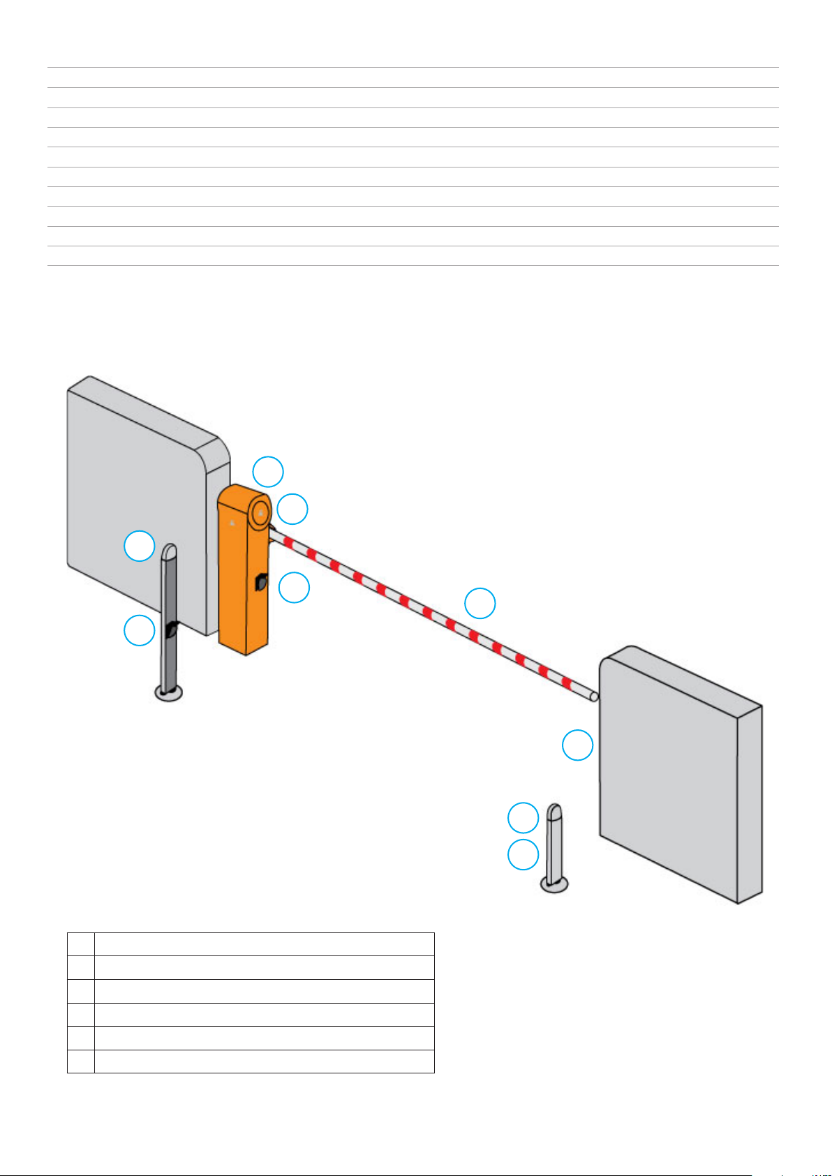
IMPIANTO TIPO
ITALIANO
1
6
5
3
2
3
3
3
4
1 Alzabarriera
2 Asta
3 Fotocellule
4 Colonnina Fotocellule
5 Selettore a chiave o digitale
6 Lampeggiante integrato su BRK
3
Page 4
ITALIANO
DIMENSIONI D’INGOMBRO
900BR4
900BR4-24
900BR-624
1000
220
320
900BR4-24K
845
8301051
400
280
900BR-624K
1110
220
320
845
1188
830
400
280
4
Page 5
PREPARAZIONE DELLA BASE PER L’AUTOMAZIONE
1. Prevedere uno scavo di fondazione e predisporre uno o più tubi per il passaggio dei cavi elettrici.
2. Assemblare le zanche sulla piastra di ancoraggio e ssarle tramite i 4 bulloni in dotazione.
3. Effettuare la colata di calcestruzzo all’interno dello scavo e posizionare la piastra di fondazione.
ATTENZIONE: vericare che la piastra sia perfettamente in bolla e parallela al varco di apertura.
4. Attendere la completa presa del calcestruzzo.
ITALIANO
5. Svitare i 4 dadi che tengono la base unita alle zanche e posizionare l’armadio sulla piastra.
NOTA: è consigliabile installare l’armadio con lo sportello di ispezione rivolto verso il lato più agevole.
Contro Piastra-BR
Contro Piastra-BR6
5
Page 6
ITALIANO
MONTAGGIO
Aprire l’imballo e vericare che tutti gli elementi che compongono l’automatismo siano integri.
Costruire una piazzola di ssaggio in cemento armato ed annegare la base di ancoraggio con
zanche (optional) ssate con i dadi in dotazione, vericare che sia perfettamente in bolla e che le
guaine di passaggio dei cavi attraversino il foro centrale della contro-piastra.
Posizionare la barriera vericando che non vi siano ostacoli al movimento dell’asta.
ATTENZIONE: non smontare mai per nessun motivo l’asta della barriera nché si trova in
posizione orizzontale e non eseguire mai la manovra di emergenza o manuale se l’asta non
è montata.
SBLOCCO
Nel caso sia necessario agire manualmente sull’asta della
barriera, operare come segue:
• Togliere l’alimentazione.
• Inserire la chiave di sblocco data in dotazione e togliere il
nottolino, inserire la chiave a brugola e ruotarla di 90°.
• In questo modo è possibile sganciare il sistema di riduzione interno per permettere la manovra di emergenza.
• Eseguire la manovra manuale.
• Per reinserire la trasmissione è sufciente ruotare la chiave
a brugola e riportarla nella posizione iniziale e poi chiudere la
serratura.
• A questo punto si può ripristinare l’alimentazione e vericare che tutto funzioni correttamente.
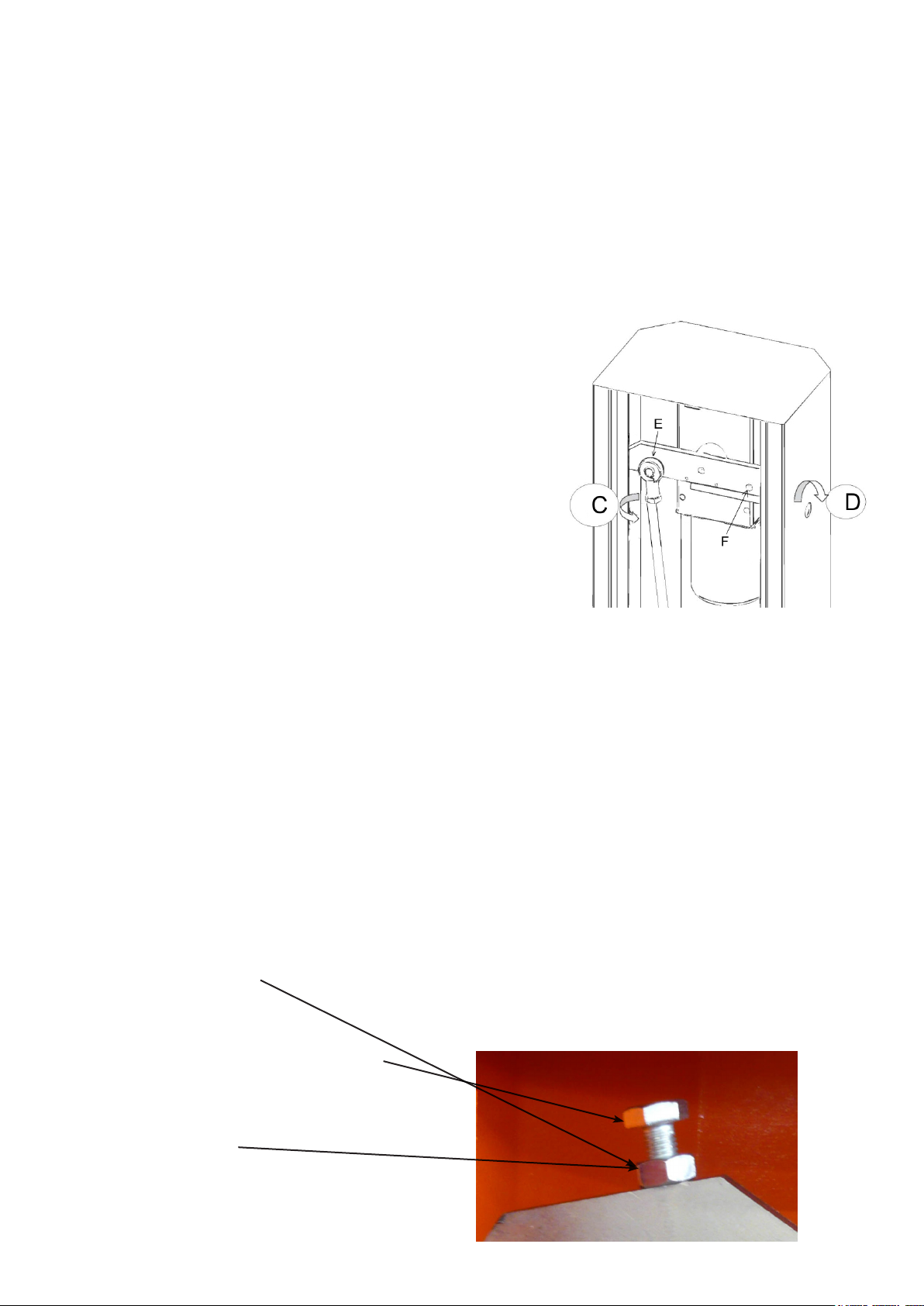
REGOLAZIONE ANGOLATURA ASTA
Nel caso in cui vi sia l’esigenza di regolare le battute di ne corsa dell’asta, bisogna procedere
come segue:
• Allentare il controdado (posto sul cassone per le BR4, BR4-24 e BR4-24K
o sul bilanciere per la BR-624 e BR-624K).
• Regolare la vite all’altezza desiderata.
• Fissare nuovamente il dado di bloccaggio.
Allentare il controdado
Regolare la vite all’altezza desiderata.
Fissare nuovamente il
dado di bloccaggio.
6
Page 7
INVERSIONE DEL SENSO DI APERTURA
Versione BR4, BR4-24 e BR4-24K
• Togliere l’alimentazione e con la manovra manuale (vedi procedura di sblocco) portare l’asta in
posizione verticale, ripristinare la trasmissione e togliere l’asta per evitare condizioni di pericolo.
• Aprire lo sportello, allentare il sistema di tensione della molla e successivamente sganciarla dal
ssaggio superiore.
• Togliere la vite di ssaggio così da liberare la molla nella parte superiore e permettere il suo posizionamento dal lato opposto della leva di ssaggio.
Versione BR-624 e BR-624K
• Togliere l’alimentazione e con la manovra manuale portare l’asta in posizione verticale, ripristinare
la trasmissione e togliere l’asta per evitare condizioni di pericolo.
• Aprire lo sportello, allentare il sistema di tensione delle molle e successivamente sganciare le
molle dal ssaggio superiore.
• Togliere le viti di ssaggio così da liberare le molle nella parte superiore e permettere il loro posizionamento dal lato opposto della leva di ssaggio.
• Svitare la leva in modo da consentirne la rotazione e permettere il ssaggio delle molle nella posi-
zione opposta.
• Fissare il tutto nelle posizioni indicate e tendere le molle (vedi paragrafo bilanciatura).
ITALIANO
BILANCIATURA
• Togliere l’alimentazione.
• Sbloccare l’asta (vedi g.2 rif.D).
• Posizionare l’asta circa a 45°:
• Allentare controdado/i del tenditore molla/e.
• Se l’asta tende a cadere agire sul tenditore molla/e in modo da farla fermare.
• Terminata la bilanciatura ssare nuovamente il controdado/i.
• Ripristinare il funzionamento motorizzato ruotando la chiave di sblocco nel verso opposto.
• Ripristinare l’alimentazione e vericare che tutto funzioni correttamente.
SMALTIMENTO
Questo prodotto è formato da vari componenti che potrebbero a loro volta contenere
sostanze inquinanti. Informarsi sul sistema di riciclaggio o smaltimento del prodotto atte-
nendosi alle norme di legge vigenti a livello locale.
NON DISPERDERE NELL’AMBIENTE!
7
Page 8
INDEX
IMPORTANT REMARKS 16
TECHNICAL FEATURES 17
INSTALLATION TYPE 17
EXTERNAL DIMENSIONS 18
INSTALLATION 18
ASSEMBLY 19
UNLOCK 19
ENGLISH
APPLICATION OF THE ARTICULATED ARM 20
ADJUSTMENT OF STOP MICROSWITCH 20
ELECTRICAL CONNECTION 21
PROGRAMMING 26
BATTERY 28
DISPOSAL 28
IMPORTANT REMARKS
For any installation problems please contact Key Automation S.p.A. TEL. (+39) 0421 307456
Key Automation S.p.A. has the right to modify the product without previous notice; it also declines any responsibility to
damage or injury to people or things caused by improper use or wrong installation.
Please read this instruction manual very carefully before installing and programming your control unit.
• This instruction manual is only for qualified technicians, who specialize in installations and automations.
• The contents of this instruction manual do not concern the end user.
• Every programming and/or every maintenance service should be done only by qualified technicians.
AUTOMATION MUST BE IMPLEMENTED IN COMPLIANCE WITH THE EUROPEAN REGULATIONS IN FORCE:
EN 60204-1 (Machinery safety. electrical equipment of machines, part 1: general rules)
EN 12445 (Safe use of automated locking devices, test methods)
EN 12453 (Safe use of automated locking devices, requirements)
• The installer must provide for a device (es. magnetotermical switch) ensuring the omnipolar sectioning of the equipment from the power supply. The standards require a separation of the contacts
of at least 3 mm in each pole (EN 60335-1).
• The plastic case has an IP55 insulation; to connect exible or rigid pipes, use pipettings having
the same insulation level.
• Installation requires mechanical and electrical skills, therefore it shall be carried out by qualied
personnel only, who can issue the Compliance Certicate concerning the whole installation (Ma-
chine Directive 2006/42/CEE, Annex IIA).
• The automated vehicular gates shall comply with the following rules: EN 13241-1, EN 12453, EN
12445 as well as any local rule in force.
• Also the automation upstream electric system shall comply with the laws and rules in force and be
carried out workmanlike.
• The door thrust force adjustment shall be measured by means of a proper tool and adjusted according to the max. limits, which EN 12453 allows.
• We recommend to make use of an emergency button, to be installed by the automation (connected to the control unit STOP input) so that the gate may be immediately stopped in case of danger.
• The appliance is not to be used by children or persons with reduced physical, sensory or mental capabilities, or lack of experience and knowledge, unless they have been given supervision or
instruction.
• Children being supervised do not play with the appliance.
8
Page 9
MODELS AND CHARACTERISTICS 900BR4 900BR4-24 900BR-624 900BR4-24K 900BR-624K
Control unit CT-101 CT-24SBA CT-24SBA CT-24SBA CT-24SBA
Power supply 230 Vac 24 Vdc 24 Vdc 24 Vdc 24 Vdc
Input power 155 W 150 W 150 W 150 W 150 W
Motor revs 1400 rpm 1200 rpm 1200 rpm 1200 rpm 1200 rpm
Motor absorption 0,67 A 6 A 6 A 6 A 6 A
Condenser 8 µF - - - Opening time 4,5 sec 5 sec 10 sec 5 sec 10 sec
Maximum length of rod 4 m 4 m 6 m 4 m 6 m
Temporary service 60 % 80 % 80 % 80 % 80 %
Operating temperature -20° +70°C -20° +70°C -20° +70°C -20° +70°C -20° +70°C
Weight 35 Kg 35 Kg 43 Kg 35 Kg 43 Kg
INSTALLATION TYPE
ENGLISH
1
6
5
3
2
3
3
3
4
1 Barrier gate
2 rod
3 Photocellules
4 Photocell column
5 Key or digital operated selector switch
6 Flashing light on the BRK
9
Page 10
ENGLISH
900BR4
900BR4-24
OVERALL DIMENSIONS
900BR-624
1000
220
320
900BR4-24K
845
8301051
400
280
900BR-624K
1110
220
320
845
1188
830
400
280
10
Page 11

PREPARATION FOR AUTOMATION OF THE BASE
1. Provide a foundation pit and arrange one or more conduits for the passage of the electrical cabling.
2. Assemble the 4 anchoring brackets on the mounting plate and fasten with the 4 bolts provided.
3. Pour the concrete into the inside of the pit and position the base plate.
NOTE: verify that the plate is perfectly leveled and parallel to the opening barrier.
4. Wait for the complete setting of the concrete.
ENGLISH
5. Unscrew the 4 nuts that hold the base joined to the anchoring brackets and position the rack on
the plate.
mounting plate-BR
mounting plate-BR6
11
Page 12
ASSEMBLY
Open the packaging and check the condition of all the parts of the automation.
Construct a fastening pad in reinforced concrete and sink the anchoring base with tangs (optional)
fastened with the nuts provided.
Check that it is perfectly level and that the cable passage sheaths cross the centre hole of the
counter-plate.
Position the barrier and check that there are no obstacles to the movement of the rod.
ATTENTION: never move the barrier rod for any reason until it is horizontal, and do not per-
ENGLISH
form the emergency or manual manoeuvre if the rod is not installed.
RELEASE
If you need to perform manual actions on the barrier rod,
proceed as follows:
• Cut the power supply.
• Insert the release key provided and remove the latch,
insert the Allen wrench and turn it 90° (see g. 2 ref. D).
• In this way you can detach the internal reduction sys-
tem to allow the emergency manoeuvre.
• Perform the manual manoeuvre.
• To engage the transmission again, turn the Allen
wrench back to its original position and close the lock.
• You can now restore the power supply and check that
everything is working correctly.
ADJUSTMENT OF ROD ANGLE
If you need to adjust the stops of the rods, proceed as follows:
• Loosen the locking nut (located on the box for BR-V, BR4-24 and BR4-24K or on the rocker
arm for BR-624 and BR-624K).
• Adjust the screw to the desired height.
• Fasten the locking nut back in place.
Loosen the lock nut
Adjust the screw to the desired height.
Fasten the lock nut.
12
Page 13

INVERSION OF DIRECTION OF OPENING AND BALANCING
Version BR-V, BR4-24 and BR4-24K
• Turn off the power supply and, with the manual manoeuvre, place the rod vertical, restore
the transmission and remove the rod to prevent hazardous conditions.
• Open the door, loosen the tension system of the spring and then release it from the upper
fastening.
• Remove the fastening screw so as to free the spring in the upper part and allow it to be positioned on the opposite side of the fastening lever.
Version BR-624 and BR-624K
• Turn off the power supply and, with the manual manoeuvre, place the rod vertical, restore
the transmission and remove the rod to prevent hazardous conditions.
• Open the door, loosen the tension system of the springs and then release the springs from
the upper fastening.
• Remove the fastening screws so as to free the springs in the upper part and allow them to
be positioned on the opposite side of the fastening lever.
• Unscrew the lever so as to allow it to rotate and allow fastening of the springs in the opposite position.
• Fasten all in the indicated positions and tension the springs (see the paragraph on balancing).
ENGLISH
BALANCING
• Cut the power supply.
• Release the rod.
• Position the rod at about 45°.
• Loosen the locking nut(s) of the spring tensioner(s).
• If the rod tends to fall, adjust the spring tensioner(s) so that it is stopped.
• When balancing is complete, fasten the locking nut(s) again.
• Restore motorized operation by turning the release key in the opposite direction.
• Restore the power supply and check that everything works correctly.
DISPOSAL
This product is composed of various components which may in turn contain pollutants.
Do not dispose of it in the environment! Find out about the method for recycling or disposing of the product in compliance with current local laws
13
Page 14
INDEX
CONSEILS IMPORTANTS 30
CARACTÉRISTIQUES TECHNIQUES 31
SCHÉMA D’INSTALLATION 31
LONGUEUR MAX DE LA PORTE 32
FIXATION DU BRAS AU PORTAIL 32
MONTAGE 33
DÉBLOCAGE 33
APPLICATION DU BRAS ARTICULÉ 34
RÉGLAGE FIN DE COURSE CAMES 34
BRANCHEMENTS ÉLECTRIQUES 35
PROGRAMMATION 40
CHARGEUR DE BATTERIE 42
MISE AU REBUT 42
CONSEILS IMPORTANTS
FRANÇAIS
Pour tout précision technique ou problème d’installation Key Automation S.p.A. dispose d’un service d’assistance
clients actif pendant les horaires de bureau
TEL. (+39) 0421 307456
Key Automation S.p.A. se réserve le droit d’apporter d’éventuelles modifications au produit sans préavis; elle décline
en outre toute responsabilité pour tous types de dommages aux personnes ou aux choses dus à une utilisation
impropre ou à une mauvaise installation.
Avant de procéder avec l’installation et la programmation, lire attentivement les notices.
• Ce manuel d’instruction est destiné à des techniciens qualifiés dans le domaine des automatismes.
• Aucune des informations contenues dans ce livret pourra être utile pour le particulier.
• Tous opérations de maintenance ou programmation doivent être faites à travers de techniciens qualifiés.
L’AUTOMATION DOIT ÊTRE RÉALISÉE CONFORMÉMENT AUX DISPOSITIFS NORMATIFS
EUROPÉENS EN VIGUEUR:
EN 60204-1 (Sécurité de la machinerie. Équipement électrique des machines, partie 1: réglés générales).
EN 12445 (Sécurité dans l’utilisation de fermetures automatisées, méthodes d’essai).
EN 12453 (Sécurité dans l’utilisation de fermetures automatisées, conditions requises).
L’installateur doit pourvoir à l’installation d’un dispositif (ex. interrupteur magnétothermique) qui assure la coupure
omnipolaire de l’équipement du réseau d’alimentation. La norme requiert une séparation des contacts d’au moins 3
mm pour chaque pôle (EN 60335-1).
• L’enveloppe en plastique de la carte possède une protection IP55, pour la connexion de tubes rigides ou flexibles
utiliser des raccordements possédant le même niveau de protection.
• L’installation requiert des compétences en matière d’électricité et mécaniques; doit être faite exclusivement par techniciens qualifiés en mesure de délivrer l’attestation de conformité pour l’installation (Directive 2006/42/CEE, - IIA).
• Il est obligatoire se conformer aux normes suivantes pour fermetures véhiculaires automatisées: EN 13241-1, EN
12453, EN 12445 et à toutes éventuelles prescriptions nationales.
• Même l’installation électrique ou on branche l’automatisme doit répondre aux normes en vigueur et être fait à règles
del’art.
• La régulation de la force de poussée du vantail doit être mesurée avec outil spécial et réglée selon les valeurs maxi
admis par la norme EN 12453.
• Nous conseillons d’utiliser un poussoir d’urgence à installer près de l’automatisme (branché à l’entrée STOP de
l’armoire de commande de façon qui soit possible l’arrêt immédiat du portail en cas de danger.
• L’appareillage ne doit pas être utilisé par des enfants ou des personnes affectés d’handicaps physiques et/ou psychiques, sans la nécessaire connaissance ou supervision de la part d’une personne compétente.
• Veillez à ce que les enfants ne puissent jouer avec l’appareillage.
Avant d’effectuer toute intervention sur l’installation, couper l’alimentation électrique et débrancher
les batteries.
14
Page 15
MODÈLES ET CARACTÉRISTIQUES 900BR4 900BR4-24 900BR-624 900BR4-24K 900BR-624K
Centrale CT-101 CT-24SBA CT-24SBA CT-24SBA CT-24SBA
Alimentation 230 Vac 24 Vdc 24 Vdc 24 Vdc 24 Vdc
Puissance absorbée 155 W 150 W 150 W 150 W 150 W
Tours du moteur 1400 rpm 1200 rpm 1200 rpm 1200 rpm 1200 rpm
Absorption du moteur 0,67 A 6 A 6 A 6 A 6 A
Condenseur 8 µF - - - Temps d'ouverture 4,5 sec 5 sec 10 sec 5 sec 10 sec
Longueur max. barre 4 m 4 m 6 m 4 m 6 m
Service temporaire 60 % 80 % 80 % 80 % 80 %
Température de fonctionnement -20° +70°C -20° +70°C -20° +70°C -20° +70°C -20° +70°C
Poids 35 Kg 35 Kg 43 Kg 35 Kg 43 Kg
SCHÉMA D’INSTALLATION
1
FRANÇAIS
6
5
3
2
3
3
3
4
1 Barrière de porte
2 Enchères
3 Cellules photoélectriques
4 Photocellule
5 Key ou numérique
6 Intégrée à clignoter sur BRK
15
Page 16

DIMENSIONS D’ENCOMBREMENT
900BR4
900BR4-24
900BR-624
FRANÇAIS
1000
220
320
900BR4-24K
845
8301051
400
280
900BR-624K
1110
220
320
845
1188
830
400
280
16
Page 17

PRÉPARATION DE LA BASE POUR L’AUTOMATION
1. Prédisposer un trou de fondation et un ou plusieurs tubes pour le passage câbles électriques.
2. Assembler les 4 agrafes sur la plaque d’ancrage et les xer au moyen des 4 boulons en dotation.
3. Effectuer la coulée de béton à l#intérieur de l’excavation et positionner la plaque de fondation.
ATTENTION: vérier que la plaque soit parfaitement en bulle et parallèle au passe d’ouverture.
4. Attendre la prise complète du béton.
5. Dévisser les 4 dés qui tiennent la base reliée aux agrafes et positionner l’armoire de commande
sur la plaque.
REMARQUE: il est conseillé d’installer l’armoire avec la trappe de visite tournée vers le côté aisé-
ment accessible.
Plaque-BR
Plaque-BR6
FRANÇAIS
17
Page 18

MONTAGE
Ouvrir l'emballage et contrôler le bon état de tous les composants de l’automatisme.
Construire une plateforme de xation en béton armé et y insérer la base d'ancrage avec pattes
(option), xées avec les écrous fournis.
Vérier qu'elle soit parfaitement à niveau et que les gaines de passage des câbles traversent le
trou central de la contre-plaque.
Positionner la barrière en vériant qu'aucun obstacle n'empêche le mouvement de la barre.
ATTENTION : ne démonter jamais et pour aucune raison la barre de la barrière tant que
celle-ci se trouve en position horizontale et n'effectuer jamais la manœuvre d'urgence ou
manuelle si la barre n'est pas montée.
DÉBLOCAGE
Si nécessaire, agir manuellement sur la barre de la barrière
FRANÇAIS
et procéder comme suit :
• Couper l’alimentation.
• Insérer la clé de déblocage fournie et retirer le loque-
teau, insérer la clé à six pans et la tourner de 90°.
• De cette manière, il est possible de décrocher le
système de réduction interne an de permettre la manœuvre
d’urgence.
• Effectuer la manœuvre manuelle.
• Pour réenclencher la transmission, il suft de tourner
la clé à six pans pour la remettre dans la position initiale et
de fermer la serrure.
• Il est maintenant possible de rétablir l’alimentation et
de vérier que tout fonctionne correctement.
RÉGLAGE DE L’ANGLE DE LA BARRE
Pour régler les butées de n de course, procéder comme suit :
• Desserrer le contre-écrou (situé sur le coffre pour les BR-V, BR4-24 et BR4-24K ou sur le
balancier pour les BR-624 et BR-624K).
• Régler la vis à la hauteur souhaitée.
• Fixer de nouveau l’écrou de blocage.
Desserrer l’écrou de blocage
Régler la vis à la hauteur désirée.
Serrer l’écrou de blocage.
18
Page 19

INVERSION DU SENS D’OUVERTURE ET D’ÉQUILIBRAGE
Versions BR-V, BR4-24 et BR4-24K
• Couper l’alimentation et avec la manœuvre manuelle amener la barre en position verticale,
rétablir la transmission et retirer la barre an d’éviter tout condition de danger.
• Ouvrir le volet, desserrer le système de tension du ressort et le décrocher de la xation
supérieure.
• Retirer la vis de xation an de libérer le ressort dans la partie supérieure et de permettre
son positionnement sur le côté opposé au levier de xation.
Versions BR-624 et BR-624K
• Couper l’alimentation et avec la manœuvre manuelle amener la barre en position verticale,
rétablir la transmission et retirer la barre an d’éviter tout condition de danger.
• Ouvrir le volet, desserrer le système de tension des ressorts et décrocher les ressorts de la
xation supérieure.
• Retirer les vis de xation an de libérer les ressorts dans la partie supérieure et de permettre
leur positionnement sur le côté opposé au levier de xation.
• Dévisser le levier de manière à en faciliter la rotation et à permettre la xation des ressorts
dans la position opposée.
• Fixer le tout dans les positions indiquées et tendre les ressorts (voir paragraphe équilibrage).
ÉQUILIBRAGE
• Couper l’alimentation.
• Débloquer la barre.
• Positionner la barre à environ 45° :
• Desserrer le/s contre-écrou/s du tendeur de ressort/s.
• Si la barre a tendance à tomber, agir sur le tendeur de ressort/s de manière à l’arrêter.
• Une fois l’équilibrage terminé, xer de nouveau le/s contre-écrou/s.
• Rétablir le fonctionnement motorisé en tournant la clé de déblocage dans le sens opposé.
• Rétablir l’alimentation et vérier que tout fonctionne correctement.
FRANÇAIS
ÉLIMINATION
Ce produit est composé de différents éléments susceptibles de contenir à leur tour des
substances polluantes. Ne pas rejeter dans l’environnement. Se renseigner sur le système de recyclage ou d’élimination du produit en respectant les réglementations locales
en vigueur.
NE PAS JETER DANS L’ENVIRONNEMENT !
19
Page 20

INHALTSVERZEICHNIS
WICHTIGE HINWEISE 44
TECHNISCHE EIGENSCHAFTEN 45
IMPIANTO TIPO 45
PLATZBEDARF 46
BEFESTIGUNG 46
MONTAGE 47
ENTRIEGELUNG 47
ANBRINGUNG DES GELENKARMS 48
REGULIERUNG ENDSCHALTERNOCKEN 48
ELEKTRISCHE ANSCHLÜSSE 49
PROGRAMMIERUNG 54
BATTERIELADEGERÄT 56
ENTSORGUNG 56
WICHTIGE HINWEISE
Für tecnische Erläuterungen oder Installtionsprobleme verfügt die Firma Key Automation S.p.A. über einen Kundendienst, der zu Bürozeiten unter der Telefonnummer TEL. (+39) 0421 307456 erreicht werden kann.
Die Firma Key Automation S.p.A. behält sich das Recht vor, das Produkt ohne vorherige Ankündigungen abzuän-
dern; die Übernahme der Haftung für Schäden an Personen oder Sachen, die auf einen unsachgemäßen Gebrauch
oder eine fehlerhafte Installation zurückzuführen sind, wird abgelehnt.
Um die Steuerung fehlerfrei zu installieren und programmieren zu können, lesen Sie bitte diese
DEUTSCH
• Diese Bedienungsanleitung ist nur für Fachtechniker, die auf Installationen und Automationen von Toren.
• Keine Information dieser Bedienungsanleitung ist für den Endbenutzer nützlich.
• Jede Programmierung und/oder jede Wartung sollte nur von geschulten Technikern vorgenommen werden.
DIE AUTOMATISIERUNG MUSS IN ÜBEREINSTIMMUNG MIT DEN GELTENDEN EUROPÄISCHEN NORMEN ERFOLGEN:
EN 60204-1 (Sicherheit der Maschine elektrische Ausrüstungen von Maschinen, Teil 1: allgemeine Anforderungen)
EN 12445 (Nutzungssicherheit kraftbetätigter Tore rüfverfahren)
EN 12453 (Nutzungssicherheit kraftbetätigter Tore Anforderungen)
• Der Installateur muss eine Vorrichtung (z.B. thermomagn. Schalter) anbringen, die Trennung aller Pole des Geräts
zum Versorgungsnetz garantiert. Die Norm verlangt eine Trennung der Kontakte von mindestens 3 mm an jedem
Pol (EN 60335-1).
• Für den Anschluss von Rohren und Schläuchen oder Kabeldurchgängen sind Verbindungen zu verwenden, die
dem Sicherungsgrad IP55 entsprechen.
• Die Installation erfordert Kenntnisse auf den Gebieten der Elektrik und Mechanik; sie darf ausschließlich von kompetentem Personal durchgeführt werden, welches berechtigt ist, eine vollständige Konformitätserklärung vom Typ A
auszustellen (Maschinenrichtlinie 2006/42/CEE, Anlage IIA).
• Für automatisch betriebene Rolltore ist die Einhaltung der folgenden Normen obligatorisch: EN 13241-1, EN 12453,
EN 12445 und alle eventuell geltenden, regionalen Vorschriften.
• Auch die elektrische Anlage der Automatik muss den geltenden Normen genügen, und fachgerecht installiert werden.
• Die Schubkraft des Torflügels muss mit Hilfe eines geeigneten Instruments gemessen, und entsprechend den in
Richtlinie EN 12453 definierten Höchstwerten eingestellt werden.
• Es wird empfohlen, in der Nähe der Automatik einen NotausSchalter zu installieren (mit Anschluss an en Eingang
STOP der Steuerkarte), so dass bei Gefahr ein unverzügliches Halten des Tors bewirkt werden kann.
• Das Gerät darf nicht von körperlich oder psychisch behinderten Kindern oder Personen ohne entsprechende
Kenntnisse oder Aufsicht seitens einer kompetenten Person betätigt werden.
• Kinder so beaufsichtigen, dass sie nicht mit dem Gerät spielen.
Vor jedem Eingriff an der Anlage müssen erst die Stromversorgung und die Batterien abgetrennt
werden.
Bedienungsanleitung sehr aufmerksam durch.
20
Page 21

MODELLE UND MERKMALE 900BR4 900BR4-24 900BR-624 900BR4-24K 900BR-624K
Steuereinheit CT-101 CT-24SBA CT-24SBA CT-24SBA CT-24SBA
Speisung 230 Vac 24 Vdc 24 Vdc 24 Vdc 24 Vdc
Leistungsaufnahme 155 W 150 W 150 W 150 W 150 W
Motorumdrehungen 1400 rpm 1200 rpm 1200 rpm 1200 rpm 1200 rpm
Stromaufnahme Motor 0,67 A 6 A 6 A 6 A 6 A
Kondensator 8 µF - - - Öffnungszeit 4,5 sec 5 sec 10 sec 5 sec 10 sec
Max. Länge Balken 4 m 4 m 6 m 4 m 6 m
Überbrückungsbetrieb 60 % 80 % 80 % 80 % 80 %
Betriebstemperatur -20° +70°C -20° +70°C -20° +70°C -20° +70°C -20° +70°C
Gewicht 35 Kg 35 Kg 43 Kg 35 Kg 43 Kg
INSTALLATIONSPLAN
1
6
5
3
2
DEUTSCH
3
3
3
4
1 Schranke
2 Auktion
3 Lichtschranken
4 Fotozelle
5 Key oder digitalen
6
Blinkvorrichtung auf BRK integriert
21
Page 22

RAUMBEDARF
900BR4
900BR4-24
900BR-624
DEUTSCH
1000
220
320
900BR4-24K
845
8301051
400
280
900BR-624K
1110
220
320
845
1188
830
400
280
22
Page 23

BASIS DER VORBEREITUNG FÜR DIE AUTOMATION
1. Eine Grundlage Loch und bereiten ein oder mehrere Rohre für den Durchgang von elektrischen
Kabeln.
2. Montieren Sie die Klemmen auf der Platte und befestigen Sie sie mit den 4 Schrauben.
3. Making das Gießen von Beton in das Loch und die Platte.
ACHTUNG: Achten Sie darauf, die Platte ist vollkommen eben und parallel zu der Toröffnung.
4. Warten Sie die vollständige Einstellung des Betons.
5. Lösen Sie die 4 Muttern, dass die Basis halten zusammen mit den Klammern und platzieren Sie
den Schrank auf der Platte.
HINWEIS: Kunden sollten den Schrank mit der Tür zugewandten Seite der Inspektion einfacher zu
installieren.
Montageplatte-BR
Montageplatte-BR6
DEUTSCH
23
Page 24

MONTAGE
Öffnen Sie die Verpackung und stellen Sie sicher, dass alle einzelnen Komponenten des Antriebs
unbeschädigt sind.
Eine Befestigungsplattform aus Stahlbeton herstellen und die Verankerungsbasis mit Krampen
(optional) versenken, die mit den mitgelieferten Muttern befestigt werden.
Sicherstellen, dass sie perfekt horizontal ausgerichtet ist und die Mäntel der Kabel die mittlere Boh-
rung der Gegenplatte durchqueren.
Die Schranke positionieren und sicherstellen, dass die Bewegung des Balkens nicht behindert
wird.
ACHTUNG: aus keinem Grund den Balken der Schranke abmontieren, so lange er sich in
horizontaler Position bendet und niemals eine Notbewegung oder manuelle Bewegung
ausführen, wenn der Balken nicht montiert ist.
ENTRIEGELUNG
Falls manuell auf den Balken der Schranke eingewirkt wer-
den muss, wie folgt vorgehen:
• Stromversorgung abtrennen.
• Den mitgelieferten Entriegelungsschlüssel einsetzen
und die Klinke entfernen. Den Inbusschlüssel einsetzen und
um 90° drehen.
• So kann das interne Getriebesystem ausgeklinkt werden, um die Notbewegung zu gestatten.
• Die manuelle Bewegung ausführen.
DEUTSCH
• Um das Getriebe wieder zu aktivieren, reicht es, den
Inbusschlüssel zu drehen und ihn in die Ausgangsposition zu
bringen und dann das Schloss zu schließen.
• Jetzt kann die Stromversorgung wieder hergestellt
werden und sichergestellt werden, dass alles korrekt funktioniert.
EINSTELLUNG DES BALKENWINKELS
Falls die Endanschläge des Balkens eingestellt werden müssen, wie folgt vorgehen:
• Die Kontermutter lockern (die sich für BR-V, BR4-24 und BR4-24K am Gehäuse und für BR624 und BR-624K am Kipphebel bendet).
• Die Schraube auf der gewünschten Höhe einstellen.
• Erneut die Arretiermutter befestigen.
Lösen Sie die Kontermutter
Stellen Sie die Schraube in die
gewünschte Höhe.
Ziehen Sie die Kontermutter.
24
Page 25

UMKEHR DER ÖFFNUNGSRICHTUNG UND AUSRICHTUNG
Ausführung BR-V, BR4-24 und BR4-24K
• Die Stromversorgung abtrennen und mit manueller Bewegung den Balken in die vertikale
Position bringen. Das Getriebe wieder anschließen, und den Balken abnehmen, um Gefahrensitua-
tionen zu vermeiden.
• Die Klappe öffnen, das Spannsystem der Feder lockern und diese dann von der oberen Befestigung ausklinken.
• Die Befestigungsschraube entfernen, um die Feder im oberen Teil freizusetzen und ihre Positionierung auf der gegenüberliegenden Seite des Befestigungshebels zu gestatten .
Ausführung BR-624 und BR-624K
• Die Stromversorgung abtrennen und mit manueller Bewegung den Balken in die vertikale
Position bringen. Das Getriebe wieder anschließen, und den Balken abnehmen, um Gefahrensitua-
tionen zu vermeiden.
• Die Klappe öffnen, das Spannsystem der Federn lockern und diese dann von der oberen
Befestigung ausklinken.
• Die Befestigungsschrauben entfernen, um die Federn im oberen Teil freizusetzen und ihre
Positionierung auf der gegenüberliegenden Seite des Befestigungshebels zu gestatten.
• Den Hebel abschrauben, damit er gedreht werden kann und die Befestigung der Federn in
entgegengesetzter Position möglich ist.
• Alles in den angegebenen Positionen befestigen und die Federn spannen (siehe Absatz
Ausrichtung).
AUSRICHTUNG
• Stromversorgung abtrennen.
• Den Balken entriegeln.
• Den Balken auf zirka 45° positionieren:
• Die Kontermutter/n des Spanners der Feder/n lockern.
• Wenn der Balken zu fallen droht, auf den Spanner der Feder/n einwirken, damit dieser anhält.
• Wenn die Ausrichtung beendet ist, die Kontermutter/n erneut befestigen.
• Den Motorbetrieb wieder herstellen, indem man den Entriegelungsschlüssel in die andere
Richtung dreht.
• Die Stromversorgung wieder herstellen, und sicherstellen, dass alles korrekt funktioniert.
ENTSORGUNG
Dieses Produkt setzt sich aus verschiedenen Bauteilen zusammen, die umweltbelastende Substanzen enthalten könnten. Umweltfreundlich entsorgen! Sich über die Wiederverwertung und Entsorgung des Produkts in Übereinstimmung mit den örtlich geltenden,
gesetzlichen Vorschriften informieren.
NICHT IN DER UMWELT VERWAHRLOSEN!
DEUTSCH
25
Page 26

ÍNDICE
ADVERTENCIAS IMPORTANTES 58
CARACTERÍSTICAS TÉCNICAS 59
ESQUEMA DE INSTALACIÓN 59
DIMENSIONES TOTALES 60
FIJACIÓN 60
MONTAJE 61
DESBLOQUEO 61
APLICACIÓN DEL BRAZO ARTICULADO 62
REGULACIÓN DE LOS FINES DE CARRERA DE LAS LEVAS 62
CONEXIONES ELÉCTRICAS 63
PROGRAMACIÓN 68
CARGADOR DE BATERÍA 70
ELIMINACIÓN 70
ADVERTENCIAS IMPORTANTES
Por cualquier problema técnico ponerse en contacto con el servicio asistencia Key Automation S.p.A.
TEL. (+39) 0421 307456
Key Automation S.p.A. se reserva el derecho de aportar eventuales modificaciones al producto sin previo aviso; además, no se hace responsable de daños a personas o cosas debidos a un uso impropio o a una instalación errónea.
Antes de proceder a la instalación y programación es aconsejable leer bien las instrucciones.
• Dicho manual está destinado exclusivamente a técnicos calificados en las instalaciones de automatismos.
• Ninguna de las informacciones contenidas en dicho manual puede ser de utilidad para el usuario final.
• Cualquier operación de mantenimiento y programación tendrá que ser hecha por técnicos calificados en las instala-
ciones de automatismos.
LA AUTOMATIZACION DEBE SER REALIZADA EN CONFORMIDAD A LAS VIGENTES NORMATIVAS EUROPEAS:
EN 60204-1 (Seguridad de la maquinaria. Equipamiento eléctrico de las máquinas, partes 1: reglas generales).
ESPAÑOL
EN 12445 (Seguridad en el uso de cierres automatizados, metodos de prueba)
EN 12453 (Seguridad en el uso de cierres automatizados, requisitos)
• El instalador debe proveer la instalación de un dispositivo (ej. interruptor magnetotérmico) que asegure el seccionamiento omnipolar del aparato de la red de alimentación. La normativa requiere una separación de loscontactos de
mínimo 3 mm en cada polo (EN 60335-1).
• Para la conexión de tubos rígidos o flexibles y pasacables, utilizar manguitos conformes al grado de protección IP55
como la caja de plástico que contiene la placa.
• La instalación requiere competencias en el campo eléctricoy mecánico; debe ser realizada únicamente por personal cualificado en grado de expedir la declaración de conformidad en la instalación (Directiva máquinas 2006/42/
CEE, anexo IIA).
•• Es obligatorio atenerse a las siguientes normas para cierres automatizados con paso de vehículos: EN 13241-1,
EN 12453, EN 12445 y a las eventuales prescripciones nacionales.
• Incluso la instalación eléctrica antes de la automatización debe responder a las vigentes normativas y estar realizada correctamente.
• La regulación de la fuerza de empuje de la hoja debe medirse con un instrumento adecuado y regulada de acuerdo
con los valores máximos admitidos por la normativa EN 12453.
• El equipo no debe ser utilizado por infantes o personas con discapacidades físicas o psíquicas, sin el debido conocimiento o supervisión por parte de una persona competente.
• Vigile a los niños de modo que no jueguen con el equipo.
Antes de realizar cualquier operación en la instalación, corte la alimentación eléctrica y desconecte
las baterías.
26
Page 27

MODELOS Y CARACTERÍSTICAS 900BR4 900BR4-24 900BR-624 900BR4-24K 900BR-624K
Centralita CT-101 CT-24SBA CT-24SBA CT-24SBA CT-24SBA
Alimentación 230 Vac 24 Vdc 24 Vdc 24 Vdc 24 Vdc
Potencia consumida 155 W 150 W 150 W 150 W 150 W
Revoluciones del motor 1400 rpm 1200 rpm 1200 rpm 1200 rpm 1200 rpm
Consumo del motor 0,67 A 6 A 6 A 6 A 6 A
Condensador 8 µF - - - Tiempo de apertura 4,5 sec 5 sec 10 sec 5 sec 10 sec
Longitud máx. de la barra 4 m 4 m 6 m 4 m 6 m
Servicio temporal 60 % 80 % 80 % 80 % 80 %
Temperatura de funcionamiento -20° +70°C -20° +70°C -20° +70°C -20° +70°C -20° +70°C
Peso 35 Kg 35 Kg 43 Kg 35 Kg 43 Kg
ESQUEMA DE INSTALACIÓN
1
6
5
3
2
3
3
ESPAÑOL
3
4
1 Barrera de puerta
2 Subastas
3 Fotocélulas
4 Célula fotoeléctrica
5 Clave o digital
6 Integrado a parpadear en BRK
27
Page 28

DIMENSIONES
900BR4
900BR4-24
900BR-624
1000
220
320
900BR4-24K
845
8301051
400
280
900BR-624K
ESPAÑOL
1110
320
845
1188
830
400
220
280
28
Page 29

PREPARACIÓN DE LA BASE PARA LA AUTOMATIZACIÓN
1. Disponga de una excavación de cimentación y predisponga de uno o más tubos para el paso de
los cables eléctricos.
2. Monte los cuatro soportes sobre la placa de anclaje y fíjela mediante los cuatro pernos suministrados.
3. Efectúe la colada de hormigón al interior de la excavación y coloque la placa de cimentación.
ATENCIÓN: compruebe que la placa esté perfectamente horizontal y paralela al paso de la
apertura.
4. Espere la fragua completa del hormigón.
5. Enrosque las cuatro tuercas que tienen la base unida a los soportes y coloque el armario sobre
la placa.
NOTA: Se recomienda instalar el armario con la mirilla de inspección dirigida hacia el lado más
conveniente.
Placa de montaje-BR
Placa de montaje-BR6
ESPAÑOL
29
Page 30

DESBLOQUEO
Si fuese necesario intervenir manualmente sobre la barra de
la barrera, siga estas instrucciones:
• Corte la alimentación.
• Introduzca la llave de desbloqueo suministrada y ex-
traiga el cilindro, introduzca la llave Allen y gírela 90° .
• De esta manera se puede desenganchar el sistema
de reducción interno para permitir la maniobra de emergencia.
• Efectúe la maniobra manual.
• Para volver a activar la transmisión basta girar la llave
Allen, volver a colocarla en la posición inicial y después cerrar la cerradura.
• A continuación se puede restablecer la alimentación y
comprobar que todo funcione correctamente.
AJUSTE DEL ÁNGULO DE LA BARRA
Si se necesitase ajustar los topes de n de carrera de la barra, será necesario seguir estas instrucciones:
• Aoje la contratuerca (situada en la caja para las BR-V, BR4-24 y BR4-24K o en el balancín
para las BR-624 y BR-624K).
• Ajuste el tornillo a la altura deseada.
• Vuelva a jar la tuerca de bloqueo.
Aoje la tuerca de seguridad
ESPAÑOL
Ajuste el tornillo a la altura deseada.
Apretar la tuerca de seguridad.
30
Page 31

INVERSIÓN DEL SENTIDO DE APERTURA Y EQUILIBRADO
Versión BR-V, BR4-24 y BR4-24K
• Corte la alimentación y, con la maniobra manual, ponga la barra en posición vertical. Restablezca la transmisión y extraiga la barra para evitar situaciones peligrosas.
• Abra la portezuela, aoje el sistema de tensado del muelle y después extráigalo de la jación superior.
• Extraiga el tornillo de jación para liberar el muelle en la parte superior y permitir su colocación en el lado opuesto de la palanca de jación.
Versión BR-624 y BR-624K
• Corte la alimentación y, con la maniobra manual, ponga la barra en posición vertical. Restablezca la transmisión y extraiga la barra para evitar situaciones peligrosas.
• Abra la portezuela, aoje el sistema de tensado de los muelles y después desenganche los
muelles de la jación superior.
• Extraiga los tornillos de jación para liberar los muelles en la parte superior y permitir su
colocación en el lado opuesto de la palanca de jación.
• Desatornille la palanca para permitir su rotación y permitir la jación de los muelles en la
posición opuesta.
• Fije el conjunto en las posiciones indicadas y tense los muelles (vea el apartado de equilibrado).
EQUILIBRADO
• Corte la alimentación.
• Desbloquee la barra.
• Coloque la barra a aproximadamente 45°:
• Aoje la contratuerca/s del tensor del muelle/s.
• Si la barra tiende a caer, intervenga sobre el tensor del muelle/s para detenerla.
• Una vez concluido el equilibrado, vuelva a jar la contratuerca/s.
• Restablezca el funcionamiento motorizado girando la llave de desbloqueo en el sentido opuesto.
• Restablezca la alimentación y compruebe que todo funcione correctamente.
ELIMINACIÓN
Este producto esta formado por diversos componentes que podrían a su vez contener sustancias contaminantes. No lo expulse al medio ambiente. Infórmese acerca del sistema de
reciclaje o eliminación del producto, respetando las normas de ley vigentes a nivel local.
EVÍTESE SU LIBERACIÓN AL MEDIO AMBIENTE.
31
ESPAÑOL
Page 32

SUMÁRIO
AVISOS IMPORTANTES 72
CARACTERÍSTICAS TÉCNICAS 73
INSTALAÇÃO TIPO 73
DIMENSÕES TOTAIS 74
FIXAÇÃO 74
MONTAGEM 75
DESBLOQUEIO 75
APLICAÇÃO DO BRAÇO ARTICULADO 76
REGULAÇÃO DO FIM DE CURSO DO CAME 76
LIGAÇÕES ELÉCTRICAS 77
PROGRAMAÇÃO 82
CARREGADOR DE BATERIA 84
ELIMINAÇÃO 84
AVISOS IMPORTANTES
Para esclarecimentos técnicos ou problemas de instalação a Key Automation S.p.A. dispõe de um serviço de assis-
tência clientes activo em horário de abertura.
TEL. (+39) 0421 307456
Key Automation S.p.A. reserva-se o direito de efectuar eventuais alterações ao produto sem aviso prévio; declina ainda qualquer responsabilidade pelos danos a pessoas ou coisas originados por uso impróprio ou instalação errada.
LER ATENTAMENTE O SEGUINTE MANUAL DE INSTRUÇÕES ANTES DE PROCEDER À INSTALAÇÃO.
• O presente manual de instruções destina-se exclusivamente ao pessoal técnico qualificado no sector das instalações de automações.
• Nenhuma das informações contidas no manual pode ser interessante o útil ao utilizador final.
• Qualquer operação de manutenção ou de programação deve ser realizada exclusivamente por pessoal qualifica-
do.
A AUTOMAÇÃO DEVE SER REALIZADA EM CONFORMIDADE COM AS NORMAS EUROPEIAS VIGENTES:
EN 60204-1 (Segurança das máquinas, equipamento eléctrico das máquinas, parte 1: regras gerais).
EN 12445 (Segurança nos cerramentos automatizados, métodos de teste).
EN 12453 (Segurança no uso de cerramentos automatizados, requisitos).
• O instalador deve instalar um dispositivo (ex. interruptor térmico magnético), que assegure o seccionamento de todos os pólos do sistema da rede de alimentação. As normas exigem uma separação dos contactos de pelo menos
3 mm em cada polo (EN 60335-1).
• Para a conexão dos tubos rijos e flexíveis ou passador de cabos, utilizar junções conformes ao grau de protecção
IP55 ou superior.
• A instalação requer competências no sector eléctrico e mecânico; só deve ser efectuada por pessoal qualificado
PORTUGUÊS
habilitado a passar a declaração de conformidade de tipo A para a instalação completa (Directriz máquinas 2006/42/
CEE,apenso IIA).
• É obrigatório respeitar as seguintes normas para cerramentos veiculares automatizados: EN 13241-1, EN 12453,
EN 12445 e as eventuais prescrições nacionais.
• A instalação a montante da automação também deve respeitar as normas vigentes e ser realizadas conforme as
regras da arte.
• A regulação da força de impulso da folha deve medir-se com ferramenta própria e ser regulada conforme os valores máximos admitidos pela norma EN 12453.
• Aconselhamos utilizar um botão de emergência, a ser instalado nas proximidades da automação, (conectado com
a entrada STOP da placa de comando) de maneira que seja possível parar imediatamente o portão no caso de
perigo.
• A aparelhagem não deve ser utilizada por crianças ou pessoas com deficiências físicas ou psíquicas sem o devido
conhecimento ou supervisão de pessoa competente.
• Não deixe as crianças brincarem com a aparelhagem.
Antes de efectuar qualquer intervenção na instalação, desligue a alimentação eléctrica e desligue
as baterias.
32
Page 33

CARATTERISTICHE TECNICHE 900BR4 900BR4-24 900BR-624 900BR4-24K 900BR-624K
Centralina CT-101 CT-24SBA CT-24SBA CT-24SBA CT-24SBA
Alimentazione 230 Vac 24 Vdc 24 Vdc 24 Vdc 24 Vdc
Potenza assorbita 155 W 150 W 150 W 150 W 150 W
Giri motore 1400 rpm 1200 rpm 1200 rpm 1200 rpm 1200 rpm
Assorbimento motore 0,67 A 6 A 6 A 6 A 6 A
Condensatore 8 µF - - - Tempo di apertura 4,5 sec 5 sec 10 sec 5 sec 10 sec
Lunghezza max. asta 4 m 4 m 6 m 4 m 6 m
Servizio temporaneo 60 % 80 % 80 % 80 % 80 %
Temperatura di esercizio -20° +70°C -20° +70°C -20° +70°C -20° +70°C -20° +70°C
Peso 35 Kg 35 Kg 43 Kg 35 Kg 43 Kg
ESQUEMA DE INSTALACIÓN
1
6
5
3
2
3
3
3
4
1 Barreira
2 Leilão
3 Fotocélulas
4 Fotocélula
5 Chave ou digital
6 Integrado piscando no BRK
PORTUGUÊS
33
Page 34

DIMENSIONI D’INGOMBRO
900BR4
900BR4-24
900BR-624
1000
220
320
900BR4-24K
845
8301051
400
280
900BR-624K
PORTUGUÊS
1110
220
320
845
1188
830
400
280
34
Page 35

PREPARAÇÃO DA BASE PARA A AUTOMATIZAÇÃO
1. Fazer uma escavaâáo e colocar uma ou mais condutas para a passagem dos cabos eléctricos;
2. Colocar as 4 peâas de xaâáo na placa de ancoragem e xá-las com os parafusos e porcas
fornecidos;
3. Colocar o betáo na escavaâáo e posicionar a placa de fundaâáo;
ATENÇÃO: Vericar se a placa está perfeitamente nivelada e paralela à passagem de abertura.
4. Respeitar a fase de endurecimento do betáo;
5. Desapertar as 4 porcas que mantêm a base ligada às peâas de xaâáo e colocar a caixa da
barreira na placa.
NOTA: Aconselha-se instalar a caixa da barreira com a porta de manutenção virada para o lado
mais acessível.
Placa-BR
Placa-BR6
PORTUGUÊS
35
Page 36

RELEASE
Se você precisa de actuar manualmente na haste da barreira, faça o seguinte:
• Desligue a alimentação.
• Introduzir a chave de lançamento e que sai do cano, insira
a chave Allen e girar 90 ° (ver gura 2 ref.D).
• Isso torna possível o desacoplamento do sistema de re-
dução interna para permitir a operação de resgate.
• Realizar a operação manual.
• Para substituir a transmissão é suciente para virar a chave Allen e devolvê-lo à sua posição original e feche a trava.
• Neste ponto, você pode restaurar o poder e se certicar
que tudo está funcionando corretamente.
ÂNGULO HASTE DE AFINAÇÃO
Caso haja necessidade de se adequar ao m do curso do leilão, você deve seguir estes passos:
• Solte a porca (localizado no tórax por BR4, BR4-24 e BR4-24K
ou na barra para a BR-624 e BR-624K).
• Ajuste o parafuso para a altura desejada.
• Garantir a contra-porca.
Solte a porca de bloqueio
Ajuste o parafuso para a altura desejada.
Aperte a porca de bloqueio.
PORTUGUÊS
36
Page 37

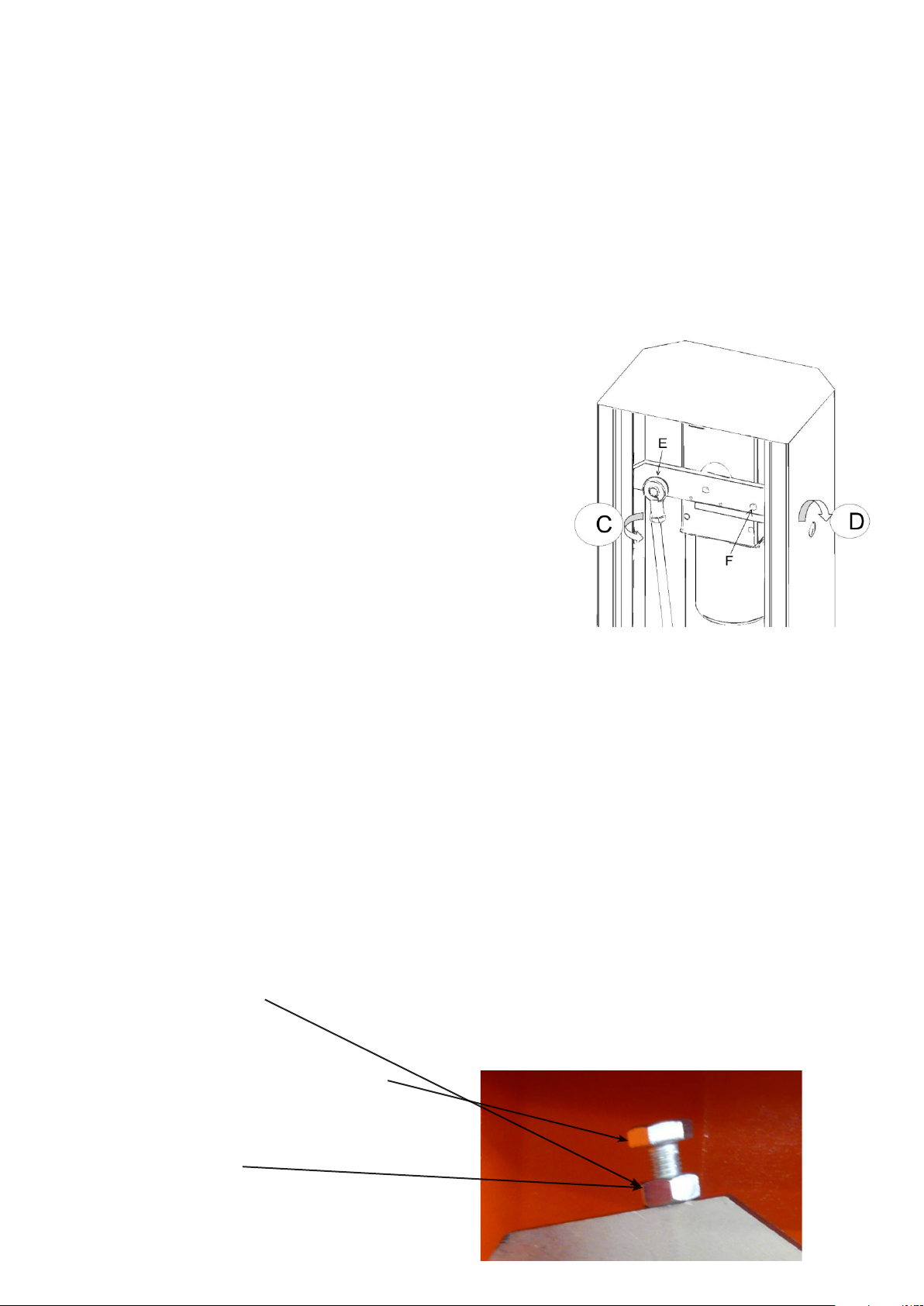
INVERSÃO DO SENTIDO DE ABERTURA
VERSÃO BR4, BR4-24 E BR4-24K
• Desligue a operação de alimentação e manual (ver procedimento de liberação) para trazer a haste na posição vertical, restaurar a transmissão e retirar o corpo para evitar situações de risco.
• Abra a porta, soltar a tensão do sistema de molas (ver gura 2 ref.C) e depois liberá-lo do topo de
xação.
• Retire o parafuso (vide g. Ref.E 2) a m de libertar a mola no topo e permitir a sua colocação no
lado oposto da alavanca de xação (ver gura 2 rif.F).
VERSÃO DA BR-624 E BR-624K
• Desligue a operação de alimentação e manual (veja a Figura 2 ref.D) para trazer a haste na posição vertical, restaurar a transmissão e retirar o corpo para evitar situações de risco.
• Abra a porta, solte o sistema de tensão da mola (veja a Figura 3 ref.C) e solte as molas da
xação superior.
• Retire os parafusos (ver ref Figura 3) de modo a deixar a capota e permitir o seu posicionamento
no lado oposto da alavanca de xação (ver Figura 4 rif.F).
• Solte a alavanca (Fig. 3 rif.G) para permitir a rotação e permitir a montagem das molas no senti-
do oposto (ver Figura 4 rif.H).
• Feche todas as nos locais e esticar as molas (ver balanço).
BALANCEAMENTO
• Desligue a alimentação.
• Desbloqueio da haste (ver Figura 2 ref.D).
• Coloque a haste de cerca de 45 °:
• Solte a porca da mola do tensor s / e.
• Se a barra tende a cair para agir sobre o tensor / primavera e para fazê-lo parar.
• Depois de balanceamento de apertar a porca / i.
• Redenir o poder girando a chave de desbloqueio do motor na direção oposta.
• Restauração de alimentação e vericar se tudo funciona corretamente.
ELIMINAÇÃO
Este produto é composto por vários componentes que, por sua vez, poderão conter
substâncias que poluem. Não jogue no ambiente! Informe-se sobre o sistema de reci-
clagem ou eliminação do produco observando as normas de lei em vigor a nível local.
NÃO ABANDONE NO MEIO-AMBIENTE!
37
PORTUGUÊS
Page 38

SPIS TREŚCI
WAŻNE UWAGI 16
WŁAŚCIWOŚCI TECHNICZNE 17
RODZAJ INSTALACJI 17
WYMIARY ZEWNĘTRZNE 18
INSTALACJA 18
MONTAŻ 19
OTWIERANIE 19
ZASTOSOWANIE RAMIENIA PRZEGUBOWEGO 20
REGULACJA MIKROPRZEŁĄCZNIKA ZATRZYMANIA 20
POŁĄCZENIE ELEKRYCZNE 21
PROGRAMOWANIE 26
BATERIA 28
USUWANIE 28
WAŻNE UWAGI
W razie jakichkolwiek problemów z instalacją, prosimy o skontaktowanie się z Key Automation S.p.A.
TEL. (+48)
Key Automation S.p.A zastrzega sobie prawo do modykowania produktu bez uprzedniego powiadomienia;
odrzuca także wszelką odpowiedzialność za szkody lub okaleczenia wyrządzone osobom ub rzeczom wskutek
niewłaściwego korzystania lub błędnej instalacji.
224.782266
Przeczytaj uważnie niniejszą instrukcję obsługi przed instalacją lub programowaniem układu sterowania.
• Niniejsza instrukcja obsługi skierowana jest wyłącznie do wykwalikowanych techników specjalizujących się w
instalacjach i automatyzacjach.
• Treść niniejszej instrukcji obsługi nie dotyczy użytkownika końcowego.
• Wszelkie czynności programowania i/lub konserwacyjne powinny być wykonywane wyłącznie przez wykwaliko-
wanych techników.
AUTOMATYZACJA MUSI BYĆ WPROWADZANA ZGODNIE Z OBOWIĄZUJĄCYMI PRZEPISAMI EUROPEJSKIMI:
EN 60204-1 (Bezpieczeństwo maszyn, wyposażenie elektryczne maszyn, część 1: Wymagania ogólne)
EN 12445 (Bezpieczeństwo użytkowania zamknięć automatycznych, metody prób)
EN 12453 (Bezpieczeństwo użytkowania zamknięć automatycznych, wymagania)
• Instalator powinien dostarczyć urządzenie (np. wyłącznik magnetotermczny) zapewniające omnipolarne odcięcie sprzętu od zasilania. Standardy wymagają odseparowania styków na co najmniej 3 mm w każdym biegunie (EN 60335-1).
• Plastikowa obudowa posiada izolację IP55; korzystaj z instalacji rur o tym samym poziomie izolacji, aby podłączyć rury elastyczne lub sztywne.
• Instalacja wymaga umiejętności technicznych i mechanicznych, w związku z czym powinna być wykonywana
wyłącznie przez wykwalikowany personel, mogący wydać Certykat Zgdności dotyczący całej instalacji (Dyrekty-
wa maszynowa 2006/42/CEE, Aneks IIA).
• Automatyczne bramy drogowe powinny być zgodne z następującymi normami: EN 13241-1, EN 12453, EN
12445 jak również wszelkimi obowiązującymi przepisami lokalnymi.
• Również instalacja elektryczna, do której podłączana jest automatyka, musi odpowiadać obowiązującym nor-
POLSKI
mom i przepisom i musi być solidnie wykonana.
• Ustawienie siły pchającej skrzydło bramy musi być zmierzone za pomocą odpowiedniego narzędzia i ustawionie
zgodnie z maksymalnymi limitami jakie dopuszcza norma EN 12453.
• Zaleca się wykorzystanie przycisku awaryjnego, zainstalowanego w automatyce (połączonego z wejściem
STOP jednostki sterującej), tak aby brama mogła być natychmiastowo zatrzymana w razie niebezpieczeństwa.
• Z urządzenia nie powinny korzystać dzieci i osoby o ograniczonych zdolnościach zycznych, zmysłowych i umysłowych oraz nieposiadające doświadczenia lub wiedzy, jeśli nie otrzymały odpowiedniego nadzoru lub instrukcji.
• Dzieci będące pod nadzorem nie powinny bawić się urządzeniem.
38
Page 39

MODELE I CHARAKTERYSTYKA 900BR4 900BR4-24 900BR-624 900BR4-24K 900BR-624K
Jednostka sterująca CT-101 CT-24SBA CT-24SBA CT-24SBA CT-24SBA
Zasilanie 230 Vac 24 Vdc 24 Vdc 24 Vdc 24 Vdc
Zasilanie wejściowe 155 W 150 W 150 W 150 W 150 W
Obroty silnika 1400 rpm 1200 rpm 1200 rpm 1200 rpm 1200 rpm
Absorbowanie silnika 0,67 A 6 A 6 A 6 A 6 A
Kondensator 8 µF - - - Czas otwierania 4,5 sek 5 s 10 s 5 s 10 s
Maksymalna długość ramienia 4 m 4 m 6 m 4 m 6 m
Obsługa doraźna 60 % 80 % 80 % 80 % 80 %
TEMPERATURA PRACY -20° +70°C -20° +70°C -20° +70°C -20° +70°C -20° +70°C
Ciężar 35 Kg 35 Kg 43 Kg 35 Kg 43 Kg
RODZAJ INSTALACJI
1
6
5
3
2
3
3
3
4
1 Szlaban
2 Ramię
3 Fotokomórki
4 Słupek fotokomórki
5 Przełącznik wybiórczy sterowany cyfrowo lub kluczykowy
6 Migacz zintegrowany na BRK
39
POLSKI
Page 40

DIMENSIONI D’INGOMBRO
900BR4
900BR4-24
900BR-624
1000
220
320
900BR4-24K
845
8301051
400
280
900BR-624K
POLSKI
1110
220
320
845
1188
830
400
280
40
Page 41

PRZYGOTOWANIE DO AUTOMATYZACJI PODSTAWY
1.
Przygotuj dół fundamentowy oraz kanał na rurę bądź rury kablowe dla okablowania elektrycznego.
2. Zmontuj 4 kotwy podstawy montażowej na płycie montażowej oraz utwierdź je 4 śrubami.
3. Zalej betonem dół fundamentowy i ustaw płytę montażową
UWAGA: sprawdź, czy płyta jest doskonale wypoziomowana i równoległa do szlabanu.
4. Odczekaj do całkowitego związania się cenemtu.
5.
Odkręć 4 nakrętki, które przytrzymują podstawę połączoną z kotwami podstawy i ustaw ramę na płycie.
Płyta Tylna-BR
Płyta Tylna-BR6
41
POLSKI
Page 42

MONTAŻ
Otwórz opakowanie i sprawdź stan wszystkich części urządzenia.
Wykonaj wylewkę w zbrojonym cemencie i zatop kotwy podstawy z trzpieniami (opcjonalnie) z dostarczonymi przymoco-
wanymi nakrętkami.
Sprawdź, czy jest doskonale wypoziomowana i czy kanał
dla okablowania osłania krzyżowo centralny otwór na płycie
montażowej.
Ustaw szlaban i sprawdź, czy ramię szlabanu nie napotka
żadnych przeszkód na drodze swojego ruchu.
UWAGA: nigdy nie poruszaj ramieniem szlabanu, kiedy
jest ono w pozycji poziomej oraz nie podejmuj się żadnych działań i manipulacji, gdy ramię nie jest zamocowane.
ZAMKNIĘCIE
Jeżeli ramię ma być poruszane ręcznie, postępuj według wskazówek:
• Odetnij dopływ prądu.
• Włóż dostarczony klucz zwalniający i zdejmij zasuwę, następnie umieść klucz do wkrętów z
sześciokątnym gniazdkiem, po czym przekręć go o 90° (zobacz rys. 2 ref. D).
• Tym sposobem możesz odłączyć wewnętrzny zespół zwalniający w celu awaryjnej manipu-
lacji.
• Wykonaj ręczną manipulację.
• By włączyć napęd przekręć klucz do wkrętów z sześciokątnym gniazdkiem do pierwotnej
pozycji, po czym zablokuj zamek.
• Możesz teraz przywrócić zasilanie i sprawdzić, czy wszystko działa poprawnie.
WYRÓWNANIE KĄTA RAMIENIA
Jeżeli potrzebujesz wyrównać uchwyt mocowania ramienia, postępuj wedle wskazówek:
• Zwolnij nakrętkę zabezpieczającą (umieszczoneą na obudowie w przypadku modeli BR-V,
BR4-24 and BR4-24K, bądź na wahaczu w przypadku BR-624 and BR-624K).
• Ustaw śrubę na pożądanej wysokości.
• Zabezpiecz nakrętkę w pierwotnym miejscu.
Poluzuj mocującą nakrętkę
POLSKI
Ustaw śrubę na pożądanej wysokości.
Utwierdź mocującą nakrętkę w
odpowiednim miejscu.
42
Page 43

ODWRÓCENIE KIERUNKU OTWIERANIA I WYWAŻENIE
Wersja BR-V, BR4-24 i BR4-24K
• Wyłącz zasilanie i za pomocą ręcznej manipulacji, umieść ramię pionowo, przywróć napęd i
wyjmij ramię, aby zapobiec niebezpiecznym warunkom.
• Otwórz drzwiczki, poluźnij napięcię systemu sprężynowania, następnie zwolnij go z górnego
mocowania.
• Odkręć śrubę mocującą, tak by górną część sprężynowania można było ustawić odwrotnie
wobec mocującej dźwigni.
Wersja BR-624 i BR-624K
• Wyłącz zasilanie i za pomocą ręcznej manipulacji, umieść ramię pionowo, przywróć napęd i
wyjmij ramię, aby zapobiec niebezpiecznym warunkom.
• Otwórz drzwiczki, poluźnij napięcię systemu sprężynowania, następnie zwolnij go z górnego
mocowania.
• Odkręć śrubę mocującą, tak by górną część sprężynowania można było ustawić odwrotnie
wobec mocującej dźwigni.
• Odkręć dźwignię, tak by można było ją obracać i umożliwić mocowanie sprężyn w odwrot-
nym kierunku.
• Przymocuj wszystko wedle wspomnianego położenia i napnij sprężyny (zobacz akapit o
wyrównaniu).
WYRÓWNANIE
• Odetnij dopływ prądu.
• Zwolnij ramię.
• Umieść ramię pod kątem ok. 45°.
• Zwolnij nakrętkę, bądź nakrętki zabezpieczające napinacza, bądź napinaczy sprężyn.
• Jeżeli ramię opada, wyreguluj napinacz(e) sprężyn tak by ramię zatrzymało się.
• Kiedy wyrównanie jest ukończone, utwierdź nakrętkę, lub nakrętki mocujące.
• Przywróć funkcjonowanie napędu poprzez przekręcenie klucza zwalniającego w odwrotnym
kierunku.
• Przywróć zasilanie i sprawdź czy wszystko działa poprawnie.
LIKWIDACJA
Niniejszy produkt składa się z różnych komponentów, które z kolei mogą zawierać substancje zanieczyszczające. Nie likwiduj go w środowisku! Znajdź metodę utylizacji lub
likwidacji produktu zgodną z obowiązującymi lokalnie przepisami.
43
POLSKI
Page 44

NOTE ANMERKUNGEN
NOTES NOTA
NOTES OBSERVAÇÕES
Page 45

NOTE ANMERKUNGEN
NOTES NOTA
NOTES OBSERVAÇÕES
Page 46

CERTIFICATO DI GARANZIA
(In riferimento all’articolo 1519 bis ss. cc..)
Key Automation si congratula con Lei per la scelta effettuata, al ne
di avere una durata massima dell’impianto Le ricordiamo di utilizzare
solamente accessori, ricambi e componenti Key Automation.
Il presente certicato dovrà essere letto accuratamente, compilato in
tutte le sue parti e conservato pena l’annullamento della garanzia.
La garanzia decorre dalla data di acquisto/installazione dell’impianto
ed ha validità 24 mesi.
Ricordiamo all’utente che per attivare la garanzia è necessario rispedire il tagliando relativo all’azienda costruttrice a mezzo raccoman-
data presso:
Key Automation S.p.A.
Via A.Volta, 30
30020 Noventa di Piave (VE)
Key Automation garantisce che i suoi prodotti sono esenti da difetti
di produzione e sono stati sottoposti a test di qualità e funzionalità.
Il giudizio sull’applicabilità della garanzia è delegato al servizio tecnico di Key Automation ed è insindacabile.
La garanzia perde di validità qualora:
• Siano passati i termini previsti di 24 mesi dalla data di acquisto/
installazione;
• Installazione e/o uso non conforme alle istruzioni;
• Manomissioni, negligenza o danni da trasporto;
• Manutenzione non conforme o effettuata da personale non
autorizzato;
• Sia evidente che il prodotto è stato alterato o smontato senza
assistenza tecnica;
• Fenomeni naturali, dolo o traumi esterni non imputabili a Key
Automation;
• Mancata presentazione di tagliando di garanzia e/o scontrino/
fattura scale;
• Mancata compilazione e spedizione del tagliando allegato.
Key Automation declina ogni responsabilità per eventuali danni diretti od indiretti a cose, persone o animali derivanti dalla inosservanza
di tutte o parti delle prescrizioni ed istruzioni allegate al prodotto e
alla mancata osservanza delle direttive di installazioni vigenti.
Ricordiamo inoltre al cliente di conservare lo scontrino o la ricevuta
scale per poterlo esibire ogni qualvolta si renda necessario un
intervento tecnico.
Qualora il cliente desiderasse contattare il centro assistenza più vicino potrà visitare il nostro sito www.keyautomation.it, dove troverà
indirizzi e numeri di telefono utili.
GUARANTEE CERTIFICATE
Key Automation congratulates with you for the excellent choice. We
would like to remind our customers that in order to obtain the maximum operation of the system it is necessary to use only accessories,
spare parts and components sold by Key Automation.
This certicate should be read carefully, lled in all its parts and
preserved to avoid the guarantee to become invalid.
The guarantee takes effect from the date of purchase/installation of
the system and it lasts for 24 months. We remind users that products
will be covered by guarantee only if the coupon concerning the pro-
ducing company is sent back through certied mail to:
Key Automation S.p.A.
Via A.Volta, 30
30020 Noventa di Piave (VE)
Key Automation ensures that its products are awless and that they
underwent quality and functionality tests. Key Automation technical
service will decide whether the guarantee is to be applied and its
judgement will be incontrovertible.
The guarantee is no longer valid in the following cases:
• Products sent back after more than 24 months from pur-
chase/installation;
• Installation/use not in compliance with given instructions;
• Disregard, inappropriate repair or damage caused during
transport;
• Repairs carried out by not authorized personnel or inad-
equate;
• It is clear that the product was damaged and disassembled
without technical assistance;
• Natural phenomena, fraud or external causes for which Key
Automation is not responsible;
• The guarantee coupon and/or the receipt/invoice has not
been preserved;
• The enclosed coupon has not been lled in and sent it back.
Key Automation declines every responsability for possible direct
or indirect damage to things, people or animals caused by the
non-compliance of all or some of the prescriptions and instructions
enclosed to the product and by the lack of compliance with directives
of installations in force.
We would also remind customers to preserve the receipt or invoice
in order to be able to submit it, if technical interventions are needed.
In our web site www.keyautomation.it, customers can nd useful
addresses and telephone numbers, in case they need to contact
their nears centre of assistance.
TIMBRO RIVENDITORE - RETAILER’S STAMP
TAGLIANDO DI GARANZIA - GUARANTEE COUPON
DATI APPARECCHIO - TECHNICAL DATA OF DEVICE:
MODELLO - MODEL:
N° MATRICOLA - NUMBER:
DATA ACQUISTO - PURCHASING DATE:
DATA INSTALLAZIONE - INSTALLATION DATE:
DATI DELL’UTILIZZATORE / USER’S DETAILS:
COGNOME/NOME - SURNAME/NAME :
VIA - STREET . N°
CAP - POST CODE CITTÀ - CITY/TOWN
PROV TEL
LUOGO INSTALLAZIONE - INSTALLATION SITE
DATI DELL’INSTALLATORE - DETAIL OF THE INSTALLING COMPANY :
COGNOME / RAG.SOCIALE - SURNAME / NAME OF THE COMPANY
VIA - STREET N°
CAP - POST CODE CITTÀ - CITY/TOWN
PROV TEL FAX
P.IVA - VAT NUMBER
Firma installatore per accettazione delle clausole, condizioni generali di garanzia e trattamento dati
personali, (legge 675 del 31/12/1996), l’installatore dichiara inoltre di aver compilato la garanzia
impianto per quanto di propria competenza e responsabilità.
FIRMA IN ORIGINALE
ORIGINAL SIGNATURE
TIMBRO INSTALLATORE - STAMP OF THE INSTALLING COMPANY:
Page 47

DICHIARAZIONE “CE” DI CONFORMITÀ
Il costruttore: Key Automation S.p.A
The manufacturer:
Indirizzo: Via Alessandro Volta, 30 Noventa di Piave (Ve)
Address:
DICHIARA CHE IL SEGUENTE APPARATO
DECLARES THAT THE FOLLOWING EQUIPMENT
Descrizione: Automazione per barriere stradali
Description: Automation for street barriers
Modello: ALT 4
Model:
ALT 6
ALT 4K
ALT 6K
Codice: 900BR4
Code:
900BR-624
900BR4-24K
900BR-624K
900BR4-24
Risulta conforme a quanto previsto dalle seguenti direttive comunitarie:
Appears to be in conformity with the following community (EC) regulations:
Direttiva macchine / Machinery Directive 2006/42/EC
Direttiva bassa tensione / Low Voltage Directive 2006/95/EC
Direttiva compatibilità elettromagnetica / EMC Directive 2004/108/EC
Risulta conforme a quanto previsto dalle seguenti norme armonizzate:
Appears to be in conformity with the following harmonized standards regulations:
EN 55014-1 + EN 55014-2
EN 61000-3-2 + EN 61000-3-3
EN 60335-1 + EN 60335-2
EN 55022
Nota: Dichiara che non è consentito mettere in servizio i dispositivi sopra elencati no a che la macchina (barriera automatizzata) sia stata identicata, marchiata CE e ne sia stata emessa la conformità alle condizioni della Direttiva 89/392/
EEC e successive modiche.
Note: Declares that the above mentioned devices may not be operated until the machine (automated barrier) is identied,
CE labeled, and declared to be compliant to the specications of Directive 89/392/EEC and following modications.
Il responsabile della messa in servizio deve fornire i seguenti documenti: Fascicolo tecnico + Dichiarazione di conformità
+ Marcatura CE + Verbale di collaudo + Registro della manutenzione + Manuale di istruzioni ed avvertenze
The person in charge for the machine start-up must provide the following records: Technical specication paper + Declaration of conformity + CE-labeling + Testing record + Maintenance record + Operation manual and directions
Noventa di Piave 07/01/2009 Il Rappresentante legale
The legal Representative
Nicola Michelin
Page 48

Key Automation S.p.A
Società con unico socio
Via Alessandro Volta, 30
30020 Noventa di Piave (Ve) Italia
T. +39 0421.307.456
F. +39 0421.656.98
info@keyautomation.it
KEY - POLSKA SP. Z.O.O.
ul. Gierdziejewskiego 7
Wejscie IV, LOK 12
Warszawa 02-495 - Polska
T. +48 224.782266
F. +48 224.782267
info@key-polska.pl
www.key-polska.pl
KEY AUTOMATION (HANGZHOU) CO., LTD
No. 385, Road No.18,
Economic & Technology Development Zone,
Hangzhou, P.R.China - P.C. 310018
T. +86 571.86703900
F. +86 571.86703901
P.IVA 03627650264 C.F. 03627650264
Capitale Sociale Euro 400.000,00 i.v.
Reg. Imprese di Venezia n. 03627650264
REA VE326953
www.keyautomation.it
580ISBR rev02Дэнис ®
 Loading...