

Page 1
Montageanleitung Laufband
A
TRAVELLER Art.-Nr. 7885-000
D
GB
F
NL
E
Der Umwelt zuliebe: wir drucken auf 100% Altpapierl
I
PL
bb. Ahnlich, Zubehor optional
1
11
Page 2

g
Bitte lesen Sie diese Anleitung vor der Montage und der ersten Benutzung aufmerksam durch. Sie erhalten
wichtige Hinweise für Ihre Sicherheit sowie den Gebrauch und die Wartung des Laufbandes . Bewahren Sie diese
Anleitung zur Information bzw. für Wartungsarbeiten oder Ersatzteilbestellungen sorgfältig auf.
Alle KETTLER-Produkte werden nach dem aktuellen Stand der Sicherheitsvorschriften konstruiert und unter einer
ständigen Qualitätsüberwachung gefertigt. Die hieraus gewonnenen Erkenntnisse lassen wir in unsere Entwicklung
einfließen. Aus diesem Grunde behalten wir uns Änderungen in Technik und Design vor, um unseren Kunden immer eine
optimale Produktqualität bieten zu können. Sollte es trotzdem Grund für Beanstandungen geben, wenden Sie sich bitte
an Ihren Fachhändler.
Zu Ihrer Sicherheit
✿ Das Laufband darf nur für seinen bestimmungsgemäßen
Zweck verwendet werden, d. h. für das Lauf- und
Gehtraining erwachsener Personen.
✿ Das Gerät ist nicht für die gewerbliche Nutzung
vorgesehen. Jegliche andere Verwendung ist unzulässig
und möglicherweise gefährlich. Der Hersteller kann nicht
für Schäden verantwortlich gemacht werden, die durch
einen nicht bestimmungsgemäßen Gebrauch verursacht
wurden.
✿ Beschädigte Bauteile können Ihre Sicherheit und die
Lebensdauer des Gerätes beeinträchtigen. Entziehen Sie
deshalb das Gerät bis zur Instandsetzung der Benutzung
und verwenden Sie im Bedarfsfall nur Original KETTLERErsatzteile.
✿ Das Laufband entspricht den vorgeschriebenen
Sicherheitsbestimmungen. Durch unsachgemäße
Reparaturen und bauliche Veränderungen (Demontage von
Originalteilen, Anbau von nicht zulässigen Teilen, usw.)
können Gefahren für den Benutzer entstehen.
✿ Das Laufband muß auf einem festen, ebenen
Untergrund aufgestellt werden. Achten Sie unbedingt
darauf, daß das Elektrokabel nicht eingeklemmt oder zur
„Stolperfalle” wird.
✿ Achten Sie auch darauf, daß der Raum unter dem
Laufband freigehalten wird und sich niemals z. B.
Gegenstände oder Haustiere unter dem Gerät
befinden!
✿ Fassen Sie unter gar keinen Umständen mit den Händen
an das sich bewegende Endlosband. Auch dürfen sich
keine Gegenstände in der Nähe des Bandes oder der
Laufrollen befinden, die eingezogen werden könnten.
Verletzungsgefahr oder Beschädigung des
Laufbandes!
✿ Das Laufband ist nicht für Personen mit einem
Körpergewicht von mehr als 120kg geeignet.
✿ Bei der Aufstellung des Gerätes ist ein
Sicherheitsbereich von je 1m zur Seite und 2m nach hinten
zu wahren.
✿ Das Gerät benötigt eine Netzspannung von 220-230 V,
50 Hz. Der Anschluß darf nur an einer mit 16 A einzeln
abgesicherten und geerdeten Schukosteckdose erfolgen.
Nehmen Sie niemals Eingriffe an Ihrem Stromnetz
selber vor, beauftragen Sie ggf. qualifiziertes
Fachpersonal!
✿ Verwenden Sie keine Mehrfachsteckdosen zum
Anschluß! Bei Verwendung eines Verlängerungskabels
muß dieses den VDERichtlinien entsprechen.
✿ Ziehen Sie nach Gebrauch immer den Netzstecker des
Gerätes aus der Steckdose.
✿ Bei Reinigungs- und Wartungsarbeiten muß das
Gerät unbedingt spannungsfrei geschaltet werden
(Netzstecker ziehen)!
✿ Es ist darauf zu achten, dass niemals Flüssigkeit in
das Geräteinnere gelangt! Dies gilt auch für
Körperschweiß.
✿ Reparaturen an elektrischen Teilen und Baugruppen
dürfen nur von qualifiziertem Fachpersonal durchgeführt
werden!
✿ Beachten Sie weiterhin die allgemeinen
Sicherheitsbestimmungen und-vorkehrungen für den
Umgang mit elektrischen Geräten.
✿ Beachten Sie auch unbedingt die Hinweise zur
Trainingsgestaltung in der Trainingsanleitung!
✿ Das KETTLER Laufband verfügt zu Ihrer Sicherheit über
eine Not-Stop-Vorrichtung. Befestigen Sie vor
Trainingsbeginn die Schnur des Sicherheitsschlüssels
an Ihrer Kleidung. Falls das Laufband durch Abziehen
des Sicherheitsschlüssels ausgeschaltet wurde,
stecken Sie ihn wieder auf. Ein automatischer
Wiederanlauf des Endlosbandes findet nicht statt.
Weitere Hinweise zur Handhabung der
Sicherheitsabschaltung finden Sie in der
Bedienungsanleitung des Computers.
✿ Eine unkontrollierte Benutzung des Laufbandes durch
Dritte kann durch Abziehen und Verwahrung des
Sicherheitsschlüssels vermieden werden.
✿ Im Notfall halten Sie sich mit beiden Händen an den
Handläufen fest, und verlassen das Band auf die seitlichen
Flächen der Seitenplattformen. Betätigen sie die Not-StopVorrichtung (Sicherheitsabschaltung).
✿ Alle elektrischen Geräte senden beim Betrieb
elektromagnetische Strahlung aus. Achten Sie darauf,
besonders strahlungsintensive Geräte (z. B. Handys) nicht
in direkter Nähe des Cockpits oder der
Steuerungselektronik abzustellen, da sonst Anzeigewerte
verfälscht werden könnten (z. B. Pulsmessung).
✿ Alle hier nicht beschriebenen Eingriffe /
Manipulationen am Gerät können eine Beschädigung
hervorrufen oder auch eine Gefährdung der Person
bedeuten. Weitergehende Eingriffe sind nur vom
KETTLER-Service oder von KETTLER geschultem
Fachpersonal zulässig.
✿ Um das konstruktiv vorgegebene Sicherheitsniveau
dieses Gerätes langfristig garantieren zu können, sollte das
Gerät regelmäßig vom Spezialisten (Fachhandel) geprüft
und gewartet werden (einmal im Jahr).
✿ Bei Fragen wenden Sie sich bitte an Ihren Fachhändler.
Zur Handhabung
✿ Normen:
Das Gerät entspricht der DIN EN 957-1/6, Klasse HC. Es
ist dementsprechend nicht für den therapeutischen Einsatz
geeignet.
✿ Stellen Sie sicher, daß der Trainingsbetrieb nicht vor der
ordnungsgemäßen Ausführung und Überprüfung der
Montage aufgenommen wird.
✿ Eine Verwendung des Gerätes in Feuchträumen nicht
gestattet. Achten Sie auch darauf, dass keine
Flüssigkeiten (Getränke, Schweiß, usw.) auf Teile des
2
Gerätes gelangen. Dies könnte zu Korrosionen führen.
✿ Das Laufband ist als Trainingsgerät für Erwachsene
konzipiert und keinesfalls als Kinderspielgerät geeignet.
Bedenken Sie, daß durch das natürliche Spielbedürfnis und
Temperament von Kindern oft unvorhergesehene
Situationen entstehen können. Falls Sie dennoch Kinder an
ein Laufband lassen, unterweisen Sie sie in der richtigen
Benutzung des Gerätes und beaufsichtigen Sie sie.
✿ Tragen Sie bei der Benutzung des Laufbands
geeignetes
Schuhwerk (Sportschuhe).
22
Page 3

Wichtige Hinweise
✿ Machen Sie sich vor dem ersten Training auf dem
Laufband mit allen Funktionen und Einstellmöglichkeiten
des Gerätes vertraut.
✿ Führen Sie bei regelmäßigem Trainingsbetrieb in
angemessenen Abständen Kontrollen aller Geräteteile,
insbesondere der Schrauben durch.
✿ Zwischen Bodenbrett und Laufband ist werksseitig ein
Gleitmittel aufgetragen. Je nach Häufigkeit der Benutzung
muß dieses erneuert werden. Benutzen Sie dafür das
beiliegende hochwertige Silikonöl (siehe Wartungshinweis).
✿ Beobachten Sie beim Betrieb die Kantenbewegung des
Laufbandes; weicht das Band seitlich ab, so ist eine
Nachjustierung erforderlich (siehe “Handhabung”).
Zur Pflege und Wartung
✿ Verwenden Sie zur Säuberung und Pflege
umweltfreundliche, keinesfalls aggressive oder ätzende
Mittel.
✿ Die elektrischen Teile und Baugruppen des Laufbandes
sind wartungsarm. Es besteht keine Veranlassung, in
diesen Teil des Gerätes einzugreifen. Ausgenommen sind
Reparaturen oder Wartungschecks durch qualifiziertes
Fachpersonal.
✿ Für Ersatzteilbestellungen benutzen Sie bitte die
Ersatzteilstückliste. Geben Sie bei Ersatzteilbestellungen
bitte immer die vollständige Artikelnummer, die
Ersatzteilbestellnummer, die benötigte Stückzahl sowie die
Seriennummer des Gerätes an.
✿ Je nach Beanspruchung und Belastung kann sich das
Endlosband mit der Zeit u. U. etwas längen und
„durchrutschen”. Korrigieren Sie die Bandstraffung wie in
„Handhabung“ beschrieben.
Lauftipp:
durch Fokussierung auf einen fest stehenden Gegenstand
vor Ihnen im Raum erleichtert. Laufen Sie, als ob Sie auf
das Objekt zugehen wollten.
Wichtig:
sorgfältig auf und verhindern, dass Kinder an den
Sicherheitsschalter gelangen!
Bestellbeispiel: „Artikelnummer 7885-000/ Ersatzteilnr.
68001000 / 1 Stück / Seriennummer ...“
Wichtig: Zu verschraubende Ersatzteile werden
grundsätzlich ohne Verschraubungsmaterial berechnet und
geliefert. Falls Bedarf an entsprechendem
Verschraubungsmaterial besteht, ist diese durch den
Zusatz „mit Verschraubungsmaterial“ bei der
Ersatzteilbestellung anzugeben. Falls Sie nur das
komplette Verschraubungsmaterial benötigen, bestellen Sie
bitte Pos. 90 mit entsprechender Ersatzteilnummer.
Ein gerades Laufen auf dem Laufband wird
Bitte bewahren Sie den Sicherheitsschalter
Montagehinweise
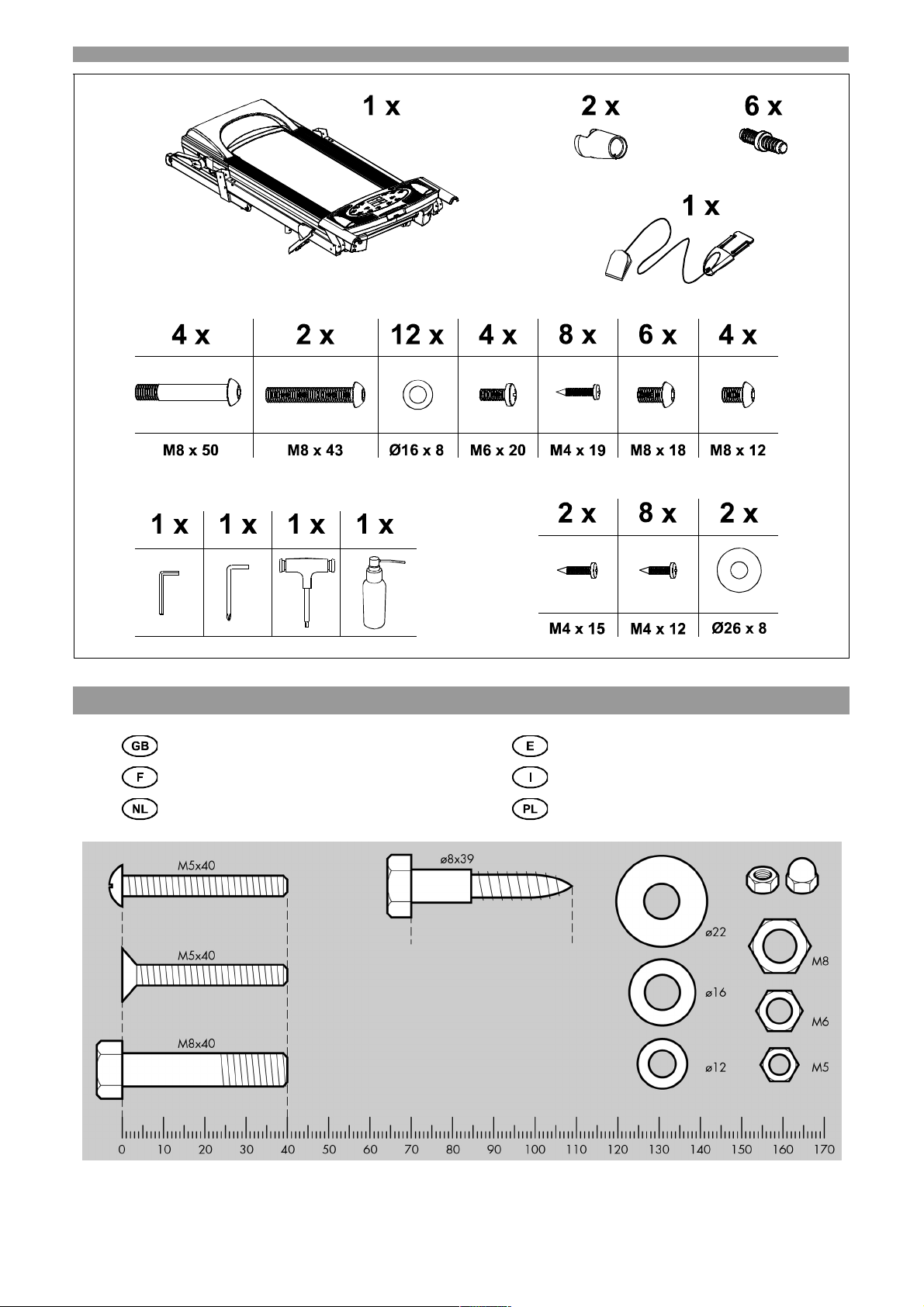
✿ Bitte prüfen Sie, ob alle zum Lieferumfang gehörenden
Teile vorhanden sind (s. Checkliste) und ob
Transportschäden vorliegen. Sollte es Anlaß für
Beanstandungen geben, wenden Sie sich bitte an Ihren
Fachhändler.
✿ Sehen Sie sich die Zeichnungen in Ruhe an, und
montieren Sie das Gerät entsprechend der Bilderfolge.
Innerhalb der einzelnen Abbildungen ist der Montageablauf
durch Großbuchstaben vorgegeben.
✿ Beachten Sie, dass bei jeder Benutzung von Werkzeug
und bei handwerklichen Tätigkeiten immer eine mögliche
Verletzungsgefahr besteht. Gehen Sie daher sorgfältig und
umsichtig bei der Montage des Gerätes vor!
✿ Sorgen Sie für eine gefahrenfreie Arbeitsumgebung,
lassen Sie z. B. kein Werkzeug umherliegen. Deponieren
Sie z. B. Verpackungsmaterial so, dass keine Gefahren
davon ausgehen kann. Bei Folien/Kunststofftüten für Kinder
Erstickungsgefahr!
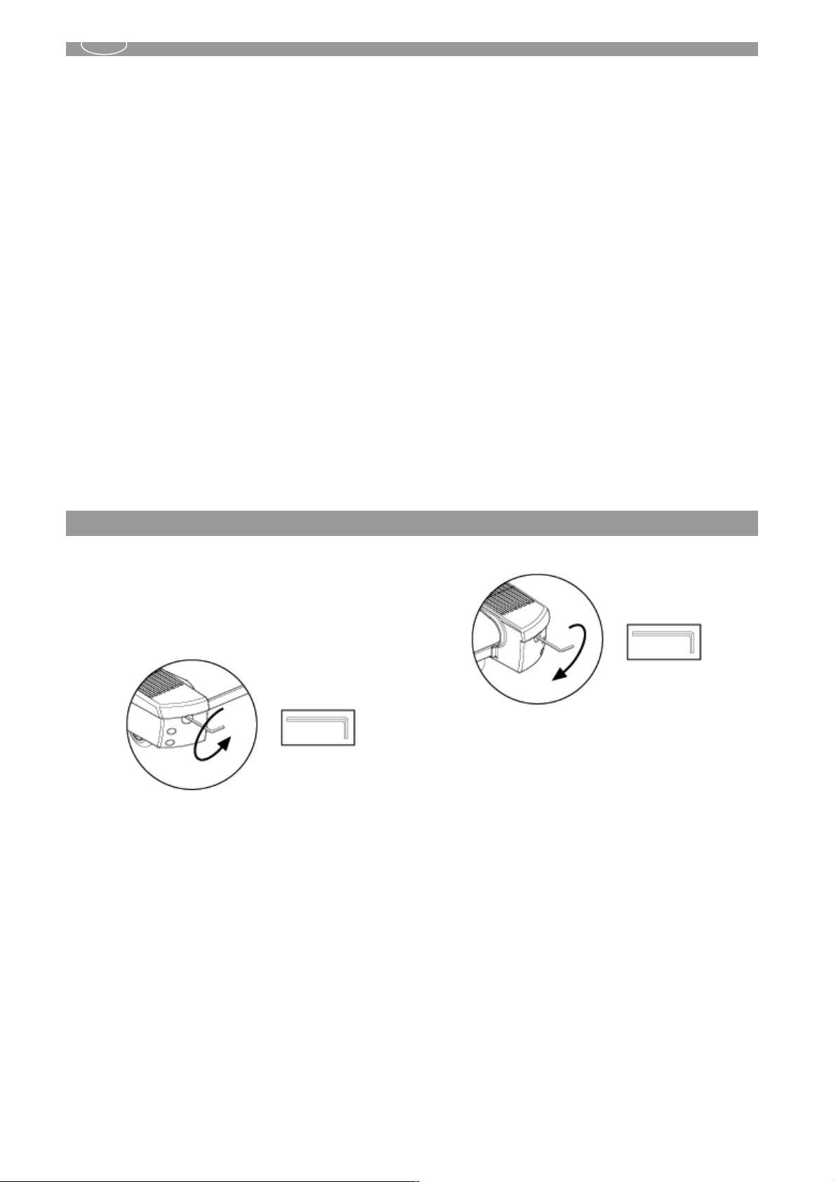
Handhabung
Bandjustierung:
Der Bandlauf wurde werksseitig justiert. Durch
verschiedene Einflüsse, wie z. B. Transport, kann jedoch
eine Nachjustierung oder -straffung des Laufbandes nötig
werden. Ziehen Sie dabei immer den Netzstecker aus der
Steckdose!
Wandert das Band nach rechts, drehen Sie die rechte
Stellschraube mit dem beiliegenden Steckschlüssel um
maximal eine Viertel Umdrehung im Uhrzeigersinn.
Stecken Sie das Netzkabel wieder ein und lassen Sie das
Band bei 4 km/h laufen. Das Band sollte sich nun selbst in
eine zentrierte Position korrigieren. Ist dies nicht der Fall,
wiederholen Sie den Vorgang solange, bis das Band wieder
gerade läuft.
Weicht das Band nach links ab, drehen Sie die linke
Stellschraube mit dem beiliegenden Steckschlüssel um
maximal eine Viertel Umdrehung im Uhrzeigersinn.
Stecken Sie das Netzkabel wieder ein und lassen Sie das
Band bei 4 km/h laufen. Das Band sollte sich nun selbst in
eine zentrierte Position korrigieren. Ist dies nicht der Fall,
✿ Die Montage des Gerätes muß sorgfältig und von einer
erwachsenen Person vorgenommen werden. Nehmen Sie
im Zweifelsfall die Hilfe einer weiteren, technisch begabten
Person in Anspruch.
✿ Das für einen Montageschritt notwendige
Verschraubungsmaterial ist in der dazugehörigen Bildleiste
dargestellt. Setzen Sie das Verschraubungsmaterial exakt
entsprechend der Abbildungen ein. Alles erforderliche
Werkzeug finden Sie im Kleinteilebeutel.
✿ Bitte verschrauben Sie zunächst alle Teile lose und
kontrollieren Sie deren richtigen Sitz. Anschließend ziehen
Sie sie mit einem Schraubenschlüssel richtig fest.
✿ Bewahren Sie die Originalverpackung des Gerätes gut
auf, damit sie später u. U. als Transportverpackung
verwendet warden kann.
✿ Aus fertigungstechnischen Gründen behalten wir uns die
Vormontage von Bauteilen (z.B. Rohrstopfen) vor.
wiederholen Sie den Vorgang solange, bis das Band wieder
gerade läuft.
Nach der Bandjustierung kann u. U. eine Bandstraffung
nötig sein, falls das Band durchrutschen sollte.
Bandstraffung:
Ziehen Sie auch hierzu als erstes den Netzstecker aus der
Steckdose. Drehen Sie die rechte und die linke
Stellschraube eine Viertel Umdrehung im Uhrzeigersinn.
Stecken Sie das Netzkabel wieder ein und lassen Sie das
Band bei 4 km/h laufen. Kontrollieren Sie, ob das
Endlosband beim Begehen durchrutscht. Ist dies der Fall,
müssen Sie den beschriebenen Vorgang noch einmal
durchführen.
Gehen Sie bei der Bandjustierung und -straffung sehr
sorgfältig vor; eine extreme Über- oder Unterspannung
kann zu Schäden am Laufband führen!
Das Band sollte so gespannt werden, dass es gerade nicht
durchrutscht.
33
3
Page 4

y
All KETTLER products are designed in accordance with the latest safety regulations and undergo a constant
process of quality control during manufacturing. The knowledge gained in this process is used to constantly
imporve and develop our products. In order to offer our customers the very best in product quality, we reserve
the right to make technical changes at any time. In spite of this, should you have any cause for complaint,
please contact your KETTLER dealer.
For Your Safety
The running belt should be used only for its intended
purpose, i.e. for physical exercise (walking and
jogging) by one (1) adult persons.
The running belt is not suitable for commercial use.
Any other use of the equipment is prohibited and may
be dangerous. The manufacturer cannnot be held
liable for damage or injury caused by imporper use of
the equipment.
Damaged components may endanger your safety or
reduce the lifetime of the equipment. For this reason,
worn or damaged parts should be replaced
immediately and the equipment taken out of use until
this has been done. Use only original KETTLER spare
parts.
The running belt has been designed in accordance
with the latest standards of safety. Incorrect repairs
and structural modifications (e.g. removal or
replacement of original parts) may endanger the safety
of the user.
The running belt must be set up on firm even ground.
Ensure that the power cable is not pinched and that
no-one can trip over it.
Always ensure that the space under the running
belt is kept free, i.e. that there are no objects, pets
etc. beneath it.
Never touch the moving belt with your hands. Also
ensure that there are no objects close to the belt or the
rollers which could be pulled into it thus causing
injury or damaging the unit itself.
The running belt is not suitable for use by persons
weighing over 120kg.
The unit should be positioned in such a way that there
is a space of 100cm on both side and 200cm behind it.
The unit requires a power supply of 220-230V / 50Hz.
It should be connected only to an earthed safety
socket with a single 16-A fuse. Do not under any
circumstances carry out electrial repairs or
alterations yourself. Always ensure that such
work is done by a proberly qualified electrician.
Do not use a multiple power socket for the running
belt. If an extension cable is being used, ensure that it
complies with the VDE regulations.
When the unit is not in use, unplug it from the power
supply.
Handeling the equipment
Standards:
The machine complies with the DIN EN 957-1/6, class
HC. It is therefore unsuitable for therapeutic use.
Before using the equipment for exercise, check
carefully to ensure that it has been correctly
assembled and checked.
Usage of the equipment in damp rooms is not
permitted. Please ensure that no part of the machine
comes in contact with liquid (drinks, perspiration etc.).
This may cause corrosion.
The running belt is designed for use by adults and
children should not be allowed to play with it. Children
at play behave unpredictalby and dangerous situations
may occur for which the manufacturer cannnot be held
liable. If, in spite of this, children are allowed to use
the equipment, ensure that they are instructed in its
proper use and are supervised accordingly.
To ensure that the safety level is kept to the highest
possible standard, determined by its construction, this
product should be serviced regulary (once a year) by
specialist retailers.
Before carrying out cleaning or maintenance work,
always disconnect the running belt from the power
supply (i.e. pull the plug out of the socket).
Please ensure that liquids or perspiration never
enter the machine or electronics.
Repairs on the electrical components in the unit should
be carried out by qualified persons only.
Always observe the general safety rules and
precautions for working with electrical equipment.
All electric applicances emit electromagnetic radiation
when in operation. Please do not leave especially
radiation-intensive appliances (e.g. mobile telephones)
directly next to the cockpit or the electronic
controlsystem as otherwise values displayed might be
distorted (e.g. pulse measurement).
Prior to training attach the cord of the running belt
stop trip to your clothing.
The KETTLER treadmill has an emergenty stop
mechanism for your safety. Before starting your
workout, fasten the cord of the safety key to your
clothing. If the treadmill has been shut down by
removing the safety key, restart it by reinserting
the key. An automatic restart of the treadmill belt
does not occur. Further instructions concerning the
handleing fo the safty cut-out can be found in the
operating instrucitons for the training computer.
An unmonitered use of the treadmill by other people
can be prevented by removing the safety key and
keeping it safely hidden.
In case of any emergency, hold on tightly to the
handrail with both hands and leave the treadmill by
means of the antislipping surface of the lateral
platofrm. Activate the emergence stop mechanism
(safety cut-out).
Any interface with parts of the product that are not
described within the manual may cause damage,
or endanger the person using this machine.
Extensive repairs must only be carried out by
KETTLER service staff or qualified personnel
trained by KETTLER.
Should you be in any doubt, please consult your
dealer.
Always wear suitable shoes (running shoes) when
using the running belt.
Before beginning your first training session, familiarize
yourself throughly with all the functions and settings of
the unit.
If the equipment is in regular use, check all its
components throughly at appropriate intervals. Pay
particular attention to the tightness of bolts and nuts.
In case of a regular use of the running belt, the cold
running belt has to be serviced with silicone oil.
Depending on the degree of use and load to which the
unit is subjected, the belt may tend to stretch or slip.
Tighten the belt as described. Adjust the tightness of
the belt as describe in section „handeling“.
Observer the movement of the edge of the belt when it
is in use. If it tends to run towards the side, readjust it
accordingly.
4
44
Page 5
Assembly Instructions
Running Tip: Running straight on the treadmill is made
GB
easier by focussin on a fixed oject in front of you in the
room. Rus as if you wanted to approach the object.
Importantly: Please keep the safety key in a safe place
and ensure that it is kept out of reach of children!
Care and Maintenance
Do no use corrosive or abrasive materials to clean the
equipment. Ensure that such materials are not
allowed to pollute the environment.
The electrical elements and components do not
require special maintenance. No alterations or repairs
(except maintenance checks) should be made to these
parts unless by a qualified electrician.
When ordering spare parts, always state the full article
Instructions for Assembly
Ensure that you have received all the parts required
(see check list) and that they are undamaged. Should
you have any cause for complaint, please contact your
KETTLER dealer.
Before assembling the equipment, study the drawings
carefully and carry out the operations in the order
shown by the diagrams. The correct sequence is
given in capital letters.
The equipment must be assembled with due care by
an adult person. If in doubt call upon the help of a
second person, if possible technically talented.
Please note that there is always a danger of injury
when working with tools or doing manual work.
Therefore please be careful when assembling this
machine.
Ensure that your working area is free of possible sources of
Handling
number, spare-part number, the quantity required and the
serial number of the product.
Example order: item no. 7885-000 / spare-part no.
68001000 / 1 pieces /serial no......
Important: spare part prices do not include fastening
material; if fastening material (bolts, nuts, washers etc.) is
required, this should be clearly stated on the order by
adding the words „with fastening material“.
danger, for example don’t leave any tools lying around.
Always dispose packaging material in such a way that it
may not cause any danger. There is always a risk of
suffocation if children play with plastic bags!
The fastening material required for each assembly
step is shown in the diagram inset. Use the fastening
material exactly as instructed. The required tools are
supplied with the equipment.
Bolt all the parts together loosely at first, and check
that they have been assembled correctly. Then use
spanner to finally tighten screws/nuts.
Please keep original packaging of this article, so that
it may be used for transport at a later date, if
necessary.
For technical reasons, we reserve the right to carry out
preliminary assembly work (e.g. addition of tubing plugs).
Belt adjustment:
The running belt has been adjusted properly at the factory.
However transportation, uneven flooring or other
unpredicted reasons could cause the belt to shift off center.
First unplug the power cord from the surge protector.
If the belt moves to the left:
Using the hex key provided, turn the left rear roller
adjustment bolt 1/4 turn in the clockwise direction. Plug the
power cord back into the surge protector and run the
treadmill at 4 km/h. You should see the belt start to correct
itself, moving back toward the center. Repeat the above
procedure until the walking belt is centered.
KETTLER Ltd. • KETTLER House, Merse Road • North Moons Moat • Redditch, Worchestershire • B 98 9 HL • Great Britan
KETTLER International Inc. • P.O. Box 2747 • VA 23450 USA
www.kettler.de
If the belt moves to the right:
Using the hex key provided, turn the right rear roller
adjustment bolt 1/4 turn in the clockwise direction. Plug
the power cord back into the surge protector and run the
treadmill at 4 km/h. You should see the belt start to
correct itself, moving back toward the center. Repeat the
above procedure until the walking belt is centered. It may
be necessary to set walking belt tension once you have
completed this procedure if the belt feels like it is slipping
while walking. Refer below to the "Belt straightening"
instructions.
Belt straightening:
First unplug the power cord from the surge protector.
Using the hex key provided, turn both the left and right
rear roller adjustment bolts the same distance, usually a
1/4 turn in the clockwise direction. Plug the power cord
back into the surge protector and run the treadmill at 4
km/h. You should now walk on the belt to determine if the
belt is still slipping. Repeat the above procedure until the
walking belt is not slipping. Be very careful when
adjusting and straightening the belt. An extreme over
or under tension may damage the running belt! The
tension should be just tight enough not to slip.
55
5
Page 6

Assembly Steps
Aufbauanleitung
1. Remove the contents from the shipping box.
GB
D
Rotate the uprights into position and secure using six
Ø16 x 8 Washers, four M8 x 12 Bolts and two M8 x 50
Bolts.
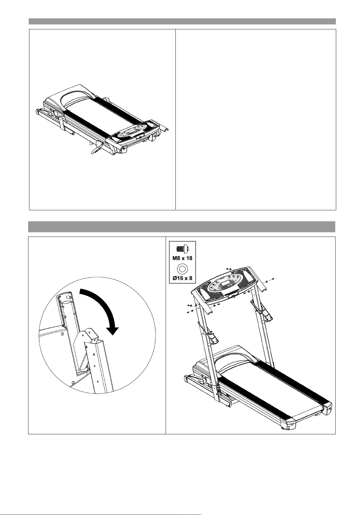
2. Rotate the console into position and secure using six
Ø16 x 8 Washers, six M8 x 18 Bolts.
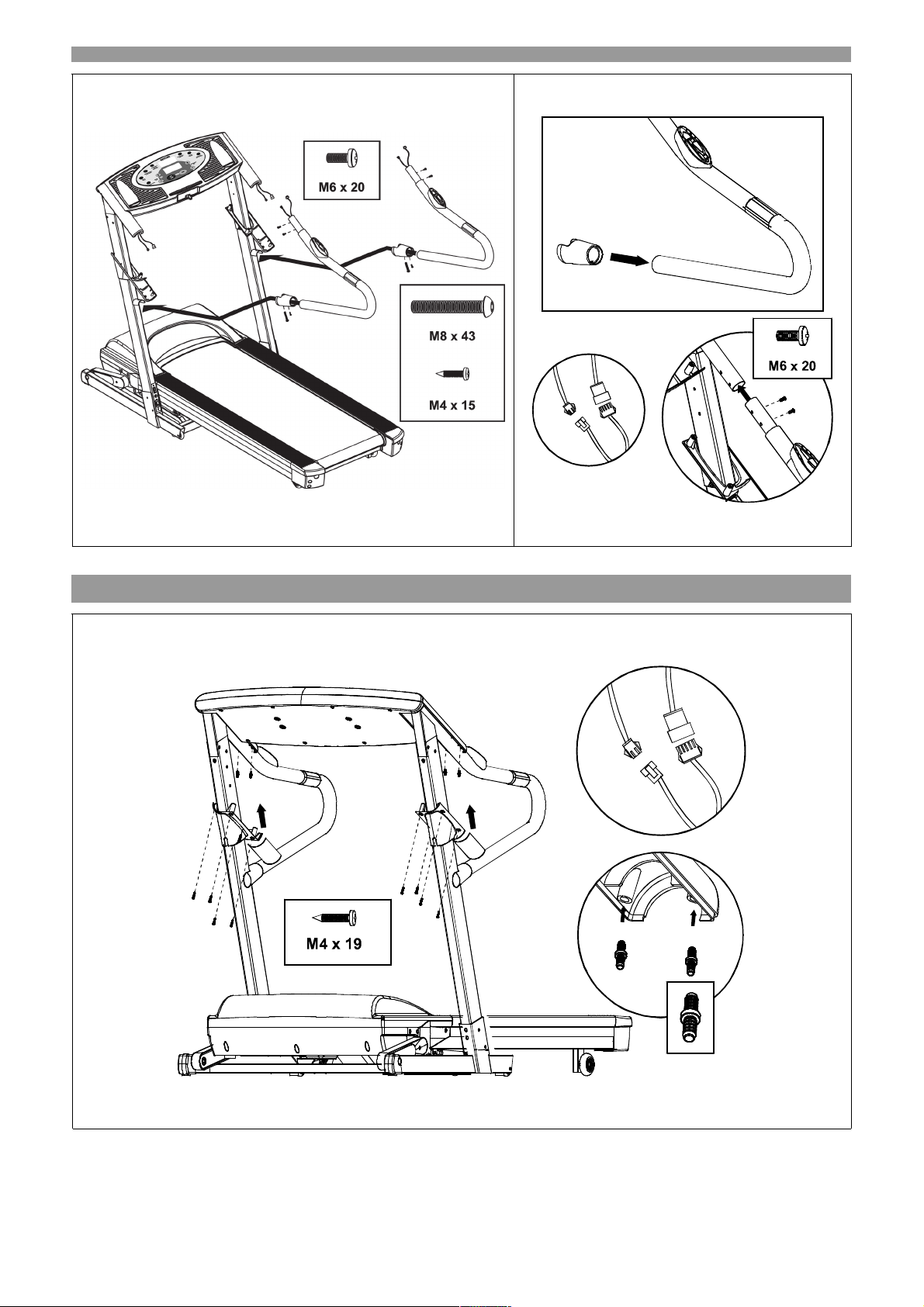
3. Connect the sensor wires between the Handlebars and
Console.
Insert the Handlebar Lower Covers onto the
Handlebars.
Attach the Handlebars to the Uprights and Console.
Secure using four M6 x 20 Screws, two M8 x 43 Bolts
and two M4 x 15 Screws.
4. Snap the four Fixing Inserts into the underside of the
Console. Slide up the Handlebar End Cap and
Handlebar End Join Cap and snap them into the Fixing
Inserts on the underside of the Console. Secure them
in place using eight M4 x 19 Screws.
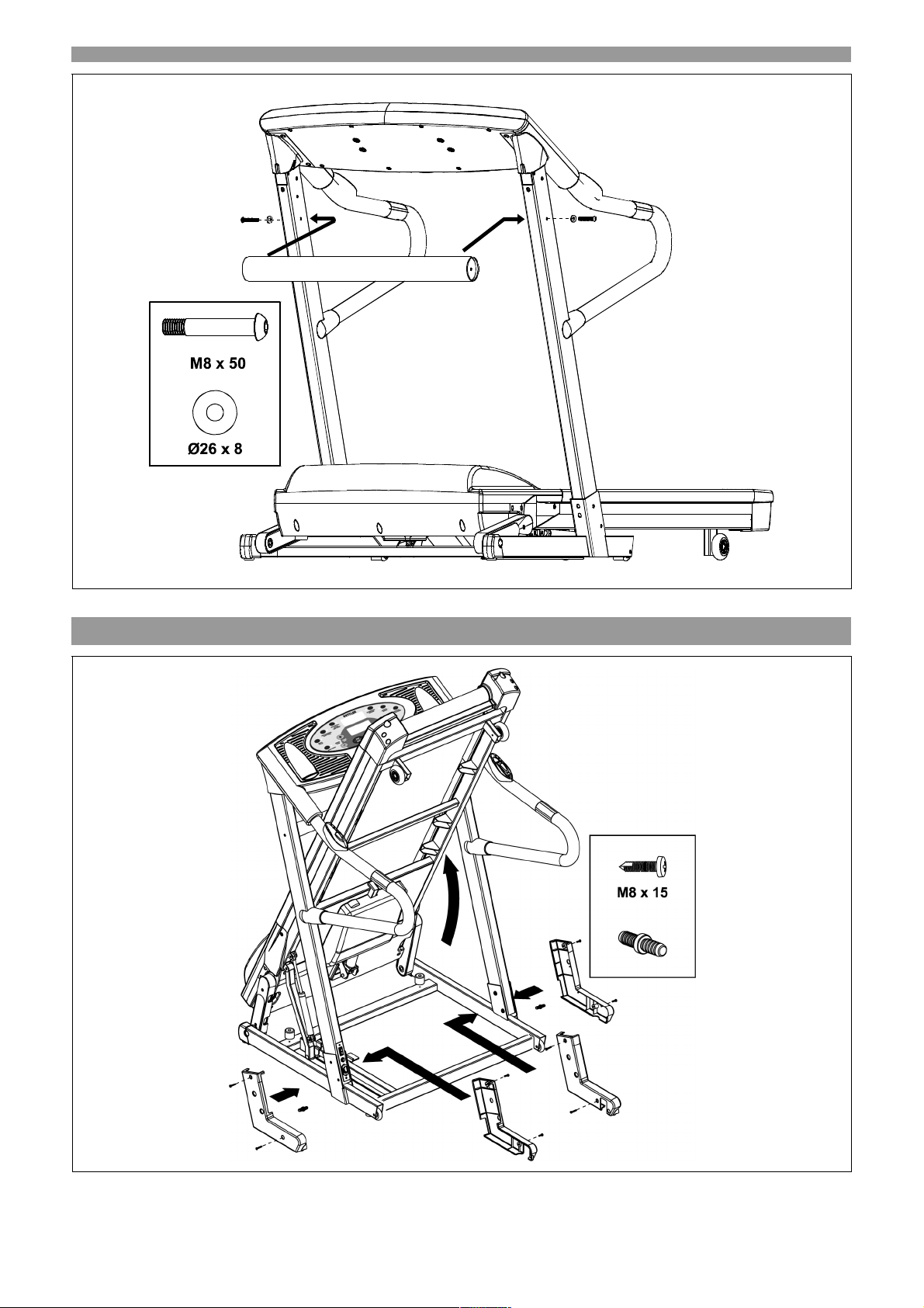
5. Attach the Cross Brace to the Uprights and secure
using two Ø26 x 8 Washers and two M8 x 50 Bolts.
6. Fold up the deck and make sure it locks in place.
Attach the Upright Plastic Shrouds to the Uprights and
secure using eight M8 x 15 Screws and two Fixing
Inserts.
1. Entnehmen Sie den Inhalt aus der Verpackung.
Bringen Sie die Ständer in Position und befestigen Sie
diese mit sechs Ø 16x8 Dichtungsringen, vier M8 x 12
Bolzen und zwei M8 x 50 Bolzen.
2. Bringen Sie die Konsole in Position und befestigen Sie
diese mit sechs Ø 16x8 Dichtungsringen und sechs
M8 x 18 Bolzen.
3. Befestigen Sie das Fühlerkabel zwischen den Griffen
und der Konsole. Bringen Sie die untere
Griffabdeckung an den Griffen an. Verbinden Sie die
Griffe mit den Ständern und der Konsole. Befestigen
Sie die Griffe mit vier M6 x 20 Schrauben, zwei M8 x
43 Bolzen und zwei M4 x 15 Schrauben.
4. Lassen Sie die vier Befestigungseinsätze an der
Unterseite der Konsole einrasten. Schieben Sie die
Abschlusskappen und die
Verbindungsabschlusskappen auf die Griffe und
lassen Sie diese in den Befestigungseinsätzen an der
Unterseite der Konsole einrasten und befestigen Sie
sie mit acht M4 x 19 Schrauben.
5. Bringen Sie die Querverstrebung an den Ständern an
und befestigen Sie die Verstrebung mit zwei Ø 26x8
Dichtungsringen und zwei M8 x 50 Bolzen.
6. Falten Sie die Laufbahn aus und stellen Sie sicher,
dass sie ordnungsgemäß einrastet. Bringen Sie die
Kunststoffblende an den Ständern an und befestigen
Sie die Blende mit acht M8 x 15 Schrauben und zwei
Befestigungseinsätze.
F
1. Sortez le contenu de la boîte d’emballage. Tournez les
montants pour les mettre en position et fixez-les en
utilisant six rondelles Ø 16x8, quatre boulons M8 x 12
et deux boulons M8 x 50.
2. Tournez la console pour la positionner correctement et
fixez-la à l’aide de six rondelles Ø 16x8, six boulons M8
x 18.
3. Branchez les fils du capteur entre le guidon et la
console. Placez les capuchons inférieurs sur le guidon.
Attachez le guidon aux montants et à la console. Fixezle tout en ayant recours à quatre vis M6 x 20, deux
boulons M8 x 43 et deux vis M4 x 15.
4. Encliquetez les quatre inserts de fixation dans le
dessous de la console. Montez le capuchon de bout et
le capuchon de jonction du guidon et encliquetez-les
dans les inserts de fixation situés sur le dessous de la
console. Fixez-les en position à l’aide de huit vis M4 x
19.
5. Attachez l’entretoise en croix aux montants et fixez-la à
l’aide de deux rondelles Ø 26x8 et de deux boulons M8
x 50.
6. Dépliez la plate-forme et assurez-vous qu’elle est
bloquée dans la bonne position. Attachez les
protecteurs aux montants et fixez-les au moyen de huit
vis M8 x 15 et deux inserts de fixation.
Méthode d’assemblage Loopband Montagestappen
NL
1. Haal de onderdelen uit de doos. Draai de staanders in
positie en borg ze met zes Ø 16x8 sluitringen, vier
M8x12 bouten en twee M8x50 bouten.
2. Draai de console in positie en borg deze met zes Ø
16x8 sluitringen, zes M8x18.
3. Verbind de sensorkabels tussen de handgrepen en de
console. Plaats de onderste handgreepbekledingen
over de handgrepen. Bevestig de handgrepen tussen
de staanders en de console en borg ze met vier
M6x20 schroeven, twee M8x43 bouten en twee M4x15
schroeven.
4. Klik de vier inzetstukken in de onderzijde van de
console. Schuif de eindkap en de verbindingskap van
de handgrepen op hun plaats en klik ze in de
inzetstukken. Borg ze met acht M4x19 schroeven.
5. Bevestig de dwarsbalk aan de staanders en borg deze
met twee Ø 26x8 sluitringen en twee M8x50 bouten.
6. Klap het loopvlak omhoog en controleer of deze goed
vergrendelt. Bevestig de plastic
staanderverstevigingen aan de staanders en borg
deze met acht M8x15 schroeven en twee inzetstukken.
1717
17
Page 7
Checklist
Messhilfe für Verschraubungsmaterial
Measuring help for screw connections Ayuda para la medición de los tornillos
Gabarit pour système de serrage Misure per i materiali di avvitamento
Meethulp voor schroefmateriaal Wzornik do po__czeñ œrubowych
1919
19
Page 8
1
2
20
2020
Page 9
3
4
2121
21
Page 10
5
6
22
2222
Page 11

5 Handhabung
Achtung! Stellen Sie das Laufband nur aufrecht, wenn die Steigung der Lauffläche in der niedrigsten Postition
ist! Ansonsten besteht Beschädigungsgefahr!
Warning! The treadmill must only be folded for storage with the inclination set in its lowest position, as this
could cause damage to the treadmill!
Attention! Soulevez uniquement le tapis lorsqu’il se trouve incline en position la plus basse ! Sinon il peut être
endommagé.
Let op! Zet de loopband alleen rechtop als de hellingshoek van het loopvlak in de laagste positie staat! Anders
bestaat er beschadigingsgevaar.
¡Atención! ¡Colocar la cinta rodante solamente en vertical cuando la inclinación de la zona de andar esté en la
posición más baja! De lo contrario existe riesgo de lesiones.
Attenzione! Il tappeto mobile può essere sistemato in posizione verticale soltanto se l’inclinazione del piano di
corsa è regolata sulla posizione più bassa! Altrimenti sussiste il rischio di danneggiamenti!
Uwaga! Bie_ni_ nale_y ustawia_ pionowo tylko pod warunkiem, _e powierzchnia bie_ni ustawiona jest w najni_szej
pozycji! Inaczej istnieje bezpiecze_stwo uszkodzenia.
Verriegeln:
Entriegeln:
To lock:
To unlock:
Verrouillage:
Déverrouillage:
Vergrendelen:
Ontgrendelen:
Enclavar:
Desenclavar:
Bloccaggio:
Sbloccaggio:
Zamykanie:
Odblokowywanie:
Klappen Sie die Lauffläche zum Transport hoch; Sie muss mit einem deutlich hörbaren
“Klick” einrasten.
Treten Sie den Hebel am rechten Innenrahmen mit dem Fuß herunter und halten Sie dabei
die Lauffläche fest. Nach dem Entriegelung können Sie dann die Lauffläche nach unten
klappen.
For transportation the running surface is to be folded at the top. It clicks into place with a
clear "Click".
Press the lever on the right inner part of the frame with the foot. Hold the running surface
firmly and fold downwards.
Pour le transport, replier la surface de marche vers le haut. Elle s’enclenche en émettant un
“Click” parfaitement audible.
Appuyer avec le pied sur le levier placé sur le cadre intérieur côté droit tout en maintenant la
surface de marche et l’abaisser.
voor transport het loopvlak omhoog klappen. Deze vergrendelt met een duidelijk hoorbare
“klik”.
de hendel aan het rechter binnenframe met de voet naar beneden drukken, daarbij het
loopvlak vast houden en naar beneden klappen.
para el transporte hay que rebatir hacia arriba la superficie de marcha. Encaja mediante un
“clic” audible.
presionar hacia abajo con el pie la palanca situada en el marco interior derecho, mantener
sujeta a la vez la superficie de marcha y abatir hacia abajo.
Per il trasporto è necessario ribaltare verso l’alto la piastra di scorrimento. Allo scatto in
posizione del piastra si ode un netto “click”.
Premere la leva verso il basso con un piede, afferrare contemporaneamente la piastra di
scorrimento e ribaltarla verso il basso.
do transportu nale_y podnie__ bie_ni_. Zatrzaskuje si_ ona z wyra_nym „klikni_ciem”.
Stop_ nacisn__ d_wigni_ na prawej ramie wewn_trznej, przytrzymuj_c przy tym bie_ni_ i otworzy_
j_ w dó_.
Page 12

6
7
8 Transport
24
2424
Page 13

Pflege und Wartung
ATTENTION: An insufficient lubrication and the
D
associated clear increase of friction leads to more wear
and tear and to damage of the treadmill belt, running
board, motor and circuit board!
Wartung des Bandes und der Laufplatte:
ACHTUNG: Die Schmierung, bzw. Pflege des Bandes ist die
wichtigste Wartungsmaßnahme! Schäden, die aufgrund
mangelnder oder unterlassener Pflege, bzw. Wartung des
Bandes entstehen, werden nicht durch die Garantie
abgedeckt!
Das Laufband ist werksseitig vorgeschmiert, normalerweise
sollte innerhalb des ersten Jahres oder innerhalb von 500
Betriebsstunden keine weitere Schmierung notwendig sein.
Danach sollte etwa alle drei Monate eine Schmierung des
kalten Bandes mit Silikonöl vorgenommen werden. Prüfen
Sie, ob sich zwischen Laufband und Bodenplatte Reste von
Silikonöl befinden. Ist dies der Fall, ist noch keine weitere
Schmierung notwendig. Andernfalls heben Sie das Band
leicht an, so dass Sie seitlich ausreichend Silikonöl von vorne
nach hinten auf der Bodenplatte aufbringen können.
Beginnen Sie dabei etwa 15 cm vom Bandeinlauf
Wiederholen Sie dies auch von der anderen Seite, sprühen
Sie pro Seite etwa 4 Sekunden. Lassen Sie dann das Band
mit einer geringen Geschwindigkeit etwa 2 Minuten laufen,
damit sich das Silikonöl einarbeiten kann.
Überschüssiges Gleitmittel abwischen.
ACHTUNG: Eine nicht ausreichende Schmierung und eine
damit verbundene deutliche Zunahme der Reibung führt zu
einem starken Verschleiß und einer Beschädigung von
Endlosband, Laufplatte, Motor und Platine!
Maintenance of the belt and the running board:
ATTENTION: The lubrication and care of the belt is the most
important maintenance measure! Damages which occur from
defective or neglected care and maintenance of the belt are not
covered by the guarantee!
The walking belt has been pre-lubricated at the factory.
However, it is recommended that the walking board be
checked periodically for lubrication to ensure optimal treadmill
performance. Your treadmill should not have to be lubricated
usually within the first year or 500 hours of use. Every 3
months of operation lift the sides of the walking belt and feel
the top surface of the walking board as far as you can reach. If
you feel signs of silicone, no further lubrication is required. If it
feels dry to the touch, follow the instructions below:
While lifting the side of the walking belt, position the spray
nozzle between the walking belt and the board approximately
6" from the front of the treadmill. Apply the silicone spray to the
walking board, moving from the front of the treadmill to the
rear. Repeat this on the other side of the belt. Spray
approximately 4 seconds on each side. Let the belt run with
low speed for approximately 2 minutes so that the silicon can
“set in”. Wipe away any superfluous lubricant.
Entretien du tapis et de la plaque de marche:
ATTENTION: Le graissage ou les soins du tapis sont
les mesures d’entretien les plus importantes ! Les
deteriorations issues d’un manque de soins ou
d’entretien du tapis ne sont pas couvertes par la
garantie !
Le tapis de course est graissé en usine. En principe, il
ne faut aucun graissage consécutif durant les
premières années ou en l’espace des 500 premières
heures de fonctionnement.
Par la suite, un graissage du tapis refroidi s’impose
environ tous les trois mois à l’huile de silicone.
Vérifiez s’il y a des restes d’huile de silicone entre le
tapis et la plaque de fond. Dans ce cas, il n’est pas
encore nécessaire de graisser le tapis. En cas
contraire, soulevez légèrement le tapis, afin de pouvoir
appliquer suffisamment d’huile de silicone de l’avant
vers l’arrière sur la plaque de fond.
Commencez à environ 15 cm de l’entrée du tapis.
Répétez l’opération de l’autre côté, vaporisez la
graisse durant environ 4 secondes de chaque côté.
Faites ensuite marcher le tapis à vitesse réduite
environ 2 minutes pour faire pénétrer l’huile.
Essuyez l’huile superflue.
ATTENTION: Un graissage insuffisant et la friction
exagérée qui en découle peuvent user très vite et
détériorer le tapis, la plaque de marche, le moteur et la
platine!
Onderhoud van de band en het loopvlak:
LET OP: het smeren cq. onderhoud van de band is de
belangrijkste onderhoudsmaatregel. Schades die
wegens slechte of achterwege gelaten onderhoud van
de band ontstaan, vallen niet onder de garantie!
De loopband is in de fabriek reeds gesmeerd, normaal
gezien is in het eerste jaar of binnen 500 gebruiksuren
géén extra smering van de band noodzakelijk.
Daarna dient elke drie maanden een smering van de
koude band met siliconenspray plaats te vinden.
Controleer of zich tussen de loopband en de
bodemplaat resten siliconenolie bevinden. Is dit het
geval, is het nog niet nodig om de band te smeren.
Is dit niet het geval, de band iets optillen zodat u vanaf
de
zijkant voldoende siliconenspray van voor naar achter
op de bodemplaat kunt aanbrengen. Begin daarbij ca.
15 cm van de bandinloop. Herhaal dit ook aan de
andere zijde. Sproei per kant ca. 4 seconden. Laat dan
de band met een lage snelheid circa 2 minuten lopen,
zodat de siliconenolie zich kan verspreiden.
Overtollige olie verwijderen.
LET OP: het niet voldoende smeren en een daarmee
verbonden duidelijke toename van de wrijving voert tot
sterke slijtage en beschadiging van de loopband, het
loopvlak, de motor en de printplaat!
25
2525
Page 14

ATENCIÓN
4 sekundy z ka_dej strony. Nast_pnie uruchomi_ ta_m_ z
medida más importante de mantenimiento. Los daños
causados por un cuidado o mantenimiento deficiente o
negligente de la cinta, no están cubiertos por la garantía.
La cinta de rodadura viene prelubricada de fábrica,
normalmente no es necesaria la lubricación dentro del
primer año o de las primeras 500 horas de servicio.
Posteriormente, debe realizarse aproximadamente cada tres
meses un lubricado de la cinta en frío con aceite de silicona.
Compruebe si entre la cinta y la plataforma base existen
restos de aceite de silicona. Si es así, no es necesaria una
nueva lubricación. En caso contrario, levante ligeramente
la cinta, de forma que pueda aplicar suficiente aceite de
silicona desde adelante hacia atrás sobre la plataforma.
Empiece a aprox. a 15 cm. de la entrada de la cinta.
Vuelva a hacerlo también desde el lado contrario, pulverice
en cada lado unos 4 segundos. Después deje correr la cinta
a baja velocidad aproximadamente 2 minutos, para que el
aceite de silicona pueda introducirse bien.
Lave el engrasante que sobre.
ATENCIÓN: una lubricación insuficiente y el significativo
aumento del rozamiento asociado a ésta, conlleva un fuerte
desgaste y daños en el bucle continuo, la plataforma de
rodadura, el motor y la pletina.
Manutenzione del nastro e della piastra di
scorrimento:
ATTENZIONE: Le operazioni di lubrificazione e cura del nastro
fanno parte delle più importanti misure di manutenzione! I
danni derivanti da una cura, ovvero da una manutenzione
inappropriata o addirittura tralasciata, non sono coperti
dalla garanzia!
Il nastro di scorrimento viene lubrificato in fabbrica.
Generalmente dopo le prime 500 ore di servizio oppure entro il
primo anno non è necessario lubrificarlo.
Dopo tale periodo sarebbe comunque opportuno lubrificare
il nastro freddo impiegando olio a base di silicone. Verificare se
tra il nastro e la piastra di fondo si trovano dei residui di olio di
silicone. Se così fosse, sarebbe premature eseguire
un’ulteriore lubrificazione. In caso contrario bisognerà sollevare
leggermente il nastro per consentire di versare lateralmente
dalla posizione anteriore in quella posteriore una sufficiente
quantità di olio di silicone sulla piastra di fondo. Iniziare ad una
distanza di circa 15 cm dall’entrata del nastro. Ripetere
quest’operazione anche sull’altro lato. Spruzzare ogni lato per
circa 4 secondi. Lasciar quindi scorrere per circa 2 minuti e a
velocità moderata il nastro onde consentire all’olio di silicone di
distribuirsi.
Rimuovere il lubrificante superfluo.
ATTENZIONE: un'insufficiente lubrificazione comporta un
evidente aumento dell’attrito che provoca una forte usura e
danneggia di conseguenza sia il nastro continuo che la piastra
di fondo, ma anche il motore e la platina!
: el lubricado y cuidado de la cinta es la
ma__ pr_dko_ci_ na ok. 2 minuty, aby olej silikonowy móg_
zosta_ rozprowadzony.
Usun__ nadmiar smaru _lizgowego.
UWAGA: Niewystarczaj_ce smarowanie i zwi_zany z
tym znaczny wzrost tarcia powoduje silne zu_ycie i
uszkodzenie ta_my, p_yty bie_ni, silnika i p_ytki!
Konserwacja ta_my i p_yty bie_ni:
UWAGA: Smarowanie wzgl. piel_gnacja ta_my to najwa_niejsza
operacja konserwacyjna! Uszkodzenia
spowodowane niewystarczaj_c_ lub zaniedban_ piel_gnacj_ wzgl.
konserwacj_ nie s_ obj_te gwarancj_! Ta_ma bie_ni jest
nasmarowana fabrycznie. Normalnie przez pierwszy rok lub 500
roboczogodzin dodatkowe smarowanie nie powinno by_ potrzebne.
Nast_pnie nale_y raz na trzy miesi_ce nasmarowa_ zimn_ ta_m_
olejem silikonowym. Sprawdzi_, czy pomi_dzy ta_m_ bie_ni i p_yt_
podstawy s_ jeszcze pozosta_o_ci oleju silikonowego. Je_eli s_, to
smarowanie nie jest jeszcze konieczne. W przeciwnym razie nale_y
lekko podnie__ ta_m_, aby mo_na by_o z boku, od przodu do ty_u,
wprowadzi_ wystarczaj_c_ ilo__ oleju silikonowego na p_yt_
podstawy. Zacz__ przy tym na ok. 15 cm od wlotu ta_my. Powtórzy_
t_ sam_ operacj_ równie_ od drugiej strony, natryskuj_c przez ok.
26
2626
Page 15

D
Leistungstabelle
GB F
Performance table Tableau de performances Prestatietabel
E
Tabla de rendimiento
Datum Ruhepuls P1
D
GB
Date Restpulse Stress pulse Recovery pulse Speed Time (min) Distance (km)
F
Date
NL
Datum Rustpols Belastings-pols
E
Fecha
I
Data Polso riposo
PL
Data
Pouls au
repos
Pulso en
reposo
t_tno
spoczynkowe
BelastungspulsP2Erholungspuls
Pouls en charge
Pulso
bajo esfuerzo
Polso
affaticamento
t_tno przy
obci__eniu
I
Tabella delle prestazioni Tabela wyników
Belastungs-
stufe
Pouls de
récupération
Ontspannings-
pols
Pulso
de recuperación
Polso ripresa Fase dicarico
t_tno w
fazie odpoczynku
Angle
d´inclination
Hellingshoek
Escalón de
carga
stopie_
obci__enia
Zeit
(min.)
Temps
(min.)
Tijd (min.)
(min.)
Tiempo
(min.)
Tempo
(min.)
Czas
(min.)
NL
PL
Entfernung
(km)
Distance (km)
Afstand
(km)
Distancia
(km)
Percorso
(km)
odleg_o__
(km)
Energie-
verbrauch
Energy
consumption
Dépense
d´énergie
Calorieen-
verbruik
Consumo
de energía
Consumo
energetico
Zu_ycie
energii
Fitnessnote
Fitness Mark
Note
Waard. cijfer
Nota
Voto
Ocena
sprawno_ci
2727
27
Page 16

Ersatzteilzeichnung
0
00
Page 17

Ersatzteilzeichnung
11
1
Page 18

Ersatzteilliste Laufband „TRAVELLER“ Art.-Nr. : 7885-000
Part Name
1 Computer 68001000
2 Console Top 68001001
3 Console Bottom 68001002
65 M4 x 15mm Screw 68001003
4 Safety Key 68001004
13 Motion Control Sensor 68001005
14 Hand Pulse Sensor 68001006
Kettler No.
22 Foot Up Lock
25 Power Switch
39 Ø16 X 8 Washer
42 M8 Nut
66 Elevation Motor
78 M10 x 67mm Bolt
49 Side Rail (R+L)
50 Deck Rear End Cap (R+L)
51 Front Roller Shaft
52 Front Roller
53
54
58 Driving DC Motor 68001019
60 Motor Control Board 68001020
83 Transfer Board 68001021
84 Chock 68001022
86 Filter 68001023
Rear
Roller Shaft
Rear
Roller
68001007
68001008
68001009
68001010
68001011
68001012
68001013
68001014
68001015
68001016
68001017
68001018
89 Transformer 68001024
93 Power Cord 68001025
A Hardware 68001026
B Manual 68001027
C Silicon Spray 680010
2
22
Page 19

Blockschaltbild 7885-000
33
3
Page 20

HEINZ KETTLER GmbH & Co. KG • Postfach 1020 • D- 59463 Ense-Parsit
KETTLER Austria GmbH • Gewerbestraße 2 • A-5322 Hof/Sbg.
Trisport AG • Im Bösch • CH-6331 Hünenberg
KETTLER Ltd. • KETTLER House, Merse Road • North Moons Moat • Redditch, Worcestershire • B 98 9
HL • Great Britain
KETTLER International Inc. • P. O. Box 2747 • Virginia Beach • VA 23450 • USA
KETTLER S. a. r. l. • B. P. 2 •l F-67130 Lutzelhouse
Trisport AG •l Im Bösch • CH-6331 Hünenberg
KETTLER Benelux B. V. • Filiaal Belgie • Brandekensweg 9 • B-2627 Schelle
KETTLER Benelux B.V. • Indumastraat 18 • NL–5753 RJ Deurne
KETTLER Benelux B.V. • filiaal België • Brandekensweg 9 • B–2627 Schelle
BM Sportech S.A. Crata. • De Logrono Km 6 • Z.l El Portazgo nave 94 • 50011 Zaragoza
KETTLER SRL • Strada Per Pontecurone 5 • I–15053 Castelnuovo Scriva (AL)
KETTLER Polska • ul. Kossaka 110 • PL–64-92 Pila
http://www.kettler.de
4
44
Page 21

COMPUTER INSTRUCTIONS
C O MP U T E R IN S T R U C T I O N S
MODEL NUMBER: LCD 6K for KETTLER HKS TRAVEL LER
Page 22

2
A
C
E
G
LCD 6K COMPUTER INSTRUCTIONS
COMPUTER OPERATION
B C DEF GH
A
Safety Key
START Button
LCD 2 Window
SPEED UP/DOWN Buttons
BUTTON FUNCTIONS
START – Press to start exercise at init ial spee d 0.5MPH / 0.8KPH .
STOP / ENTER
a. Press to confirm program and preset function values setting mode.
b. Press to run setting procedure before pressing the START KEY.
c. Press to stop exercise during workout time.
SPEED UP (+)
a. Press to increase exercise speed by 0.1MPH/KPH.
b. Hold the button to rapidly increase speed by 0.5MPH/KMPH per second and release the button to stop the function.
SPEED DOWN (-)
a. Press to decrease exercise speed by 0.1MPH/KPH.
b. Hold the button to rapidly decrease speed by 0.5MPH/KMPH per second and release the button to stop the function.
MOTION CONTROL
a. To activate the Motion Control press the button until the LED light turns on.
b. To deactivate the Motion Control press the button until the LED light turns off.
INCLINE UP (+) / DOWN (-)
a. Press up or down to change incline level.
b. Press to select programs and preset related function value.
B INCLINE UP/DOWN Buttons
D LCD 1 Window
F STOP/ENTER Button
H MOTION CONTROL Button
Page 23

3
LCD 6K COMPUTER INSTRUCTIONS
COMPUTER OPERATION
MOTION CONTROL OPERATION : (Photos may differ slightly from your treadmill)
1. Press the MOTION CONTROL button on the console to switch the
motion control function on and off:
• When the LED light is ON the MOTION CONTROL is active.
• When the LED light is OFF the MOTION CONTROL is off.
2. After switching on the MOTION CONTROL wave your right hand
approximately 6 inches above the motion sensor on the right
handle bar to increase the speed. The sens or will sound one short
BEEP per scan and speed up by 0.1 MPH per BEEP. Holding
your right hand approximately 6 inches above the right sensor
constantly results in the sensor sounding one long BEEP per
second and speeding up by 0.5 MPH per BEEP.
3. Wave you left hand approximately 6 inches above the motion
sensor on the left handle bar to decrease the speed. The sensor
will sound one short BEEP per scan and decrease speed by 0.1
MPH. Holding your left hand approximately 6 inches above the left
sensor constantly results in the sensor sounding one long BEEP
per second and decreasing speed by 0.5 MPH per BEEP.
1. Press button to turn on.
2. Use right sensor to s peed up.
3. Use l eft sen sor to sl ow d own .
4. Wave both hands approximately 6 inches above both motion
sensors at the same time. The sensor will sound two short BEEP
sounds then stop the belt.
• Always switch off the motion control function by pressing the
MOTION CONTROL button on the console before turning off
the power to the treadmill.
4. U s e b oth sens ors to stop belt.
Page 24

4
LCD 6K COMPUTER INSTRUCTIONS
COMPUTER OPERATION
SAFETY KEY
The safety key must be inserted into the slot on the console in order to operate the treadmill. Always insert the safety key
and attach the clip to your clothing at your waist before beginning your workout. If you should encounter problems and need
to stop the motor quickly, simply pull on the cord to disengage the safety key from the console. To continue operation first
turn the power switch to off and set the speed controller to stop. Next turn the power swit ch to on a nd re inse rt t he sa fet y key
into the console.
POWER ON
Set the POWER SWITCH, located on the base frame, to ON and insert the SAFETY KEY. The UPPER LCD and LOWER
LCD sc re ens light up all digits and enter the POWER ON mode. The UPPER LCD SPEED/DISTANCE window shows “0.0”
and 6 program LED lights blink individually. The LOWER LCD shows 0 on all windows.
SLEEP MODE
When the power is ON the computer will automatically enter SLEEP MODE if it is left idle for 3 minu tes without r eceiving any
input. Press any button to return to POWER ON status when the computer is in the SLEEP MODE.
DISPLAY MODE
This feature is designed only for store display purpose. To cancel the SLEEP MODE feature, pull out the safety key, press
and hold the SPEED UP and DOWN buttons, insert the safety key to power on the treadmill. After one short beep sound, the
SLEEP MODE will be cancelled and the LCD will not go off as long as the power switch stays on and the safety key is
inserted properly.
BEEPER ON/OFF
This feature allows the user to switch the computer beeper on and off. Press and hold the START and INCLINE DOWN (-)
buttons, the TIME display on LCD2 shows “ON” as the factory setting. Press the INCLINE UP (+) or DOWN ( -) buttons to
switch between “ON ” and “OFF ” (shown on the TIME display) to switch the beeper on or off . Press the STOP button to return
to the POWER ON mode.
ENGLISH / METRIC CONVERSION
The computer has been preset to calculate and show all information in English (miles, pounds, inches). The computer can be
set to display information in Metric (kilometers, kilograms, centimeters). To do this set the POWER SWITCH, located on the
base frame, to ON. Press and hold the START butto n. In sert the SAFETY KEY. The computer will sound one short BEEP
and the UPPER LCD will show KM and blink. Press the INCLINE UP/DOWN button to switch between KM and ML. KM
means Metric and ML means English. Press the STOP/ENTER button to confirm the setting and return to POWER ON
status after one long beep sound.
Metric display
English display
Page 25

5
LCD 6K COMPUTER INSTRUCTIONS
COMPUTER OPERATION
QUICK START
When the treadmill is in POWER ON status, press the START button to activate the QUICK START. The SPEED LCD
counts down 3 seconds with 3 short beeps t he n s ta rt s from 0.5 MPH/0.8 KPH. Press the SPEED UP/DOWN buttons to
adjust the speed. Press the INCLINE UP/DOWN buttons to elevate the treadmill. The TIME, CALORIES and DISTANCE
count up from 0. The PULSE LCD shows P until you hold the hand pulse grip sensors or wear the chest belt heart rate
transmitter (optional) then the PULSE LCD will display the current pulse during the workout.
STOP/PAUSE
During the workout, press the STOP/ENTER button to PAUSE the treadmill, all workout data will be frozen. Press the
START button to resume the workout and all data will continue counting. If the STOP/ENTER button is pressed twice , the
treadmill will return to POWER ON status and all workout information will return to 0.
RECOVERY
A. For the QUICK START and P1 MANUAL program, follow the step below to start the RECOVERY function:
During the QUICK START and P1 MANUAL program, press the STOP button to finish the workout and hold onto the
hand pulse contact grip (no need to hold the hand pulse contact if using the chest belt transmi tter) within 10
seconds. The pulse sensor will pick up the user pulse then start the RECOVERY function.
B. For the P2 - P6 programs , follow the step below to start the RECOVERY function:
After completing the workout for program P2 - P6, the computer will start a one minute COOL DOWN function. In
the first 10 seconds the TIME display will show “COOL ” and blink for 10 seconds. P re ss the STOP button and hold
onto the hand pulse con tac t gr ip ( no n eed to hold the hand puls e co nta ct i f us ing the chest belt transmitter) while the
display shows “COOL”. The pulse sensor will pick up the user’s pulse then start the RECOVERY function.
During the RECOVERY function , the TIME display will count down 60 seconds from “01:00” to “00:00” and the LCD 2 window
displays “R” on the dot ma trix a rea. Pulse display will show the current user’s p ul s e . If the pulse sensor cannot pick up the
user’s pulse, the pulse display will show “P” and blinking. To stop the RECOVERY function, press the STOP button during
the RECOVERY function to return to the STOP/PAUSE mode.
Calculation of the fitness note:
Note = 6 – ((10 x (P1–P2)) / P1)2
P1= Stress pulse, P2 = Recovery pulse
F1 = Very good
F6 = Insufficient
COMPUTER PROGRAM OPERATION
To select the program, press the program buttons when the treadmill is in POWER ON status. For the first time user, you
have to set up the user information and assign your USER ID from U 1 to U 9 before the program starts .
SET UP USER INFORMATION
Press any program button on the computer panel. For the first time use of the treadmill, the upper LCD will show a blinking
U1 and the lower LCD will show factory default setting values of user weight, height, age and target heart rate. Press the
INCLINE UP/DOWN buttons to choose the USER ID from U1 to U9 and press the STOP/ENTER button to assign your
user ID.
Page 26

6
LCD 6K COMPUTER INSTRUCTIONS
COMPUTER OPERATION
SET USER GENDER
After assigning your user ID, the gender icon will display on the lower LCD. Press the INCLINE UP/DOWN buttons to switch
between male and female icon then press the STOP/ENTER button to select your gender.
SET USER WEIGHT
After setting the user gender, the lower LCD will display W. The TIME LCD display now shows the blinking factory setting
user weight 150LB/68KG. Press the INCLINE UP/DOWN buttons to adjust the user weight correctly and press
STOP/ENTER to set the user weight.
SET USER HEIGHT
After setting the user weight, the lower LCD will display H. The CALORIES LCD display now shows the blinking factory
setting user height 5’3”/160CM. Press the INCLINE UP/DOWN buttons to adjust the user height correctly and press
STOP/ENTER to set the user height.
SET USER AGE
After setting the user weight, the lower LCD will display A. The INCLINE LEVEL LCD display now shows the blinking factory
setting us er age 35. Press the INCLINE UP/DOWN buttons to adjust the user age correctly and press STOP/ENTER to set
the user age.
SET USER TARGET HEART RATE
When you set up the user AGE, please note the user TARGET HEART RATE will be adjusted with the user AGE according
to the factory setting. The factory TARGET HEART RATE setting is based on 85% of the maximum heart rate. The
maximum heart rate is calculated as 220 minus the user age. For age 35, the maximum user heart rate should be 185 and
85% of user heart rate , which is 157. After setting the user age, the lower LCD will show P and the PULSE LCD shows the
blinking factory target heart rate setting. Press the INCLINE UP/DOWN buttons to adjust the user target heart rate properly
for your own physical condition and press the STOP/ENTER button to set the user TARGET HEART RATE.
Page 27

7
LCD 6K COMPUTER INSTRUCTIONS
COMPUTER OPERATION
Now, you have completed the user information set up. For the 2nd or other m ember in the family, ple ase assign a different
user ID. This treadmill can allow set and memorize 9 different user’s information. For the repeat user, after pressing the
program button, please press the INCLINE UP/DOWN buttons to select the USER ID that you assigned previously. Each
time when the treadmill is switched off and switched on again it will enter the select program procedure. The user ID will
show the user ID of the previous user.
OPERATE PROGRAM
After completing the USER INFORMATION SET UP, prior to starting the program you selected, please follow the procedure
to operate the different programs as described below:
P1 MANUAL PROGRAM
If you select the P1 MANUAL program, the upper and lower LCD will show the following:
After completing the user information set up, the SPEED LCD displays the initial speed 2.0MPH/3.2KPH and the PULSE LCD
displays P. TIME, CALORIES AND INCLINE LEVEL all show 0. Press the START button to start the workout. Press the
SPEED UP/DOWN buttons to adjust the speed from 0.5MPH to 10MPH and press the INCLINE UP/DOWN buttons to adjust
the incline level from level 0 to 15. Distance, time, calories all count up from 0.
P2 INTERVAL INCLINE
If you select the P2 INTERVAL INCLINE program, the upper and lower LCD will show the following:
After completing the user information set up, SPEED, CALOR IES and PULSE LCD display 0. The TIME display shows
factory setting 24:00 and the blinking workout load level shows 1. Press the INCLINE UP/DOWN buttons to adjust the
workout load level from 1 to 12 then press the STOP/ENTER button to confirm the setting.
Then the blinking TIME LCD displays 24:00. Press the INCLINE UP/DOWN buttons to adjust the total workout time and press
the STOP/ENTER button to confirm the setting.
Press the START button to start the workout. SPEED starts fro m 2.0 MPH /3.2 KPH. Th e TIME counts down from the set up
workout time. The CALORIES and DISTANCE count up from 0. INCLINE LEVEL follows t he pr e -set chart as follows:
Page 28

8
LCD 6K COMPUTER INSTRUCTIONS
COMPUTER OPERATION
LEVEL MIN. LEVEL MAX. LEVEL
1 0 4
2 1 5
3 2 6
4 3 7
5 4 8
6 5 9
7 6 10
8 7 11
9 8 12
10 9 13
11 10 14
12 11 15
During the workout, press the SPEED UP/DOWN buttons to adjust the speed. Users c an overwrite t he inc line level by
pressing the INCLINE UP/DOWN buttons.
COOL DOWN
After the pre-set TIME counts down to 0, treadmill will start a one minute cool down program. The TIME LCD will display
COOL and blink for 10 seconds and continue counting down 50 seconds at speed 2 MPH/3.2KPH. After a one minute cool
down, the treadmill will stop and return to P2 start display. Press STOP/ENTER to go to POWER ON status.
P3 INTERVAL SPEED
If you select the P3 INTERVAL SPEED program, the upper and lower LCD will show the following:
After completing the user information set up, the SPEED, CALORIES and PULSE LCD display 0. The TIME display shows
factory setting 24:00 and a blinking workout load level shows 1. Press the INCLINE UP/DOWN buttons to adjust the workout
load level from 1 to 12 then press the STOP/ENTER button to confirm the setting. Then the TIME LCD will display a blinking
24:00. Press the INCLINE UP/DOWN buttons to adjust the total workout time and press STOP/ENTER button to confirm the
setting.
Press the START button to start the workout. The SPEED start and change follows the pre-set workout load speed chart as
below. The TIME counts down from the set up workout time. The CALORIES and DISTANCE count up from 0. INCL INE
LEVEL starts from level 0.
LEVEL MIN. SPEED MAX. SPEED
1 1.8 3.0
2 2.0 3.4
3 2.2 3.8
4 2.4 4.2
5 2.6 4.6
6 2.8 5.0
7 3.0 5.4
8 3.2 5.8
9 3.4 6.2
10 3.6 6.6
11 3.8 7.0
12 4.0 7.2
Page 29

9
LCD 6K COMPUTER INSTRUCTIONS
COMPUTER OPERATION
During the workout, press the INCLINE UP/DOWN button to adjust the incline level. Users ca n ov erw rit e th e sp eed by
pressing the SPEED UP/DOWN buttons.
COOL DOWN
After the pre-set TIME counts down to 0, the treadmill will start a one minute cool down program. The TIME LCD will display
COOL and blink for 10 seconds and continue counting down 50 seconds at a speed of 2MP H/3 .2K PH. After the one minute
cool down, the treadmill will stop and return to P2 start display. Press STOP/ENTER to go to PO W ER ON s t atus .
P4 WEIGHT LOSS
If you select the P4 WEIGHT LOSS program, the upper and lower LCD will show the following:
After completing the user information set up, the SPEED, CALORIES and PULSE LCD display 0. The TIME display shows
factory setting 24:00 and the blinking workout load level shows 1. Pr e s s the INCLINE UP/DOWN buttons to adjust the
workout load level from 1 to 12 then press the STOP/ENTER button to confirm the setting. Then the TIME LCD displays a
blinking 24:00. Press the INCLINE UP/DOWN buttons to adjust the total workout time and press the STOP/ENTER button to
confirm the setting.
Press the START button to start the workout. The SPEED and INCLINE follow the pre-set workout load chart. The TIME
counts down from the set up workout time. Distance and Calories count up from 0.
LEVEL MIN. SPEED MAX. SPEED
1 1.6 2.8 0 3
2 1.8 3.0 0 4
3 2.0 3.2 1 5
4 2.2 3.4 1 6
5 2.4 3.6 2 7
6 2.6 3.8 2 8
7 2.8 4.0 3 9
8 3.0 4.2 3 10
9 3.2 4.4 3 11
10 3.4 4.6 4 12
11 3.6 4.8 4 13
12 3.8 5.0 4 14
MINI. INCLINE
LEVEL
MAX INCLINE
LEVEL
During the workout, users can overwrite the speed by pressing the SPEED UP/DOWN buttons and overwrite the incline level
by pressing the INCLINE UP/DOWN buttons.
COOL DOWN
After the pre-set TIME counts down to 0, the treadmill will start a one minute cool down program. The TIME LCD will display
COOL and blink for 10 seconds and continue counting down 50 seconds at a speed of 2MP H/3 .2K PH. After a one minute
cool down, the treadmill will stop and return to P2 start display. Press STOP/ENTER to go to POWER ON status.
Page 30

10
LCD 6K COMPUTER INSTRUCTIONS
COMPUTER OPERATION
P5 5K SELF LEARING / COMPETITION
If you select the P5 5K SELF LEARNING / COMPETITION program, the upper and lower LCD will show the following:
After completing the user information set up, the DISTANCE LCD shows preset distance 3M/5KM. The TIME, CALORIES
and INCLINE LEVEL LCD display 0 and the PULSE LCD display shows P.
Press the START button to start the program. Speed starts from 2.0MPH/3.2KP H. The TIME and CALORIES count up from
0. Incline level follows the factory pre -set profile. DISTANCE counts down from 3ML/5KM. During the workout you can
adjust the speed by pressing the SPEED UP/DOWN buttons and overwrite the INCLINE LEVEL by pressing the INCLINE
UP/DOWN buttons.
COOL DOWN
After the pre-set DISTANCE counts down to 0, the treadmill will start a one minute cool down program. The TIME LCD will
display COOL and blink for 10 seconds and continue counting down 50 seconds at a speed of 2MPH/3.2KPH. After a one
minute cool down, the trea dmi ll will st op and return to P2 star t di splay. Press STOP/ENTER to go to POWER ON status.
P6 HEART RATE CONTROL
If you select the P6 5K HEART RATE CONTROL program the upper and lower LCD windows will display the following:
After completing the user information set up the TIME display shows the blinking factory pre -set workout time 60:00. Press
the INCLINE UP/DOWN buttons to adjust the workout time and press the STOP/ENTER button to confirm. The upper LCD
window displays initial speed of 2.0MPH/3.2KPH and the lower LCD window shows initial warm up time of 3:00.
Press the START button to start the 3 minute WARM UP program. Speed starts from 2.0MPH/3.2KPH and INCLINE LEVEL
starts from level 0. Please keep your hand on the hand pulse grips all the time during this workout in order to monitor your
pulse correctly. During the program, if the heart rate monitor fails to sense the pulse you will see “P” blinking on the PULSE
display. If the heart rate monitor senses the pulse properly you will see the stable heart beat sign and the correct pulse
readout on the PULSE display. The computer will sense the user’s pulse every 30 seconds. During the warm up program
you can press the STOP/ENTER button to pause or stop the program or press the START button to re-start the program.
Other buttons will not react during this warm up process.
Page 31

11
Strap chest belt across the front below the chest line.
LCD 6K COMPUTER INSTRUCTIONS
COMPUTER OPERATION
During the warm up program if the heart rate monitor fails to sense the user’s pulse (the PULSE display will sh ow “P” and
blink), the computer will not change the speed. If the heart rate monitor senses the user’s pulse properly and the actual
user’s pulse does not reach 65% of the maximum heart rate ((220-age) x 65%), then the speed will increase by
0.5MPH/0.8KPH per 30 seconds. If the actual pulse reaches 65% of the maximum heart rate, the speed will remain
unchanged. If the actual pulse reaches 65% of the maximum heart rate for over one minute, then the speed will be
maintained the same until the warm up program finishes .
If the actual user’s pulse fails to reach 65% of the maximum heart rate within the first 3 minutes of warm up, the computer will
continue the second 3 minute warm up program. All workout information continues to count up and the timer counts down
from 3:00. During the second 3 minute warm up, the computer will change the incline level instead of the speed. If the heart
rate monitor fails to sense the user’s pulse (the PULSE display will show “P” and blink), the computer will not change the
incline level. If the heart rate monitor senses the user’s pulse properly and the actual user’s pulse does not reach 65% of the
maximum heart rate ((220-age) x 65%), then the incline level will be increased by 1 level per 30 seconds. If the actual pulse
reaches 65% of the maximum heart rate, the incline level will remain unchanged. If the actual pulse reaches 65% of the
maximum heart rate for over one minute, then the speed will be maintained the same until the warm up program finishes.
If the actual user’s pulse fails to reach 65% of the maximum heart rate wit hin the s eco nd 3 minutes of warm up, the computer
will continue the third 3 minute warm up program. All workout information continues to count up a nd the timer counts down
from 3:00. During the third 3 minute warm up, both speed and incline remain unchanged regardless of the actual pulse. If
time counts down to 0 and 65% of the maximum heart rate still cannot be reached, the TIME display will s how FAIL, and the
program will stop and return to POWER ON status.
After the warm up program (if the actual pulse reaches 65% of the maximum heart rate to complete warm up program), the
computer will enter the HEART RATE CONTROL program. TIME counts down from the previous setting. DISTANCE and
CALORIES will continue counting up from the warm up program. During the HEART RATE CONTROL program, the heart
rate monitor will sample the actual user’s pulse every 30 seconds. If the actual user’s pulse does not reach 85% of the
maximum heart rate the incline level will be increased by 1 level every 30 seconds. If the actual user’s pulse reaches 85% of
the maximum heart rate the treadmill performance will be remain the constant. If the actual user’s pulse is above 85% of the
maximum heart rate the incline level will be reduced by 1 level. SPEED w il l remain unchanged until the incline level
increases to 15% or decreases to 0%. If the incline level reaches 15% and 85% of the maximum heart rate still cannot be
reached the SPEED will increase b y 0 .5MPH/0.8KPH every 30 seconds. If the incline level decreases to 0% and lower than
85% of the maximum heart rate still c a nn ot be reached the SPEED will decrease by 0.5M PH/0.8KPH every 30 seco nds.
If the actual user’s pulse reaches above 85% of maximum heart rate over 3 minutes the HEART RATE CONTROL program
will be shut down and th e co mpu ter will enter the one minute COOL DOWN program. When the TIME counts down to 0 the
HEART RATE CONTROL program is completed and the computer will enter the one minute COO L DOWN pr ogram. After
the COOL DOWN program the computer will return to POWER ON status.
The purpose of the HEART RATE CONTROL program is to keep the user’s pulse between 65% of the maximum heart rate
and 85% of the maxim um heart rate so as to reach the most efficient workout result.
USING A CHEST BELT HEART RATE MONITOR (not included):
The computer console is equipped with a built-in wireless heart rate receiver for use with a chest belt monitor (not included).
For proper operation, the chest belt should be worn with the monitor strapped across the front of your body just above the
chest line as shown in the drawing below. Most monitors need a little body heat and moisture in order to work properly. To
ensure correct operation you may want to wet the two rubber pickups under the belt prior to exercising.
Page 32

 Loading...