

Page 1

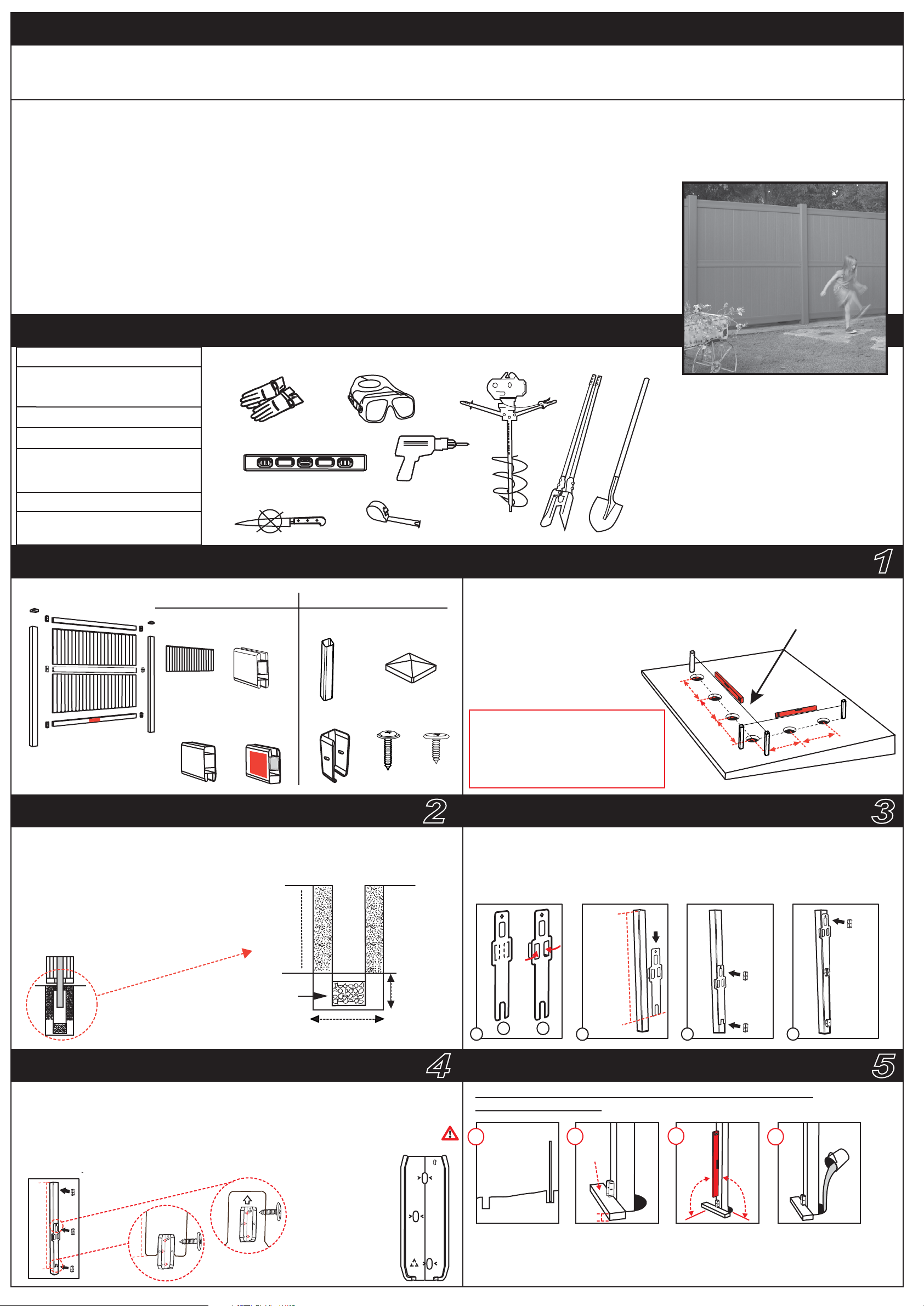
ASSEMBLY INSTRUCTIONS
SPRINGFIELD 6X6
cat : 555519
item : EN-V1
IMPORTANT: You must read these instructions carefully before you start to assemble this fence. Please carry out the steps in the order set out in these instructions. Keep these instructions
in a safe place for future reference.
GENERAL INFORMATION: The Keter Fence is easy to install. We incorporate methods and procedures used by professional installers to guide you through to the successful
completion of your fence.
GENERAL ADVICE: This is a 2 person assembly job. If it is a property line fence, you will want to confirm your property lines
before ordering your fence.The component parts should be checked and laid out in an orderly way, close at hand. Keep all small parts
(screws, etc.) in a bowl so that they do not get lost.
Please keep the tracking number which appears on the box, and refer to this number when calling the service office for questions or complaints.
CARE & MAINTENANCE: When your fence needs a clean, use a mild detergent solution and rinse with cold clean water.
DO NOT use acetone, abrasive cleaners or other special detergents to clean the fence.
For general support and replacement parts, please contact:
US: # 1-888-374-4262
Canada: # 1-800-661-6721
UK: # 0121-5060008
Other European Countries: # 31-1612-28301
String line
Post hole digger / power auger
www.keter.com
TOOLS & MATERIALS
Mallet
Work shoes
4 timber stakes
2”x 2”x24” (5cm x 5cm x 60cm)
Concrete / dry mix
PARTS & DIMENSIONS
PANEL
(x2)
TOP
RAIL (x1)
PANEL KIT
MIDDLE
RAILS (x1)
BOTTOM
RAIL (x1)
(x2)
(x6)
fcb
u
s35 (x12)
POST
BRACKET
POST KIT
35mm
POST
CAP (x1)
s18b (x18)
15mm
PROJECT PLANNING
1. Stake out fence from beginning to end.
2. Estimate the levelness of the ground.
3. Start at the highest side of the fence line!
4. Dig holes under the post line. Make sure
the distance between the hole centers is 6'
(1.82m).
For fence sections less than the
standard 6' (1.82m) center-to-center,
simply cut the rails and fence to size
using a power saw with a reinforced
metal blade.
(1.82 m)
6’
(1.82 m)
6’
(1.82 m)
1
String/fence line to show
horizontal accuracy.
6’
6’ (1.82 m)
6’ (1.82 m)
GENERAL ADVICE ON POST HOLES POSITIONING GUIDE
Use a post hole digger, power auger, or shovel to dig a hole 12” (30 cm) in diameter
and 30” (75 cm) deep. Add 6” (15 cm) of gravel
for post drainage. Insert the post in the center
of the post hole. Level the post and press it
firmly into the hole. Fill the remainder of the hole
with concrete according to the manufacturer's
instructions.
Gravel to reduce
frost heave
hole depth
24” (60 cm)
2
6” (15 cm)
below frost
line
A. Fold the positioning guide wings.
B. Positioning guide should be placed 68” (172 cm) from the top of the post.
C. Attach the positioning guide to the post as shown.
D. Place the bracket within the positioning guide hole.
POST TOP
68” (172cm)
Hole diameter 12” (30 cm)
1
A
BRACKETS ASSEMBLY FIXING FIRST POST
1. Attach three rail brackets (fcb) to one side of the post.
2. Do not assemble brackets on both sides of the post.
3. Place the positioning guide 68”(172 cm) from the top of the post, then place the bracket.
4. Locate all bracket screws (s18b) in the center of the elongated holes on the
bracket for expansion and contraction. The lip of the bracket should be at the bottom.
Top of
bracket
(X3)
fcb
4
Place the first post in the hole, checking that it satisfies ALL the following conditions:
HIGHEST GROUND POINT
A
up
GROUND
68” (172cm)
68” (172cm)
(X3)
A. Position the first post at the highest ground point of the fence line!
B. Place 2” (5cm) timbers under the bracket to maintain the gap between the fence and the ground.
C. Check the VERTICAL angle in two directions.
D. Use dry or ready-mix concrete and let it dry for 10 minutes.
2
B
B
TIMBER
2”
(5 cm)
HEIGHT
3
C
D
5
C
VERTICAL
o
90
Builder's
level.
o
90
ADD CONCRETE
D
Page 2

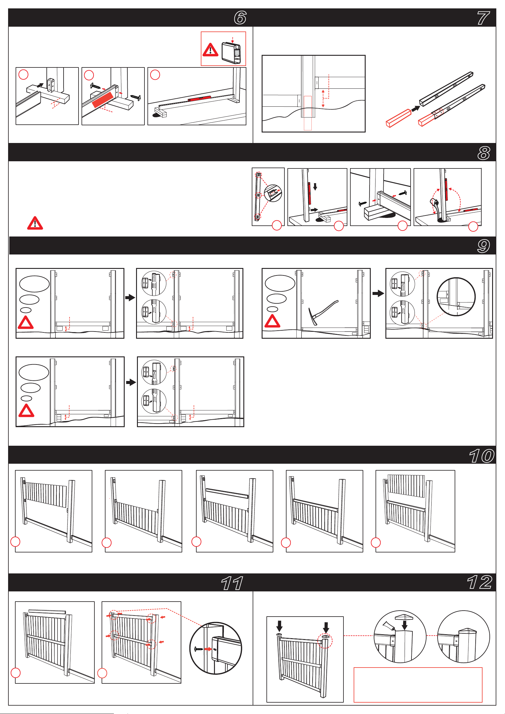
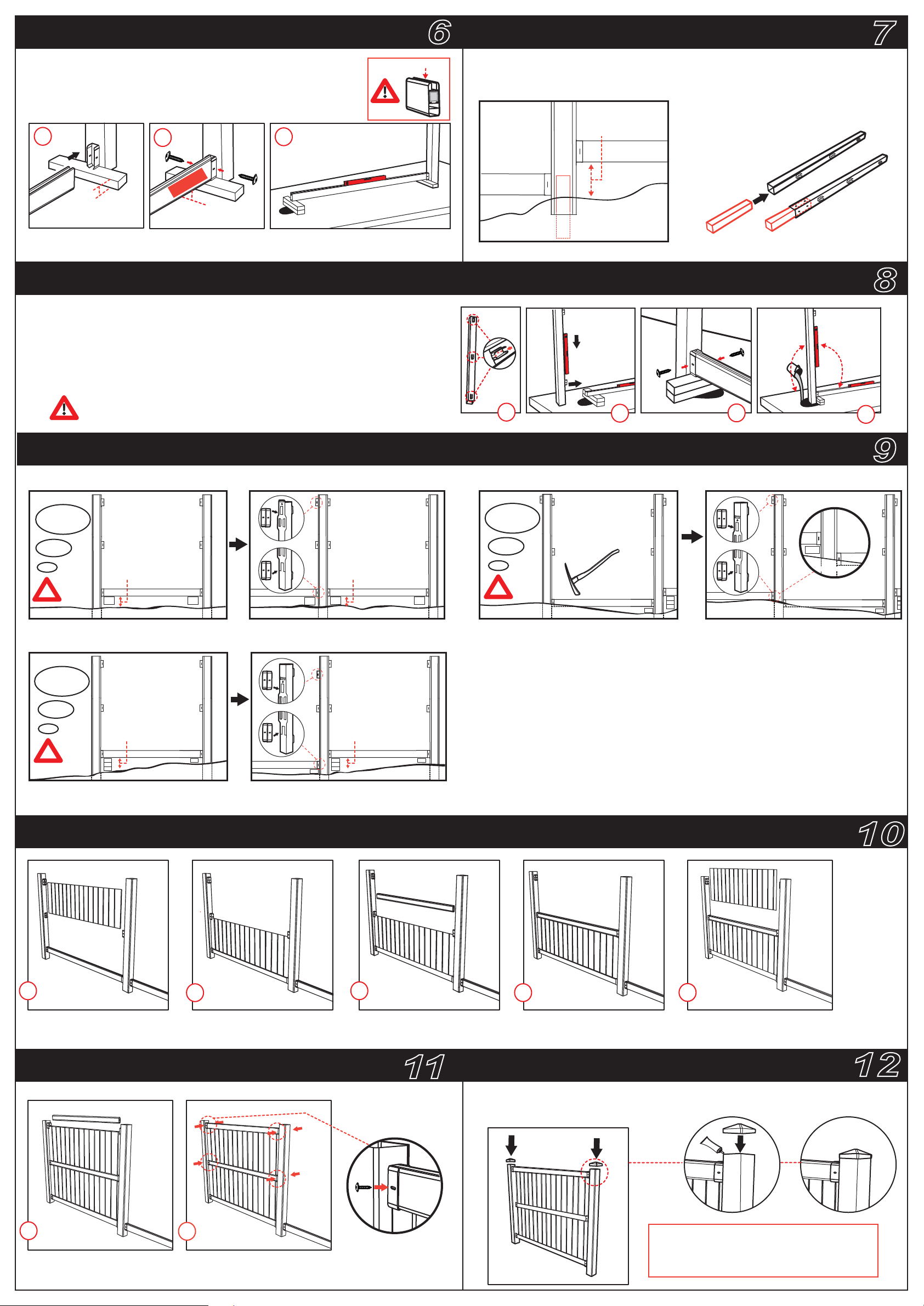
FIXING THE FIRST RAIL
6
EXTENDING THE POST
7
1. Place the lower rail in position.
2. Fix the rail to the post with 2 screws (s35), through the bracket
holes.
3. Level the rail horizontally. Use timber to help you.
1
2”
(5 cm)
Make sure the rail is horizontally level, at a 90° angle to the second post.
2
BOTTOM
2”
(5 cm)
3
This side up
The post must be cast at least 12“ (30 cm) in the ground. If you have a slope that is
over 12“ (30 cm), you must extend the post with timber as shown.
Use 4”/4”/24” (11/11/60 cm timber).
Fix with 8 screws.
FIXING THE SECOND POST (Take into account the level – downward or upward slope)
1. Attach three brackets to the post using the positioning guide.
2. Place the post in the hole.
3. Fix the post to the rail with 2 screws (s35) through the bracket holes.
4. Add dry or ready mix concrete. Allow concrete to set for 10-15 minutes.
up
12”-20“ (
30-50cm)
GROUND
90
8
o
90
o
Check that the rail is level and that the post is vertical from both sides.
LEVEL, DOWNWARD SLOPE & UPWARD SLOPE
Position the brackets on the empty side of the post, considering the 3 following options:
option 1
2nd post
2”-6” (5cm-15cm)
?
If the distance is 2”-6” (5-15cm), place the positioning guide 4” (10cm) from the ground and fix
the brackets with 3 (s18b) screws each.
option 2
Level
GROUND
Downward slope
1st post
2nd post
2”-6” (5cm-15cm)
GROUND
1st post
1
2
3
4
9
option 3
?
GROUND GROUND
In the case of an upward slope, connect the brackets 2" (5cm) up, and/or position the
new post lower while digging a trench for the rail.
Use the positioning guide to make sure that the upper bracket on the left side is
not over the top of the post.
Upward slope
3th post
2nd post
3th post
GROUND
2nd post
2nd post
2”-6” (5cm-15cm)
?
GROUND
If the distance is more than 6" (15cm), place the lower bracket 2" (5cm) from the ground
using 3 (s18b) screws. Fix the second bracket with 3 (s18b) screws using the positioning guide.
1st post
2nd post
2”-6” (5cm-15cm)
GROUND
1st post
INSTALLING A FENCE SECTION
1
Slot the first panel
into the bottom rail.
2
Make sure the panel goes
into the brackets.
3
Assemble the second rail
on top of the panel.
4
Make sure the rail goes
into the brackets.
10
5
Slot the the second
panel into the middle rail.
INSTALLING A FENCE SECTION
6
Assemble the upper rail on
top of the second panel.
7
Using screws (s35), fix the
upper and middle rails to the brackets.
11
(X2)
SCREW FROM
BOTH SIDES
ATTACH POST CAPS
1. Press caps down on post top.
2. You can secure the caps with silicone.
12
silicon
For fence sections that are less than the standard
6‘ (182 cm) center-to-center, simply cut the rails
and the fence panels to size, using a power saw.
Page 3

INSTRUCCIONES DE ENSAMBLADO
SPRINGFIELD 6X6
cat : 555519
IMPORTANTE: debe leer estas instrucciones con atención antes de intentar armar esta cerca.
Siga estos pasos en el orden que se indica en las instrucciones, las cuales deberá guardar en un lugar seguro, para su futura referencia.
INFORMACIÓN GENERAL: la cerca KETER es fácil de instalar. Incorporamos métodos y procedimientos
empleados por instaladores profesionales para guiarlo mientras completa correctamente el armado de su cerca.
CONSEJOS GENERALES: esta tarea de armado requiere la intervención de 2 personas.
Si se trata de una cerca para delimitar una propiedad, le conviene confirmar cuáles son los límites de la misma antes de pedir su cerca.
Las partes componentes deben ser verificadas y tendidas en forma ordenada y debe tenerlas a mano.
Mantenga todas las partes pequeñas (tornillos etc.) en un recipiente, para no perderlos.
Conserve el número de guía [tracking number] que aparece en la caja y remítase a este número cuando llame a la oficina de servicio para hacer preguntas o reclamos.
CUIDADOS Y MANTENIMIENTO: cuando tenga que limpiar su cerca, utilice una solución detergente suave y enjuáguela con agua limpia y fría.
NO use acetona, limpiadores abrasivos u otros detergentes especiales para limpiar la puerta.
Para solicitar soporte en general y partes de reemplazo, comuníquese con el centro de atención al cliente de Accent Home Products:
EE. UU.: 1-888-374-4262
Canadá: 1-800-661-6721
Reino Unido: 0121-5060008
Otros países europeos: 31-1612-28301
Cordel
Taladro perforador / taladro de
tierra mecánico
www.keter.com
HERRAMIENTAS Y MATERIALES
item : ES-V1
Maza
Calzado de seguridad
4 maderos
2”x 2”x 24” (5 cm x 5 cm x 60 cm)
Cemento/mezcla seca
PARTES Y DIMENSIÓN
KIT DEL PANEL
PANEL
(x2)
BARANDAS
SUPERIOR
(x1)
BARANDAS
INTERMEDIAS
(x1)
BARANDAS
E INFERIOR
(x1)
KIT DEL POSTE
(x2)
(x6)
fcb
u
s35 (x12)
35 mm
POSTE
MÉNSULA
s18b (x18)
15mm
TAPA DEL
POSTE (x1)
PLANIFICACIÓN DEL PROYECTO
1. Delimite la cerca del principio al fin.
2. Calcule el nivel del suelo.
3. Comience por el lateral más elevado de la
línea de la cerca.
4. Cave un pozo debajo de la línea del poste.
Asegúrese de que la distancia entre
los centros de los agujeros
sea de 6’ (1,82 m).
Para aquellas secciones de la cerca que
sean más pequeñas que lo convencional,
es decir, menores a 6’ (182 cm) de centro
a centro, simplemente corte las barandas
y la cerca al tamaño adecuado, con una
sierra eléctrica (utilice una hoja metálica).
(1,82 m)
6’
(1,82 m)
6’
(1,82 m)
6’
1
Cordel / línea de la cerca
para demostrar la
precisión horizontal
6’ (1,82 m)
6’ (1,82 m)
RECOMENDACIONES GENERALES SOBRE
LOS POZOS PARA LOS POSTES
2
Con un taladro perforador, un taladro de tierra mecánico o una pala, cave un pozo de
12” (30 cm) de diámetro y 30” (75 cm) de
profundidad. Agregue 6” (15 cm) de grava
para el drenaje del pozo. Inserte el poste en el
centro del mismo. Nivele el poste y comprímalo
con firmeza dentro del pozo. Llene lo que resta
del pozo con cemento, de acuerdo con las
instrucciones de fábrica.
Profundidad del
pozo 24” (60 cm)
6” (15 cm)
GUÍA DE POSICIONAMIENTO
A. Doble las aletas de la guía de posicionamiento.
B. La guía de posicionamiento debe colocarse a 68” (172 cm) de la parte
superior del poste.
C. Coloque la guía de posicionamiento en el poste, tal como se muestra.
D. Coloque la ménsula dentro del agujero de la guía de posicionamiento.
PARTE
SUPERIOR
DEL POSTE
debajo de la
Grava para reducir los
DAÑOS por heladas
línea de la
helada
68” (172 cm)
Diámetro del pozo
12” (30 cm)
MONTAJE DE LAS MÉNSULAS FIJACIÓN DEL PRIMER POSTE
1. Coloque las tres ménsulas de las barandas (fcb) en un lado de los postes.
2. No coloque las ménsulas en ambos lados del poste.
3. Coloque la guía de posicionamiento a 68” (172 cm) de la parte superior
del poste y luego coloque la ménsula.
4. Sitúe todos los tornillos s18b de las ménsulas en el centro de los orificios alargados
de la ménsula, para la expansión y contracción. El reborde de la ménsula debe estar
en la base.
4
Parte superior
de la ménsula
fcb
up
Coloque el primer poste en el pozo, constatando que satisfaga TODAS las condiciones
mencionadas a continuación:
1
A
Punto más alto del suelo
A
2
B
B
MADERO
ALTURA
C
VERTICAL
C
Nivel
D
D
3
5
AGREGAR CEMENTO
68” (172 cm)
68” (172)
(X3)
(X3)
o
90
SUELO
A. Ubique el primer poste en el punto más alto del suelo de la línea de la cerca.
B. Coloque los maderos de 5 cm debajo de la ménsula; mantenga la separación entre la cerca y el suelo.
C. Revise la VERTICALIDAD en ambas direcciones.
D. Utilice cemento o mezcla seca y DÉJELO SECAR durante 10 minutos.
2”
(5 cm)
o
90
Page 4

FIJACIÓN DE LA PRIMERA BARANDA
6
EXTENSIÓN DEL POSTE
7
1. Coloque la baranda inferior en su posición.
2. Fije la baranda al poste con 2 tornillos s35, a través de los orificios de
la ménsula.
3. Nivele la baranda horizontalmente, utilizando un madero como ayuda.
1
2”
(5 cm)
Asegúrese de que la baranda esté nivelada horizontalmente a 90º respecto del segundo poste.
2
BOTTOM
2”
(5 cm)
3
Este lado hacia arriba
El poste debe colocarse al menos a 12“ (30 cm) en el suelo. Si usted tiene una pendiente
mayor de 12“ (30 cm) debe extender el poste con el madero tal como se muestra.
Utilice un madero de 4”/4”/24” (11/11/60 cm)
Fije con el tornillo 8.
12”-20“ (
30-50 cm)
SUELO
FIJACIÓN DEL SEGUNDO POSTE (tenga en cuenta el nivel y la pendiente ascendente y descendente)
1. Coloque las tres ménsulas en el poste, usando la guía de posicionamiento.
2. Ubique el poste en el pozo.
3. Fíjelo a la baranda, con 2 tornillos (s35), a través de los agujeros de la ménsula.
4. Agregue cemento o mezcla seca. Espere unos 10-15 minutos hasta que el
cemento se endurezca.
Verifique que la baranda esté nivelada y que el poste
esté vertical en ambas direcciones.
up
1
2
3
90
o
90
8
o
4
NIVEL, PENDIENTE DESCENDENTE Y PENDIENTE ASCENDENTE
Ubique las ménsulas del lado vacío (en la dirección de continuación) del poste, considerando las siguientes 3 opciones:
Opción 1
2.º poste
2”-6” (5 cm-15 cm)
?
Si es de 5-15 cm coloque la guía de posicionamiento a 10 cm del suelo y fije las ménsulas
con 3 tornillos (s18b) para cada una.
Opción 2
2.º poste
2”-6” (5 cm-15 cm)
?
Nivel
SUELO
Pendiente
descendente
1.º poste
1.º poste
2.º poste
2”-6” (5 cm-15 cm)
SUELO
2.º poste
2”-6” (5 cm-15 cm)
1.º poste
1.º poste
Opción 3
Pendiente
ascendente
3.º poste
?
SUELO SUELO
En caso de una pendiente ascendente, conecte las ménsulas a 2” (5 cm) arriba y/o
ubique el nuevo poste más abajo, mientras cava una zanja para la baranda.
Asegúrese (usando la guía de posicionamiento) de que la ménsula superior del lado
izquierdo no quede fuera de la partes superior del poste.
2.º poste
3.º poste
SUELO
9
2.º poste
SUELO
Si la distancia es mayor que 6” (15 cm) coloque la ménsula inferior a 2” (5 cm) del suelo
y utilice 3 tornillos (s18b). Fije la segunda ménsula usando la guía de posicionamiento. Utilice 3 tornillos (s18b).
SUELO
INSTALACIÓN DE LA SECCIÓN DE LA CERCA
1
Ensamble el primer panel
en la baranda inferior.
2
Asegúrese de que el panel
entre en las ménsulas.
INSTALACIÓN DE LA SECCIÓN DE LA CERCA
3
Ensamble la segunda baranda
sobre la parte superior del panel.
11
4
Asegúrese de que la baranda
entre en las ménsulas.
COLOCACIÓN DE LAS TAPAS DE LOS POSTES
10
5
Arme el segundo panel en la
baranda intermedia.
12
6
Coloque la baranda superior
sobre el segundo panel.
(x2)
7
ATORNILLE DESDE
Utilizando los tornillos (s35),
fije las barandas superior y central a las ménsulas.
AMBOS LADOS
1. Presione las tapas hacia abajo, sobre la parte superior del poste.
2. Puede fijar las tapas con silicio.
silcion
Para las secciones de la cerca con una medida inferior a la
estándar, que es de 6’ (182 cm) de centro a centro, simplemente corte las barandas al tamaño y los paneles de la
cerca, con una sierra eléctrica.
Page 5

INSTRUCTIONS DE MONTAGE
SPRINGFIELD 6X6
cat : 555519
IMPORTANT: Veuillez lire ces instructions attentivement avant de commencer à monter cette clôture.
Procédez aux étapes ci-dessous dans l'ordre indiqué. Conservez ces instructions dans un lieu sûr pour toute référence ultérieure.
INFORMATIONS GÉNÉRALES: La clôture Keter est facile à installer. Les instructions réunissent les méthodes et procédures utilisées par des installateurs
professionnels, afin de vous guider et de vous aider à réussir l'installation de votre clôture.
CONSIGNES GÉNÉRALES: Le montage doit être effectué par 2 personnes. S'il s'agit d'une clôture délimitant une propriété,
veuillez confirmer la limite de votre propriété avant de commander votre clôture. Vérifiez les composants et disposez-les de manière ordonnée
tout en les gardant à portée de mains. Conservez les petites pièces (vis, etc.) dans un bol, afin de ne pas les égarer.
Veuillez conserver le numéro de référence qui figure sur la boîte d'emballage et vous y référer lorsque vous contactez notre service clientèle
concernant toutes questions ou réclamations.
ENTRETIEN: Pour nettoyer la clôture, utilisez une solution détergente douce et rincez à l'eau froide. NE PAS UTILISER d'acétone,
ni de nettoyants abrasifs ou d'autres détergents spéciaux pour nettoyer la clôture.
Vous pouvez contacter notre service clientèle ou obtenir des pièces de rechange aux coordonnées suivantes :
U.S.A: 1-888-374-4262
Canada: 1-800-661-6721
Royaume-Uni: 0121-5060008
Autre pays européen: 31-1612-28301
Cordeau
Tarière / Tarière à moteur
www.keter.com
OUTILS ET MATÉRIELS
Article : FR-V1
Maillet
Chaussures de travail
4 piquets de bois 5x5x60 cm
(2"x2"x24")
Béton / Mélange à sec
COMPOSANTS ET DIMENSIONS
KIT PANNEAU
PANNEAU
(x2)
TRAVERSE
SUPÉRIEURE
(x1)
TRAVERSE
MÉDIANE (x1)
TRAVERSE
INFÉRIEURE
(x1)
KIT POTEAU
POTEAU
(x2)
CROCHET
(x6)
fcb
u
s35 (x12)
35 mm
CHAPEAU DE
POTEAU (x1)
s18b (x18)
15mm
PLANIFICATION DU PROJET
1. Surveillez la clôture du début à la fin.
2. Estimez le niveau du sol.
3. Commencez du côté le plus haut de la
ligne de clôture !
4. Creusez un trou sous la ligne des poteaux.
Assurez-vous que la distance entre les
centres des trous est de 182 cm (6').
(1.82 m)
6’
Pour les sections de clôture dont la taille
est inférieure à la distance entre centres
standard de 182 cm (6'), coupez
simplement les traverses et les
panneaux de clôture aux dimensions
souhaitées, à l’aide d’une scie électrique
(utilisez une lame en métal).
(1.82 m)
6’
(1.82 m)
6’
1
Cordeau / ligne de clôture
pour illustrer la précision
horizontale
6’ (1.82 m)
6’ (1.82 m)
CONSIGNES GÉNÉRALES CONCERNANT
LES TROUS DE POTEAUX
À l’aide d’une tarière, d’une tarière à moteur ou bien d’une simple pelle, creusez un trou de
30 cm (12") de diamètre et de 75 cm (30") de
profondeur. Ajoutez 15 cm (6") de gravier afin
d'évacuer l’eau. Insérez le poteau au centre du trou.
Mettez à niveau le poteau et enfoncez-le fermement
dans le trou. Remplissez le reste du trou avec du
béton, en suivant les instructions du fabriquant.
Profondeur du
trou : 60 cm (24")
Graviers pour réduire
le SOULÈVEMENT
dû au gel
2
15 cm (6")
sous le niveau
de gélivation
Diamètre du trou : 30 cm (12")
INSTALLATION DES CROCHETS INSTALLATION DU PREMIER POTEAU
1. Fixez 3 crochets de traverse (fcb) à l'un des côtés du poteau.
2. Ne pas fixer les crochets sur les deux côtés du poteau.
3. Placez le guide de positionnement à 172 cm (68") en partant du haut du poteau,
puis placez le crochet.
4. Placez les vis de crochets (s18b) au centre des trous élongés (sur le crochet) pour
permettre une expansion ou une réduction. La lèvre du crochet devrait être en bas.
fcb
4
Haut du
crochet
up
GUIDE DE POSITIONNEMENT
A. Pliez les ailes du guide de positionnement.
B. Placez le guide de positionnement à 172 cm (68") en partant du haut du poteau.
C. Fixez le guide de positionnement au poteau, comme indiqué sur l’image.
D. Placez le crochet dans le trou du guide de positionnement.
SOMMET
DU POTEAU
172 cm (68”)
1
A
Placez le premier poteau dans le trou en vérifiant TOUTES les conditions suivantes :
Point le plus haut du sol
A
2
B
B
PIQUET
HAUTEUR
C
VERTICAL
C
Niveau de
bâtisseur
D
AJOUTEZ DU BÉTON
D
3
5
172 cm (68”)
172 cm (68”)
(X3)
(X3)
o
90
SOL
A. Placez le premier poteau au point le plus haut du sol de la ligne de clôture !
B. Placez des piquets de 5cm (2”) sous le crochet afin de maintenir l’écart entre la clôture et le sol.
C. Vérifiez l’ANGLE VERTICAL dans deux directions.
D. Utilisez du béton sec ou mélangé et LAISSEZ SÉCHER pendant 10 minutes.
5 cm
(2”)
o
90
Page 6

INSTALLATION DE LA PREMIÈRE TRAVERSE
1. Mettez la traverse inférieure en place.
2. Fixez la traverse au poteau à l’aide de 2 vis (s35), en passant
par les trous du crochet.
3. Mettez à niveau la traverse à l’horizontale. Utilisez un piquet de
bois pour la soutenir.
1
2
3
Haut
6
RALLONGER LE POTEAU
Le poteau doit être au moins enfoncé à 30 cm (12") dans le sol. Si la pente est
supérieure à 30 cm (12"), vous devez prolonger le poteau avec un piquet de bois
comme indiqué sur l’image.
Utilisez un piquet de 11/11/60 cm
(4" / 4" / 24") et fixez-le à l'aide de 8 vis.
7
30-50cm (12”-20”)
BOTTOM
5 cm
(2”)
Assurez-vous que la traverse est à niveau à l’horizontale et à un angle de 90°
par rapport au deuxième poteau.
5 cm
(2”)
SOL
INSTALLATION DU POTEAU SUIVANT (Tenez compte du niveau, des pentes descendantes et ascendantes)
1. Connectez 3 crochets à un poteau en utilisant le guide de positionnement.
2. Placez le poteau dans le trou.
3. Fixez le poteau à la traverse à l’aide de deux vis (s35), à travers les trous des crochets.
4. Ajoutez du béton sec ou mélangé et laissez sécher pendant 10 à 15 minutes.
Vérifiez que la traverse est à niveau et que le poteau est vertical
dans les deux directions !
up
1
2
3
90
o
NIVEAU, PENTES DESCENDANTES ET ASCENDANTES
Placez les crochets du côté vide (dans le prolongement) du poteau, en considérant les 3 options suivantes :
90
o
8
4
9
option 1
2ème poteau
5 cm-15 cm (2”- 6”)
?
Si la distance est de 5 à 15 cm (2”-6"), placez le guide de positionnement à 10 cm (4”) du sol
et fixez les crochets. 3 vis (s18b) par crochet
option 2
2ème poteau
5 cm-15 cm (2”-6”)
?
Si la distance au sol est de plus de 15 cm (6"), placez le crochet inférieur à 5 cm (2") du sol.
Utilisez 3 vis (s18b) pour fixer le deuxième crochet en vous servant du guide de positionnement.
Niveau
SOL
Pente
descendante
SOL
1er poteau
1er poteau
2ème poteau
5 cm-15 cm (2”- 6”)
SOL
2ème poteau
5 cm-15 cm (2”-6”)
SOL
1er poteau
1er poteau
En cas de pente ascendante, connectez les crochets à 5 cm (2") de haut et/ou placer
le nouveau poteau plus bas, tout en creusant une tranchée pour la traverse.
Assurez-vous (à l'aide du guide de positionnement) que le crochet supérieur du côté
gauche ne dépasse pas du sommet du poteau.
option 3
Pente
ascendante
3ème poteau
?
SOL SOL
2ème poteau
3ème poteau
SOL
2ème poteau
INSTALLATION DES SECTIONS DE CLÔTURE
1
Insérez le premier panneau
dans la traverse inférieure.
2
Assurez-vous que le panneau
s’emboîte dans les crochets.
3
Fixez la traverse suivante
sur le panneau.
INSTALLATION DES SECTIONS DE CLÔTURE
11
4
Assurez-vous que la traverse
rentre bien dans les crochets.
5
Insérez le deuxième panneau
sur la traverse médiane.
INSTALLATION DES CHAPEAUX DE POTEAU
1. Fixez les chapeaux sur le haut du poteau, en pressant vers le bas.
2. Si nécessaire, ajoutez de la silicone.
silcion
10
12
6
Fixez la traverse supérieure
sur le deuxième panneau.
(X2)
7
VISSEZ DES
À l'aide des vis (s18b), fixez
les traverses supérieure et médiane aux crochets.
DEUX CÔTÉS
Pour les sections de clôtures dont la taille est inférieure
à la distance entre centres standard de 182 cm (6’),
coupez simplement les traverses et les panneaux de
clôture à l’aide d’une scie électrique.
Page 7

MONTAGEANLEITUNG
SPRINGFIELD 6X6
cat : 555519
Artikelnr: DE-V01
WICHTIG: Lesen Sie diese Anweisungen genau, bevor Sie mit der Montage des Zauns beginnen. Bitte führen Sie die folgenden Schritte in der hier beschriebenen Reihenfolge aus.
Bewahren Sie diese Anleitung zum späteren Nachschlagen an einem sicheren Ort auf.
ALLGEMEINE INFORMATIONEN: Der Keter Zaun ist einfach zu montieren. Wir verwenden Methoden und Vorgänge, die von professionellen Handwerkern verwendet werden,
um Sie erfolgreich durch die Montageanleitung Ihres Zauns zu leiten.
ALLGEMEINE HINWEISE: Für den Zusammenbau werden 2 Personen benötigt. Falls es sich um einen Zaun zur
Grundstücksabgrenzung handelt, sollten Sie die Grundstücksgrenzen überprüfen, bevor Sie den Zaun bestellen. Die Bauteile sollten
überprüft und systematisch und griffbereit ausgelegt werden. Geben Sie alle Kleinteile (z.B. Schrauben etc.) in eine Schüssel, so dass nichts
verloren geht. Bitte bewahren Sie die Frachtnummer, die auf dem Karton angegeben ist, auf, um diese Nummer angeben zu können, falls Sie
sich für Fragen oder Beschwerden an das Servicebüro wenden sollten.
PFLEGE & INSTANDHALTUNG: Wenn Ihr Zaun gesäubert werden muss, benutzen Sie eine milde Reinigungslösung
und spülen Sie den Zaun mit kaltem, klarem Wasser ab. Benutzen Sie zur Reinigung des Zauns NIEMALS Aceton, aggressive Reinigungsmittel
oder andere Spezialreiniger. Für jegliche Unterstützung und Ersatzteile wenden Sie sich bitte an:
USA: 1-888-374-4262
Canada: 1-800-661-6721
GB: 0121-5060008
Andere europäische Länder: (+) 31-1612-28301
Schnur für gerade Zaunlinie
Pfosten-Lochbohrer/
Elektrischer Erdbohrer
WERKZEUG & MATERIALIEN
www.keter.com
www.keter.com
Holzhammer
Arbeitsschuhe
4 Holzbalken
5cm x 5cm x 60cm
Beton / Trockenspritzbeton
TEILE & ABMESSUNGEN
PLATTEN-BAUSATZ
PLATTE
(x2)
LEISTE FÜR
OBERSEITE
(x1)
MITTELLEISTE
(x1)
LEISTE FÜR
UNTERSEITE
(x1)
PFOSTEN-BAUSATZ
PFOSTEN
(x2)
s35 (x12)
35mm
s18b (x18)
15mm
PFOSTENKAPPE
HALTEKLAMMER
(x6)
(x1)
PROJEKTPLANUNG
1
1. Stecken Sie den Verlauf des Zauns von Anfang bis zum Ende ab.
2. Schätzen Sie die Geländehöhe ab.
3. Beginnen Sie auf der höchsten Seite der Zaunlinie!
Die Schnur-/Zaunlinie
muss gerade sein.
4. Graben Sie unter der Pfostenmarkierung ein Loch.
Bitte stellen Sie sicher, dass der Abstand
zwischen den Lochmittelpunkten
1,82m beträgt.
fcb
u
Bei Zaunbereichen, die eine kleinere
Abmessung von Mittelpunkt zu
Mittelpunkt aufweisen, als die
Standardabmessung von 182cm,
benutzen Sie einfach eine Motorsäge
(benutzen Sie ein Metallsägeblatt),
um die Leisten & die Zaunplatten auf
die richtige Größe zu stutzen.
1,82 m
1,82 m
1,82 m
1,82 m
1,82 m
ALLGEMEINE HINWEISE ZU PFOSTENLÖCHERN FÜHRUNGSTEIL FÜR MONTAGE
Graben Sie ein Loch von 30cm Durchmesser und 75cm Tiefe, indem Sie einen PfostenLochbohrer, einen elektrischen Erdbohrer oder einfach eine Schaufel benutzen.
Füllen Sie dieses Loch mit 15cm Kies auf, um den Abfluss von Regenwasser
sicherzustellen. Stellen Sie den Pfosten in die
2
A. Schließen Sie zur Zaunmontage die Flügel des Führungsteils.
B. Das Führungsteil sollte 172cm von der Pfostenspitze entfernt positioniert werden.
C. Bringen Sie das Führungsteil, wie in der Abbildung gezeigt, an den Pfosten an.
D. Verschrauben Sie die Halteklammer im Loch des Führungsteils.
Mitte des Loches. Drücken Sie ihn fest in den
Boden und sorgen Sie dafür, dass er gerade steht.
Füllen Sie nun das verbleibende Loch mit Beton
den Anweisungen des Herstellers folgend auf.
60cm
Pfostenspitze
Lochtiefe
15cm
Kies, um den FrostHUB zu vermindern
Lochdurchmesser 30cm
ANBRINGEN DER HALTEKLAMMERN BEFESTIGUNG DES ERSTEN PFOSTENS
1. Montieren Sie drei Leisten-Halteklammern an einer Seite der Pfosten.
2. Montieren Sie Halteklammern nicht an beiden Seiten der Pfosten.
3. Bringen Sie das Führungsteil 172cm von der Pfostenspitze gemessen an und
verschrauben Sie danach die Halteklammern.
4. Montieren Sie aufgrund von Materialausdehnung alle Schrauben (s18b) in
der Mitte der länglichen Löcher auf den Halteklammern. Der Rand jeder
Halteklammer sollte sich an der Unterseite befinden.
Unter der
Frosttiefe
4
Spitze der
Halteklammer
fcb
up
1
A
2
B
Platzieren Sie den ersten Pfosten in seinem Loch und überprüfen Sie, ob ALLE der
folgenden Bedingungen erfüllt sind:
Höchster Punkt des Geländes
A
Höhe
B
Holzbalken
172cm
C
Senkrecht
C
Wasserwaage
3
D
5
Beton hinzugeben
D
172cm
172cm
(x3)
(x3)
o
90
BODEN
A. Positionieren Sie den ersten Pfosten am höchsten Geländepunkt der Zaunlinie!
B. Positionieren Sie ein 5cm dickes Holzstück unter der Halteklammer. Bewahren Sie immer
diesen Abstand zwischen Zaun und Boden.
C. Überprüfen Sie den SENKRECHTEN 90º Winkel in zwei Richtungen.
D. Benutzen Sie Trocken- oder Mischbeton. Lassen Sie diesen 10 Minuten TROCKNEN.
5 cm
o
90
Page 8
MONTIEREN DER ERSTEN HALTEKLAMMER
6
VERLÄNGERN DES PFOSTENS
7
1. Positionieren Sie die untere Leiste.
2. Befestigen Sie die Leiste mit 2 Schrauben (s35) durch die
Halteklammerlöcher an den Pfosten.
3. Richten Sie die Leiste horizontal aus, indem Sie einen Holzbalken
zur Hilfe nehmen.
1
5 cm
Stellen Sie sicher, dass die Leiste horizontal ausgerichtet ist und bezüglich des
zweiten Pfostens einen 90° Winkel einhält.
2
BOTTOM
5 cm
3
Diese Seite nach oben.
MONTIEREN DES ZWEITEN PFOSTENS (beachten Sie Ebene, Gefälle, Steigung)
1. Bringen Sie drei Halteklammern am Pfosten an, indem Sie das Führungsteil
benutzen.
2. Stellen Sie den Pfosten in das Loch.
3. Befestigen Sie den Pfosten an der Leiste mit 2 Schrauben (s35) durch die
Halteklammerlöcher.
4. Fügen Sie nun Beton (Trocken- oder Mischbeton) in den verbleibenden
Zwischenraum hinzu. Lassen Sie den Beton 10-15 Minuten trocknen.
Stellen Sie sicher, dass die Leiste gerade ausgerichtet ist und
der Pfosten auf beiden Seiten vertikal ist!
Der Pfosten muss mindestens 30cm im Boden verankert sein und wenn Sie ein
Gefälle von mehr als 30cm haben, wie dargestellt, mit einem Holzbalken
verlängert werden.
Benutzen Sie 11/11/60cm Holzbalken
30-50cm
BODEN
up
1
2
3
90
o
90
o
4
8
EBENE, GEFÄLLE UND STEIGUNG
Positionieren Sie die Halteklammern an der leeren Seite des Pfostens (in fortlaufender Richtung). Beachten Sie die folgenden 3 Möglichkeiten:
Möglichkeit
1
?
Wenn die Höhendifferenz 5-15cm beträgt, positionieren Sie das Führungsteil 10cm vom
Boden entfernt und montieren Sie die Halteklammern mit jeweils 3 Schrauben (s18b).
Möglichkeit
2
?
Ebene Fläche
Zweiter Pfosten
5cm-15cm
BODEN
Gefälle
Zweiter Pfosten
5cm-15cm
Erster Pfosten
Erster Pfosten
Zweiter Pfosten
5cm-15cm
Zweiter Pfosten
5cm-15cm
BODEN
Erster Pfosten
Erster Pfosten
Möglichkeit
3
?
BODEN BODEN
Im Falle einer Steigung, müssen die Halteklammern 5cm höher angebracht
werden und/oder positionieren Sie den neuen Pfosten tiefer, indem Sie einen Graben
für die Leiste ausheben.
Stellen Sie sicher (indem Sie das Führungsteil verwenden), dass die obere
Halteklammer auf der linken Seite nicht über die Pfostenspitze ragt.
Dritter Pfosten
Steigung
Zweiter Pfosten
Dritter Pfosten
BODEN
9
Zweiter Pfosten
BODEN
Wenn die Höhendifferenz mehr als 15cm beträgt, positionieren Sie die untere Halteklammer 5cm vom Boden entfernt und verschrauben Sie diese mit 3 Schrauben (s18b).
Legen Sie das Führungsteil an die erste Halteklammer und montieren Sie die zweite und dritte Halteklammer jede mit 3 Schrauben (s18b) an die entsprechende Position.
BODEN
MONTIEREN DES ZAUNTEILS
1
Schieben Sie die erste
Platte in die Bodenleiste.
2
Stellen Sie sicher, dass die
Platte von den Halteklammern
gestützt wird.
MONTIEREN DES ZAUNTEILS
3
Montieren Sie die zweite
Leiste auf der Platte.
11
4
Stellen Sie sicher, dass
auch diese Mittelleiste von den
Halteklammern gestützt wird.
5
Befestigen Sie die zweite
Platte an der Mittelleiste.
PFOSTENKAPPEN ANBRINGEN
10
12
6
Montieren Sie die obere
Leiste auf der zweiten Platte.
7
Befestigen Sie beide Leisten
mit Hilfe der Schrauben s35.
(x2)
VON BEIDEN SEITEN
VERSCHRAUBEN
1. Drücken Sie die Kappen auf die Pfosten.
2. Sie können die Kappen mit Silikon befestigen.
silcion
Bei Zaunabschnitten, die eine kürzere Distanz von
Mittelpunkt zu Mittelpunkt aufweisen, als die
Standardabmessung von 182cm, benutzen Sie einfach
eine Motorsäge, um die Leisten & die Zaunplatten auf
die richtige Größe zu stutzen.
Page 9
ISTRUZIONI DI MONTAGGIO
RECINZIONE SPINGFIELD 6X6
cat : 555519
IMPORTANTE: Leggere attentamente queste istruzioni prima di iniziare ad assemblare la recinzione. Seguire queste procedure nell’ordine
indicato nelle istruzioni. Conservare queste istruzioni in un luogo sicuro per futuri riferimenti.
INFORMAZIONI GENERALI: La recinzione Keter è semplice da installare. I metodi e le procedure da noi adottate sono utilizzate
da installatori professionisti per guidarvi attraverso la giusta installazione della vostra recinzione.
SUGGERIMENTI GENERALI: Questo lavoro di assemblaggio va effettuato da 2 persone. Nel caso si tratti di una recinzione di
delimitazione della proprietà, bisognerà confermare i confini della proprietà prima di ordinare la recinzione.
Controllare le parti dei componenti e sistemarle in modo ordinato, a portata di mano. Conservare le parti piccole (viti, ecc.) in un contenitore onde
evitare di perderle.
Conservare il codice di spedizione indicato sulla scatola, facendo riferimento ad esso quando si contatta il servizio assistenza per domande o reclami.
PULIZIA E MANUTENZIONE: Per pulire la recinzione utilizzare una soluzione detergente leggera e risciacquare
con acqua fredda.
NON utilizzare acetone, detergenti abrasivi o altri detergenti particolari. Per assistenza generale e parti di ricambio, contattare:
USA: 1-888-374-4262
CDN.: 1-800-661-6721
GB: 0121-5060008
Altri paesi europei: (+) 31-1612-28301
Filo di corda
Trivella / trivella
a trasmissione di potenza
STRUMENTI E MATERIALI
www.keter.com
Articolo N.: IT-V1
Maglio
Scarpe da lavoro
4 paletti di legno squadrato
(5cm x 5cm x 60cm)
Calcestruzzo / malta
PARTI E DIMENSIONI
PANNELLO
(x2)
TRAVERSA
SUPERIORE
KIT PANNELLO
TRAVERSE
INTERMEDIE
(x1)
TRAVERSA
INFERIORE
(x1)
(x1)
PALO
(x2)
STAFFA
(x6)
fcb
u
KIT PALO
CALOTTA PROTETTIVA
PALO
(x1)
s35 (x12)
35mm
s18b (x18)
15mm
PIANIFICAZIONE PROGETTO
1. Delimitare la recinzione dal punto iniziale a quello finale.
2. Valutare il livellamento del terreno.
3. Partire dalla parte più alta della linea della recinzione!
4. Scavare delle buche sotto la linea del palo. Accertarsi che la
distanza tra i centri delle buche sia di 1,82m.
1,82 m
1,82 m
Per i settori di recinzione di dimensione
inferiore alla misura standard di 1,82m
da centro a centro, basta semplicemente
adattarli tagliando letraverse e la
recinzione con l’ausilio di una sega elettrica
con lama metallica rinforzata.
1,82 m
1
Linea di delimitazione/
della recinzione che
mostra la precisione in
orizzontale
1,82 m
1,82 m
SUGGERIMENTI GENERALI PER LE BUCHE DEL PALO GUIDA DI POSIZIONAMENTO
Con una trivella, una trivella a trasmissione di potenza, o una pala meccanica scavare
una buca di 30cm di diametro e 75cm di profondità. Aggiungere 15cm di ghiaia per il
drenaggio del palo. Inserire il palo al centro della buca.
Livellare il palo e spingerlo con forza all’interno.
2
A. Chiudere le alette laterali della guida di posizionamento.
B. Posizionare la guida a 172cm dalla parte superiore del palo.
C. Fissare la guida sul palo come mostrato.
D. Inserire la staffa nel foro della guida.
Riempire il resto della buca con calcestruzzo
secondo le istruzioni del produttore.
della buca
60cm profondità
Cospargere di ghiaia per
ridurre il rigonfiamento del
suolo causato dal gelo
Diametro buca 30cm
MONTAGGIO DELLE STAFFE INSERIMENTO DEL PRIMO PALO
1. Fissare tre staffe guida (fcb) su un lato del palo.
2. Non montare le staffe su entrambi i lati.
3. Posizionare la guida a 172cm dalla parte superiore del palo quindi fissare la staffa.
4. Stabilire la posizione delle viti (s18b) della staffa al centro dei fori oblunghi sulla
staffa stessa per estensione e restringimento.
Il bordo della staffa deve trovarsi nella parte inferiore.
15cm sotto
la linea di
congelamento
4
Parte
superiore
della staffa
fcb
up
1
A
2
Posizionare il primo palo nella buca, verificando che siano soddisfatte
TUTTE queste condizioni:
PUNTO PIÙ ALTO DEL TERRENO
A
PARTE
SUPERIORE
B
ALTEZZA
B
TRAVE IN
LEGNO
DEL PALO
172cm
C
VERTICALE
C
Livello del
produttore
3
D
5
AGGIUNTA DI CALCESTRUZZO
D
172cm
172cm
(x3)
(x3)
o
90
TERRENO
A. Posizionare il primo palo nel punto più alto del terreno della linea della recinzione!
B. Posizionare le travi in legno da 5cm sotto la staffa in modo da sostenere il vuoto tra la
recinzione e il terreno.
C. Controllare l’angolazione VERTICALE nelle due direzioni.
D. Utilizzare della malta o calcestruzzo preconfezionato e lasciarlo asciugare per 10 minuti.
5cm
o
90
Page 10
FISSAGGIO DELLA PRIMA TRAVERSA
6
PROLUNGAMENTO DEL PALO
7
1. Mettere la traversa inferiore in posizione.
2. Fissare la traversa al palo con 2 viti (s35), attraverso i fori della
staffa.
3. Livellare la traversa orizzontalmente. Per agevolare l’operazione
utilizzare il legno squadrato.
1
5cm
2
BOTTOM
5cm
3
Lato verso l’alto
Il palo dev’essere incastrato nel terreno a una profondità di almeno 30cm.
Se la pendenza è superiore a 30cm, prolungare il palo nel terreno con il legno
squadrato come mostrato.
Utilizzare un legno squadrato da 11/11/60cm.
Fissare con 8 viti.
30-50cm
TERRENO
Verificare che la traversa sia posta in livello orizzontale, con un angolo di 90° rispetto
al secondo palo.
FISSAGGIO DEL SECONDO PALO (Tenere in considerazione il livello – pendenza verso il basso o verso l’alto)
1. Fissare al palo tre staffe con l’ausilio della guida di posizionamento.
2. Posizionare il palo all’interno della buca.
3. Fissare il palo alla traversa con 2 viti (s35) attraverso i fori della staffa.
4. Aggiungere della malta o del calcestruzzo preconfezionato. Lasciare il
calcestruzzo in posa per 10-15 minuti.
up
90
8
o
90
o
Verificare che la traversa sia a livello e che il palo sia in verticale
da entrambi i lati.
LIVELLO, PENDENZA VERSO IL BASSO E VERSO L’ALTO
Posizionare le staffe sulla parte vuota del palo, tenendo in considerazione queste 3 opzioni:
opzione 1
Livello
2° palo
5cm-15cm
?
TERRENO
Se la distanza è pari a 5-15cm, sistemare la guida di posizionamento a 10cm dal terreno
e fissare le staffe con 3 viti (s18b) ciascuna.
opzione 2
Pendenza verso
il basso
1° palo
2° palo
5cm-15cm
TERRENO
1° palo
1
2
3
4
9
opzione 3
?
TERRENO
In caso di pendenza verso l’alto, congiungere le staffe da 5cm, e/o posizionare il nuovo
palo in basso scavando una fossa per la traversa.
Con la guida di posizionamento accertarsi che la staffa superiore posta sul lato sinistro
non fuoriesca oltre la parte superiore del palo.
Pendenza verso
l’alto
3° palo
2° palo
TERRENO
3° palo
BODEN
2° palo
2° palo
5cm-15cm
?
TERRENO
Se la distanza è superiore a 15cm, sistemare la staffa inferiore a 5cm dal terreno utilizzando 3 viti (s18b).
Fissare la seconda staffa con 3 viti (s18b) tramite la guida di posizionamento.
1° palo
2° palo
5cm-15cm
1° palo
TERRENO
MONTAGGIO DI UN SETTORE DELLA RECINZIONE
1
Inserire il primo pannello nella
traversa inferiore.
2
Verificare che il pannello sia
all’interno delle staffe.
3
Montare la seconda traversa
sulla parte superiore del pannello.
4
Verificare che la traversa sia
all’interno delle staffe.
10
5
Inserire il secondo pannello nella
traversa intermedia.
MONTAGGIO DI UN SETTORE DELLA RECINZIONE
(x2)
6
Montare la traversa superiore
sulla cima del secondo pannello.
7
AVVITARE DA
Utilizzando le viti s35, fissare
la traversa superiore e quella centrale alle staffe.
ENTRAMBI I LATI
11
FISSARE LE CALOTTE PROTETTIVE AL PALO
1. Premere giù le calotte protettive sulla sommità del palo.
2. Fissare le calotte con del silicone.
silcion
Per i settori di recinzione di dimensione inferiore alla misura
standard di 182cm da centro a centro, basta semplicemente
adattarli tagliando le traverse e i pannelli della recinzione, con
l’ausilio di una sega elettrica.
12
 Loading...