

Page 1
GATE 4X6
ASSEMBLY INSTRUCTIONS | INSTRUCCIONES DE MONTAJE | CONSIGNES DE MONTAGE | MONTAGEANLEITUNG |
ISTRUZIONI D’ASSEMBL AGGIO |
WWW.KETER.COM
Thank you for your purchase of the Keter fence,
WARRANTY
ACTIVATION
In order to activate your warranty, please enter
www.ket er.com , and ll in the form under
warranty activation.
IF THERE ARE MISSING OR BROKEN PARTS, PLEASE DO NOT RETURN THE PRODUCT TO THE STORE.
EN
Please log onto our website, or contact Customer Service at:
SI HUBIERA ALGUNA PARTE FALTANTE O DAÑADA, NO DEVUELVA EL PRODUCTO A LA TIENDA.
ES
Inicie sesión en nuestro sitio en Internet o contáctese con nuestro servicio de atención al cliente:
S’IL Y A DES PIÈCES MANQUANTES OU CASSÉES, NE RETOURNEZ PAS LE PRODUIT AU MAGASIN.
FR
Veuillez visiter notre site Internet ou contacter notre Service Clientèle:
BITTE BRINGEN SIE IHR PRODUKT NICHT GLEICH ZUM LADEN ZURÜCK, FALLS TEILE FEHLEN ODER DEFEKT SIND.
DE
Bitte loggen Sie in unsere Website ein oder wenden Sie sich an unseren Kundenservice:
IN CASO DI PARTI MANCANTI O DANNEGGIATE, EVITARE DI RESTITUIRE IL PRODOTTO AL NEGOZIO.
IT
Accedere al nostro sito o contattare il Servizio Clienti:
US:
Call Toll Free Number:
Canada: 1-800-661-6721
United Kingdom:
Other European Countries
www.keter.com
1-888-374-4262
0121-5060008
: 31-1612-28301
A-2153 561719
Page 2
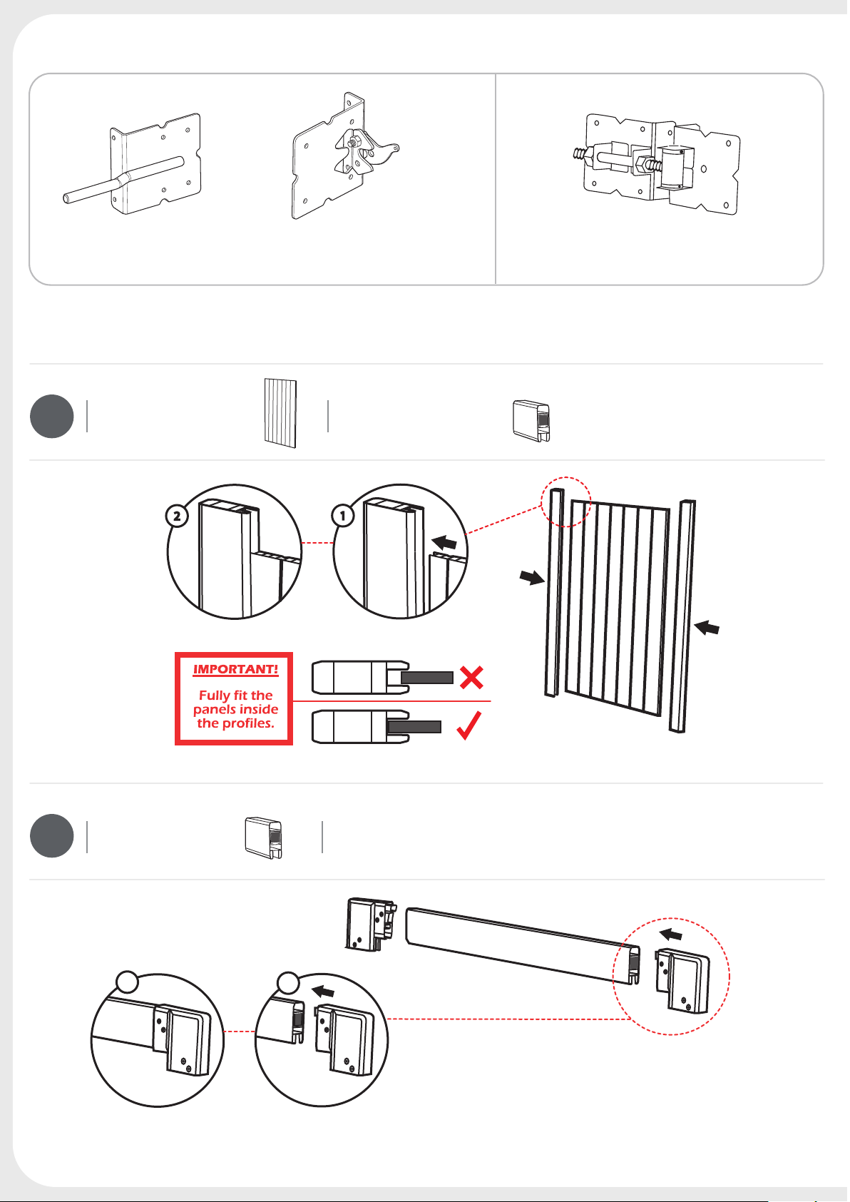
IMPORTANT
EN
You must read these instructions carefully before you start to assemble this fence. Please carry out the steps in the order set out in these instructions. Keep these instructions in a safe place for future reference. | Leer estas instrucciones con atención antes de intentar armar esta
puerta. Siga estos pasos en el orden que se indica en las instrucciones, las cuales deberá guardar en un lugar seguro, para su futura referencia. |
FR
Veuillez lire ces instructions attentivement avant de commencer à monter cette clôture. Procédez aux étapes ci-dessous dans l'ordre indiqué.
Conservez ces instructions dans un lieu sûr pour toute éventuelle consultation ultérieure. | Lesen Sie diese Anweisungen sorgfältig bevor
Sie mit der Montage des Tors beginnen. Bitte führen Sie die einzelnen Arbeitsschritte in der hier beschriebenen Reihenfolge aus. Bewahren Sie diese
Anleitung an einem sicheren Ort zum späteren Nachschlagen auf. | Leggere attentamente queste istruzioni prima di iniziare ad assemblare
il cancello. Seguire queste procedure nell’ordine indicato nelle istruzioni. Conservare queste istruzioni in un luogo sicuro per futuri riferimenti.
|
IMPORTANTE
|
IMPORTANT
|
IT
WICHTIG
ES
|
IMPORTANTE |
DE
GENERAL INFORMATION
INFORMATIONEN
EN
The Keter gate is easy to install. We incorporate methods and procedures used by professional installers to guide you through to the successful
completion of your fence. | La puerta Keter es fácil de instalar. Incorporamos métodos y procedimientos empleados por instaladores
profesionales para guiarlo mientras completa correctamente el armado de su cerca. | La clôture Keter est facile à installer. Les instructions réunissent les méthodes et procédures utilisées par des installateurs professionnels, an de vous guider et de vous aider à réussir l'installation
de votre clôture. | Das Keter Tor ist einfach zu installieren. Wir verwenden Methoden und Vorgänge, die von professionellen Handwerkern
verwendet werden, um Sie erfolgreich durch die Montage Ihres Tors zu leiten. | Il cancello Keter è semplice da installare. I metodi e le
procedure da noi adottate sono utilizzate da installatori professionisti per guidarvi attraverso la giusta installazione della vostra recinzione. |
GENERAL ADVICE
|
DE
|
SUGGERIMENTI GENERALI
EN
This is a 2 person assembly job. If it is a property line fence, you will want to conrm your property lines before ordering your fence. The component parts should be checked and laid out in an orderly way, close at hand. Keep all small parts (screws, etc.) in a bowl so that they do not get lost.
Please keep the tracking number which appears on the box, and refer to this number when calling the service oce for questions or complaints. |
Esta tarea de armado requiere la intervención de 2 personas. Si se trata de una cerca para delimitar una propiedad, le conviene conrmar cuáles
ES
son los límites de la misma antes de pedir su cerca. Las partes componentes deben ser vericadas y tendidas en forma ordenada y debe tenerlas a
mano. Mantenga todas las partes pequeñas (tornillos etc.) en un recipiente, para no perderlos. Conserve el número de guía [tracking number] que
aparece en la caja y remítase a este número cuando llame a la ocina de servicio para hacer preguntas o reclamos. | Le montage doit être
eectué par 2 personnes. S'il s'agit d'une clôture délimitant une propriété, veuillez conrmer la limite de votre propriété avant de commander votre
clôture. Vériez les composants et disposez-les de manière ordonnée tout en les gardant à portée de mains. Conservez les petites pièces (vis, etc.)
dans un bol, an de ne pas les égarer. Veuillez conserver le numéro de référence qui gure sur la boîte d'emballage et vous y référer lorsque vous
contactez notre service clientèle pour toutes questions ou réclamations. | Für die Montage werden 2 Personen benötigt. Falls es sich um
einen Zaun zur Grundstücksabgrenzung handelt, sollten Sie die Grundstücksgrenzen überprüfen, bevor Sie den Zaun bestellen. Die Bauteile sollten
überprüft und systematisch und gribereit ausgelegt werden. Geben Sie alle Kleinteile (z.B. Schrauben etc.) in eine Schüssel, so dass nichts verloren
geht. Bitte bewahren Sie die Frachtnummer, die auf dem Karton angegeben ist, auf, um diese Nummer angeben zu können, falls Sie sich für Fragen
oder Beschwerden an das Servicebüro wenden sollten. | Questo lavoro di assemblaggio va eettuato da 2 persone. Nel caso si tratti di
un cancello di delimitazione della proprietà, bisognerà confermare i conni della proprietà prima di ordinare il cancello. Controllare le parti dei componenti e sistemarle in modo ordinato, a portata di mano. Conservare le parti piccole (viti, ecc.) in un contenitore onde evitare di perderle. Conservare il
codice di spedizione indicato sulla scatola, facendo riferimento ad esso quando si contatta il servizio assistenza per domande o reclami. |
|
INFORMACIÓN GENERAL
INFORMAZIONI GENERALI
ES
CONSEJOS GENERALES
|
|
|
INFORMATIONS GÉNÉRALES
|
FR
IT
CONSIGNES GÉNÉRALES
DE
IT
|
ALLGEMEINE
|
ALLGEMEINE HINWEISE
FR
|
CARE & MAINTENANCE
INSTANDHALTUNG
EN
DO NOT use acetone, abrasive cleaners or other special detergents to clean the fence. | Use acetona, limpiadores abrasivos u otros de-
tergentes especiales para limpiar la puerta. | Pour nettoyer la clôture, utilisez une solution détergente douce et rincez à l'eau froide. NE
PAS UTILISER d'acétone, ni de nettoyants abrasifs ou d'autres détergents spéciaux pour nettoyer la clôture. | Benutzen Sie zur Reinigung
des Tors NIEMALS Azeton, aggressive Reinigungsmittel oder andere Spezialreiniger. | Per pulire il cancello, utilizzare una soluzione
detergente leggera e risciacquare con acqua fredda. NON utilizzare acetone, detergenti abrasivi o altri detergenti particolari. |
2
|
CUIDADOS Y MANTENIMIENTO
|
PULIZIA E MANUTENZIONE
FR
|
ENTRETIEN
|
PFLEGE &
|
ES
DE
IT
Page 3
REQUIRED TOOLS | HERRAMIENTAS NECESARIAS | OUTILS NECESSAIRES | BENÖTIGTE WERKZEUGE |
ATTREZZATURA OCCORRENTE |
EN
The following tools are required for fence assembly | Las siguientes herramientas son necesarias para armar el cobertizo |
FR
Pour construire votre remise, vous aurez besoin des outils suivants | Für die Montage des Gartenschuppens benötigen Sie folgende
Werkzeuge | Il montaggio richiede i seguenti utensili |
IT
ES
DE
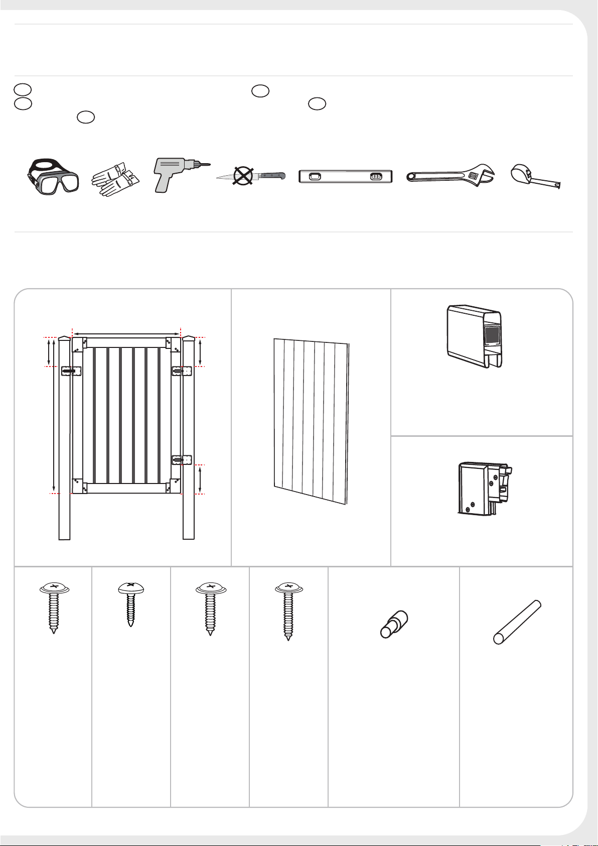
GATE DIMENSIONS & PARTS
47 1/4" (120 cm)
12 3/4"
(32 cm)
69"(175 cm)
12 3/4"
(32 cm)
12 3/4"
(32 cm)
GATE PANEL (X1)
GATE RAIL
38” (X2) 96.5
cm
66” (X2) 167.5 cm
GATE CORNER (X4)
sc35 (X12)
20mm
s15b (X16)
18
mm
s35 (X32)
20mm
sc40b (X6)
40mm
LOCKING PIN (X1)
EL PASADOR DE
BLOQUEO (X1)
GOUPILLE DE
VERROUILLAGE (X1)
SICHERUNGSSTIFT (X1)
PERNO DI BLOCCAGGIO
(X1)
LONG PIN (X1)
3
Page 4
GATE DIMENSIONS & PARTS
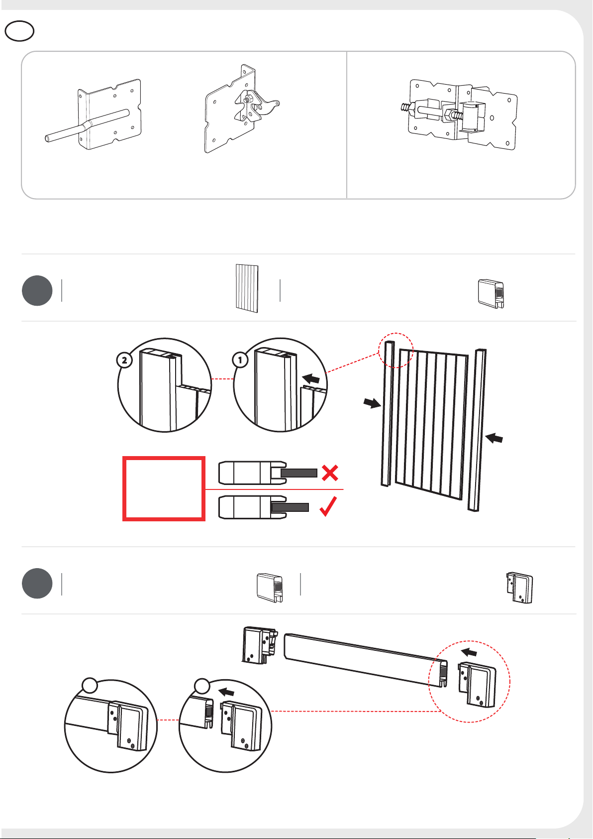
GATE ASSEMBLY
LATCH (X1) HINGE (X2)
1
GATE ASSEMBLY
GATE PANEL (X1) GATE RAIL (X1)
2
4
GATE RAIL (X1) GATE CORNER (X4)
2
1
Page 5
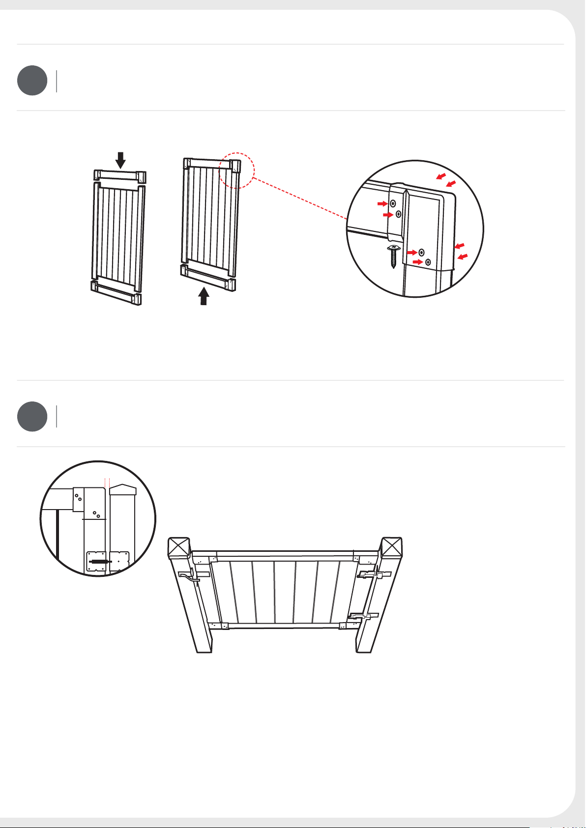
GATE ASSEMBLY
3
s35
(x32)
INSTALLING THE FENCE GATE
4
1”(2.5cm) gap
Gap between post & gate: 1" (2.5 cm)
STABLE GATE POSTS:
1. Prevent sagging of the gate and give strong support to the hinge xtures.
2. It is highly recommended to strengthen the gate post with wet / dry concrete
after assembling the gate and gate hardware.
5
Page 6
INSTALLING THE FENCE GATE
5
opening direction
12 3/4"
(32 cm)
12 3/4"
(32 cm)
WHICH SIDE SHOULD THE
HINGES GO ON?
12 3/4"
(32 cm)
sc40b
(x2)
sc35
(x4)
1. The main plate of the hinge
goes on the INSIDE of the gate.
2. Once you decide which side to
put the hinges on, mark their
positions on the gate (12 3/4" / 32
cm from the top & bottom of the
gate) and install using the
supplied screw. Each hinge
requires 4 (sc35) screws on the
front plate, and 2 (sc40b) screws
on the side plate.
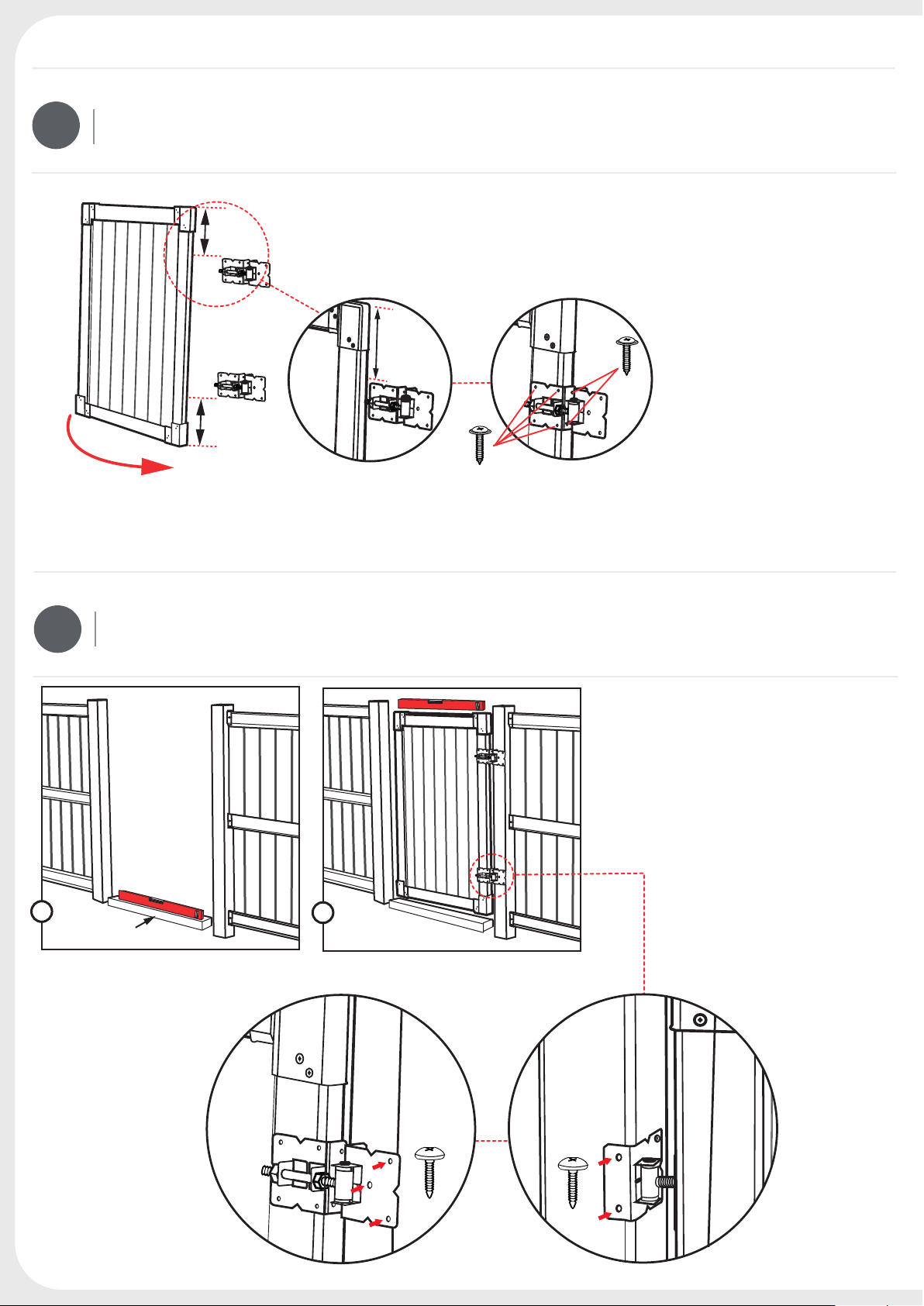
INSTALLING THE GATE HINGES
6
1
Temporary base
min. 2” (5cm) high
1. Position the assembled gate on
a temporary base (between 2”- 4” /
5-10cm high). Correct the timber
or blocks so that the gate is
horizontal and aligned with the
posts.
2. Fix the top hinge rst, followed
by the bottom hinge. Mark the
position of the hinge plate holes,
2
and attach the hinges to the post,
using screws.
X2
X2
s15b
18mm
(x3)
6
s15b
18mm
(x2)
Open the gate
& x the screw
Page 7
GATE ALIGNMENT
7
GATE RAIL (X1) GATE CORNER (X4)
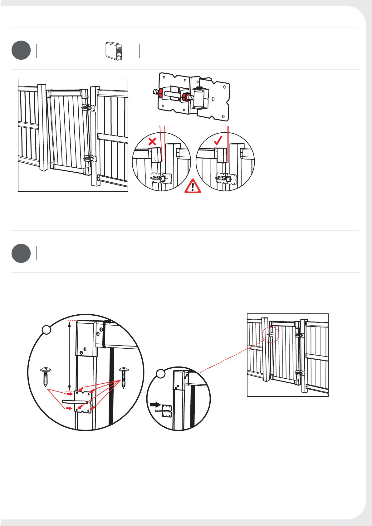
INSTALLING THE GATE LATCH
1. Remove the timber.
2. Check gate alignment with
the builder's level.
3. If correction is required, open
the nut between the hinge parts,
and move the gate.
4. Finally, tighten the nut in the
correct gate position.
8
2
sc40b
(x2)
(32 cm)
12 3/4"
sc35
(x4)
1
7
Page 8
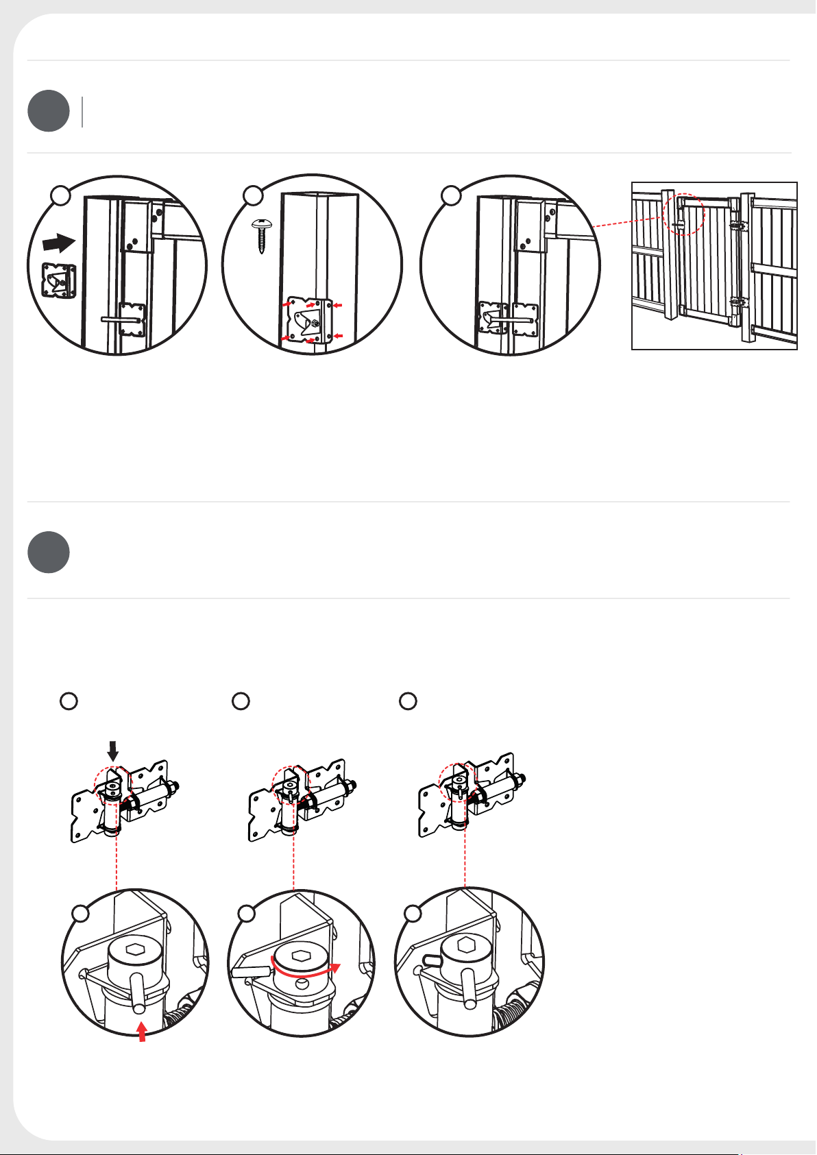
INSTALLING THE GATE LATCH
9
1 2 3
s15b
(x6)
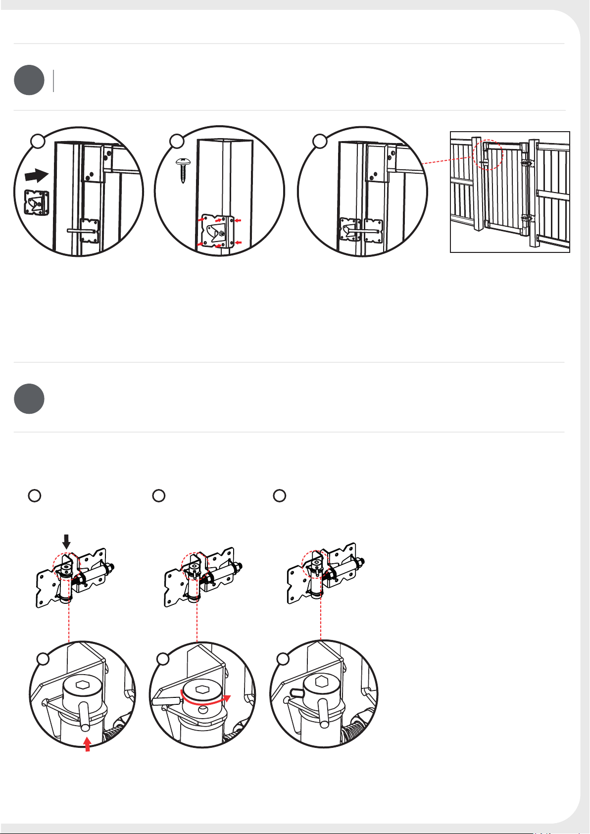
SPRING TENSION ADJUSTMENT AND MAINTENANCE
10
1 2 3
Insert supplied
long pin into
adjustment cam.
Rotate the
long pin
counter-clockwise.
Insert adjustment pin
into hole in
adjustment cam.
Carefully rotate the adjustment
cam clockwise until the
adjustment pin contacts the
fence post leaf spring.
Remove the long pin.
Repeat until gate closes rmly.
Do not adjust more than 1-1/2
turns from neutral.
1 2
3
The hinges should be inspected
annually or more frequently if the
gate is used often. Spring
tension adjustments should be
made as needed. If needed, the
spring can be lubricated with an oil
based lubricant applied to the cam
and barrel portion of the hinge.
8
Page 9
ES
DIMENSIONES Y PARTES DE LA PUERTA
ARMADO DE LA PUERTA
BISAGRA (X2)PESTILLO (X1)
1
ARMADO DE LA PUERTA
PANEL DE LA PUERTA (X1) BARANDA DE LA PUERTA (X1)
IMPORTANTE!
Calce los paneles
dentro de los
perfiles hasta el
fondo
2
BARANDA DE LA PUERTA (X1)
2
1
ESQUINERO DE LA PUERTA (X4)
9
Page 10

ARMADO DE LA PUERTA
3
s35
(x32)
INSTALACIÓN DE LA PUERTA DE LA CERCA
4
Distancia de 1”
(2.5cm)
Distancia entre el poste y la puerta de 1" (2,5 cm)
10
POSTES ESTABLES PARA LA PUERTA:
1. Para evitar pandeos de la puerta y brindar un fuerte soporte a los accesorios de las bisagras.
2. Se recomienda especialmente reforzar el poste de la puerta con cemento mojado/seco después
de terminar de armar la puerta y los accesorios de la misma.
Page 11

INSTALACIÓN DE LA PUERTA DE LA CERCA
5
12 3/4"
32 cm
DE QUÉ LADO HAY QUE
PONER LAS BISAGRAS?
12 3/4"
32 cm
Dirección de apertura
INSTALACIÓN DE LAS BISAGRAS DE LA PUERTA
6
32 cm
12 3/4"
sc35
(x4)
sc40b
(x2)
1. La placa principal de las bisagras
va hacia ADENTRO de la puerta.
2. Una vez que decida de qué
lado colocar las bisagras, marque
sus posiciones en la puerta
(12 3/4" / 32 cm desde la parte
superior y de la base de la puerta)
e instale usando el tornillo
provisto. Cada bisagra requiere 4
tornillos (sc35) en la placa
delantera y 2 tornillos (sc40b) en la
placa lateral.
1. Ubique la puerta armada en
una base temporaria (entre 2”- 4”
5-10 cm de altura).
Corrija el madero o los bloques de
manera tal que la puerta quede
horizontal y alineada con los
postes.
1
Temporary base
min. 2” (5cm) high
2. Fije la bisagra superior primero,
seguida por la bisagra de base.
2
X2
Marque la posición de los agujeros
de la placa de la bisagra y atornille
las bisagras al poste usando
tornillos.
X2
s15b
18mm
(x3)
s15b
18mm
(x2)
Abra la puerta y
je el tornillo
11
Page 12

ALINEACIÓN DE LA PUERTA
7
BARANDA DE LA PUERTA (X1)
INSTALACIÓN DEL PESTILLO DE LA PUERTA
ESQUINERO DE LA PUERTA (X4)
1.
Retire el madero.
2.
Verique la alineación de la puerta
usando el nivel.
3
Si se requiere corrección, abra la
tuerca entre las partes de la bisagra y
mueva la puerta.
4.
Finalmente, ajuste la tuerca en su
posición correcta.
8
2
sc40b
(x2)
(32 cm)
12 3/4"
sc35
(x4)
1
12
Page 13
INSTALACIÓN DEL PESTILLO DE LA PUERTA
9
1 2 3
s15b
(x6)
MANTENIMIENTO Y AJUSTE DE LA TENSIÓN DEL RESORTE
10
1 2 3
Inserte la llave
de latuerca
hexagonalprovista
en la levade ajuste.
Gire la llavede
la tuercahexagonal
en Sentido anti
horario.
Inserte el perno de
ajuste en el oricio
de la leva de ajuste.
Gire cuidadosamente la leva de
ajuste en sentido horario, hasta
que el perno de ajuste entre en
contacto con el resorte de hojas
del poste de la cerca. Retire la
llave de la tuerca hexagonal.
Repita hasta que la puerta cierre
con rmeza.
No ajuste más de 1-1/2 vueltas
desde el punto neutral.
1 2
3
Las bisagras deben inspeccionarse todos
los años o con mayor frecuencia, en caso
de que la puerta se use a menudo.
Los ajustes de tensión del resorte deben
llevarse a cabo conforme a las necesidades.
Si hace falta, el resorte se puede lubricar
con un lubricante de base aceitosa, aplicado
a la leva y a la porción del tambor de la
bisagra.
13
Page 14

DIMENSIONS DU PORTAIL ET SES COMPOSANTS
FR
LOQUET (X1) CHARNIÈRE (X2)
ASSEMBLAGE DU PORTAIL
1
ASSEMBLAGE DU PORTAIL
PANNEAU DE PORTAIL (x1) TRAVERSE DE PORTAIL
IMPORTANT !
Placez les
panneaux
entièrement à
l'intérieur des profils.
14
2
TRAVERSE DE PORTAIL (X1) ANGLE DE PORTAIL (X4)
2
1
Page 15

ASSEMBLAGE DU PORTAIL
3
s35
(x32)
INSTALLATION DU PORTAIL DE LA CLÔTURE
4
Écart 2,5 cm
Écart entre le poteau et le portail : 2,5 cm
DES POTEAUX DE PORTAIL STABLES :
1. Évitent l’aaissement du portail et apportent un support
solide au montage des charnières.
2. Il est fortement recommandé de renforcer les poteaux de
portail avec du béton sec ou mélangé après avoir terminé
l'assemblage de la clôture et de ses équipements.
15
Page 16

INSTALLATION DU PORTAIL DE LA CLÔTURE
5
32 cm
DE QUEL CÔTÉ PLACER LES
CHARNIÈRES ?
32 cm
Sens de l'ouverture
INSTALLATION DES CHARNIÈRES DE PORTAIL
6
32 cm
sc35
(x4)
sc40b
(x2)
1. La plaque principale des
charnières se place à l’INTÉRIEUR
du portail.
2. Une fois que vous avez décidé
de quel côté placer les charnières,
marquez leurs positions sur le
portail (32 cm) du sommet au bas
du portail) et
installez-les à l’aide des vis
fournies. Chaque charnière
nécessite 4 vis (sc35) sur sa plaque
avant et 2 vis (sc40b) sur sa plaque
latérale.
1. Positionnez le portail assemblé
sur une base temporaire (5-10 cm)
de haut maximum.
Corrigez le piquet ou les blocs an
que le portail soit horizontal et
aligné avec les poteaux.
1
Base temporaire
(5 cm de haut minimum)
16
2. Positionnez le portail assemblé
sur une base temporaire (5-10 cm)
de haut maximum.
2
X2
Corrigez le piquet ou les blocs an
que le portail soit horizontal et
aligné avec les poteaux.
X2
s15b
18mm
(x3)
s15b
18mm
(x2)
Ouvrez le portail
et xez la vis.
Page 17

ALIGNEMENT DU PORTAIL
7
TRAVERSE DE PORTAIL (X1) ANGLE DE PORTAIL (X4)
INSTALLATION DU LOQUET
1. Retirez le piquet.
2. Vériez l’alignement du portail
avec le niveau.
3. Si une correction est nécessaire,
desserrez l’écrou entre les pièces
de la charnière et déplacez le
portail.
4. Enn, serrez l’écrou une fois le
portail en position correcte.
8
2
sc40b
(x2)
32 cm
sc35
(x4)
1
17
Page 18

INSTALLATION DU LOQUET
9
1 2 3
s15b
(x6)
RÉGLAGE ET ENTRETIEN DE LA TENSION DU RESSORT
10
Insérez la clé
1 2 3
hexagonale fournie
dans la came de
réglage.
Tournez la clé dans
le sens contraire
des aiguilles d’une
montre.
Insérez la goupille
de réglage dans
l’orice de la came
de réglage.
Tournez délicatement la came
de réglage dans le sens des
aiguilles d’une montre jusqu’à
ce que la goupille de réglage entre en
contact avec le volet du poteau de la
clôture. Retirez la clé hexagonale.
Répétez l’opération jusqu’à ce que le
portail se ferme solidement.
Ne faites pas plus d’un tour et demi
au-delà du point initial.
18
31 2
Les charnières doivent être inspectées
chaque année ou plus fréquemment si
le portail est souvent utilisé. Les réglages
de la tension du ressort doivent être
réalisés chaque fois que cela est nécessaire.
Si besoin est, le ressort peut être graissé
avec un lubriant à base d’huile,
à appliquer sur la came et sur la partie du
barillet de la charnière.
Page 19

DE
ABMESSUNGEN & TEILE DES TORS
TORMONTAGE
SCHARNIER (X2)RIEGEL (X1)
1
TORMONTAGE
TORPLATTE (X1) TORLEISTE (X1)
WICHTIG:
Fügen Sie die
Platten vollständig
in die Prole ein.
2
TORLEISTE (X1)
2
TORECKSTÜCK (X4)
1
19
Page 20

TORMONTAGE
3
s35
(x32)
MONTAGE DES ZAUNTORS
4
ABSTAND 2,5cm
Abstand zwischen Pfosten & Tor 2,5cm
20
STABILE TORPFOSTEN:
1. Vermeiden Sie ein Absinken des Tors und stellen Sie den starken
Halt der Scharnierbefestigungen sicher.
2. Es wird wärmstens empfohlen, den Torpfosten nach dem
Zusammenbau des Tors und dessen Zubehör mit Nass-/ Trockenbeton zu verankern.
Page 21

MONTAGE DES ZAUNTORS
5
32 cm
AN WELCHER SEITE SOLLEN DIE
SCHARNIERE ANGEBRACHT
WERDEN?
32 cm
Önungsrichtung
MONTAGE DER SCHARNIERE
6
32 cm
sc40b
(x2)
sc35
(x4)
1. Die Hauptplatte der Scharniere
wird an der INNENSEITE
des Tors angebracht.
2. Nachdem Sie entschieden
haben, an welcher Seite Sie die
Scharniere anbringen, markieren
Sie die entsprechenden Positionen
am Tor (32cm von der Spitze und
vom Boden des Tors entfernt) und
montieren Sie diese mit der
mitgelieferten Schraube. Für jedes
Scharnier werden 4 Schrauben
(sc35) auf der Vorderplatte und 2
Schrauben (sc40b) an der Seitenplatte benötigt.
1. Positionieren Sie das vormontierte Tor auf einer provisorischen
Basis (zwischen 5-10cm hoch).
Korrigieren Sie die Lage der
Holzklötze oder Blöcke so, dass das
Tor horizontal und auf die Pfosten
ausgerichtet ist.
1
Provisorische
Basis mind. 5cm hoch
2. Bringen Sie zuerst das obere
und dann das untere Scharnier an.
2
X2
Markieren Sie die Positionen der
Scharnierplattenlöcher und
bringen Sie die Scharniere mit
Schrauben am Pfosten an.
X2
s15b
18mm
(x3)
s15b
18mm
(x2)
Önen Sie das Tor
und montieren Sie
die Schrauben.
21
Page 22

AUSRICHTEN DES TORS
7
TORLEISTE (X1)
MONTAGE DER TORRIEGELS
TORECKSTÜCK (X4)
1.
Entfernen Sie die Holzklötze.
2.
Überprüfen Sie die Ausrichtung
des Tors mit Hilfe der Wasserwaage.
3.
Falls etwas verändert werden
muss, lockern Sie die Mutter
zwischen den Scharnierteilen und
bewegen Sie das Tor.
4.
Ziehen Sie die Mutter in der
korrekten Torposition fest.
8
2
sc40b
(x2)
32 cm
sc35
(x4)
1
22
Page 23

MONTAGE DER TORRIEGELS
9
1 2 3
s15b
(x6)
EINSTELLUNG DER FEDERSPANNUNG UND WARTUNG
10
21 3
Stecken Sie den
mitgelieferten langen
Pin in die Einstellnocke
Drehen Sie den
langen Pin gegen
den Uhrzeigersinn.
Stecken Sie den
Einstellstift in das
Loch in der
Einstellnocke.
Drehen Sie die Einstellnocke
vorsichtig im Uhrzeigersinn,
bis der Einstellstift die Blattfeder
des Zaunpfostens berührt.
Wiederholen Sie den Vorgang,
bis das Tor fest schließt.
Nehmen Sie keine Änderungen vor,
die mehr als 1 1/2 Umdrehungen von
der Nullstellung abweichen.
31 2
Die Scharniere sollten jährlich oder, falls
das Tor sehr häug benutzt wird, auch öfter
gewartet werden.
Die Federspannung sollte, falls notwendig,
angepasst werden. Falls notwendig, kann
die Feder mit einem Schmiermittel auf
Öl-Basis geschmiert werden. Dieses sollte
auf den Einstellnocken und das Gehäuse
des Scharniers gegeben werden.
23
Page 24

DIMENSIONI DEL CANCELLO E PARTI
IT
MONTAGGIO CANCELLO
CHIAVISTELLO (X1) CERNIERA (X2)
1
MONTAGGIO CANCELLO
PANNELLO CANCELLO (x1) TRAVERSA CANCELLO
IMPORTANTE!
Inserire i pannelli
no in fondo
all’interno dei proli.
24
2
TRAVERSA CANCELLO (X1) PARTE ANGOLARE DEL CANCELLO (X4)
2
1
Page 25

MONTAGGIO CANCELLO
3
s35
(x32)
INSTALLAZIONE DEL CANCELLO DI RECINZIONE
4
Intercapedine
2,5cm
Intercapedine tra palo e cancello 2,5cm
FISSARE I PALI IN MODO STABILE:
1. Fare in modo che il cancello non si curvi nella parte centrale
e sostenere bene i supporti di ssaggio delle cerniere.
2. Dopo aver montato il cancello e le sue parti metalliche si
consiglia vivamente di rinforzare il palo del cancello con
calcestruzzo umido / secco.
25
Page 26

INSTALLAZIONE DEL CANCELLO DI RECINZIONE
5
32 cm
SU QUALE LATO VANNO
POSIZIONATE LE CERNIERE?
32 cm
direzione di apertura
MONTAGGIO DELLE CERNIERE
6
32 cm
sc40b
(x2)
sc35
(x4)
1. La piastra principale della
cerniera deve trovarsi NELLA
PARTE INTERNA del cancello.
2. Una volta deciso il lato su cui
posizionare le cerniere,
contrassegnarne le posizioni sul
cancello a 32 cm dalla parte
superiore e inferiore) e montarle
utilizzando la vite in dotazione.
Ogni cerniera necessita di 4 viti
(sc35) sulla piastra anteriore, e 2
viti (sc40b) su quella laterale.
1. Posizionare il cancello montato
su una base provvisoria
(tra 5-10 cm di altezza).
Ripassare con la trave di legno
squadrato o i blocchi in modo tale
che il cancello sia in orizzontale e
allineato ai pali.
1
26
Base provvisoria
min. 5cm di altezza
2. Fissare prima la cerniera superiore, poi quella inferiore.
2
X2
Contrassegnare la posizione dei
fori della piastra, e ssare le
cerniere al palo, utilizzando le viti.
X2
s15b
18mm
(x3)
s15b
18mm
(x2)
Aprire il cancello
e ssare la vite.
Page 27

ALLINEAMENTO DEL CANCELLO
7
TRAVERSA CANCELLO (X1) PARTE ANGOLARE DEL CANCELLO (X4)
MONTAGGIO DELLA CHIUSURA A SCATTO
1. Rimuovere la trave di legno
squadrato.
2. Vericare l’allineamento del
cancello con il livello indicato dal
costruttore.
3. Nel caso sia necessaria una
correzione, aprire il dado posto tra
le cerniere, e spostare il cancello.
4. Inne, stringere il dado nella
posizione corretta.
8
2
sc40b
(x2)
32 cm
sc35
(x4)
1
27
Page 28

MONTAGGIO DELLA CHIUSURA A SCATTO
9
1 2 3
s15b
(x6)
REGOLAZIONE E MANUTENZIONE DELLA TENSIONE DELLA MOLLA
10
21 3
Inserire la chiave a
brugola in dotazione
all’interno della camma
di regolazione.
Ruotare la chiave
a brugola in senso
antiorario.
Inserire il perno di
regolazione nel foro
all’interno della camma.
Ruotare attentamente la camma di
regolazione in senso orario no a
quando il perno di regolazione non
tocca la molla a balestra del palo.
Rimuovere la chiave a brugola.
Ripetere l’operazione no a
quando il cancello non si chiude
stabilmente. Non regolare per più
di 1-1/2 giri dalla posizione neutra.
28
31 2
Ispezionare le cerniere ogni anno o con
maggiore frequenza qualora il cancello
venga utilizzato spesso.
Le regolazioni della tensione delle molle
vanno eettuate all’occorrenza. In caso di
necessità, lubricare le molle applicando
del lubricante a base di olio sulla camma
e sulla parte cilindrica della cerniera.
 Loading...