

Page 1
Sauter GmbH
Ziegelei 1
TF / TG
D-72336 Balingen
E-Mail: info@sauter.eu
Instruction Manual
DIGITAL COATING THICKNESS GAUGE
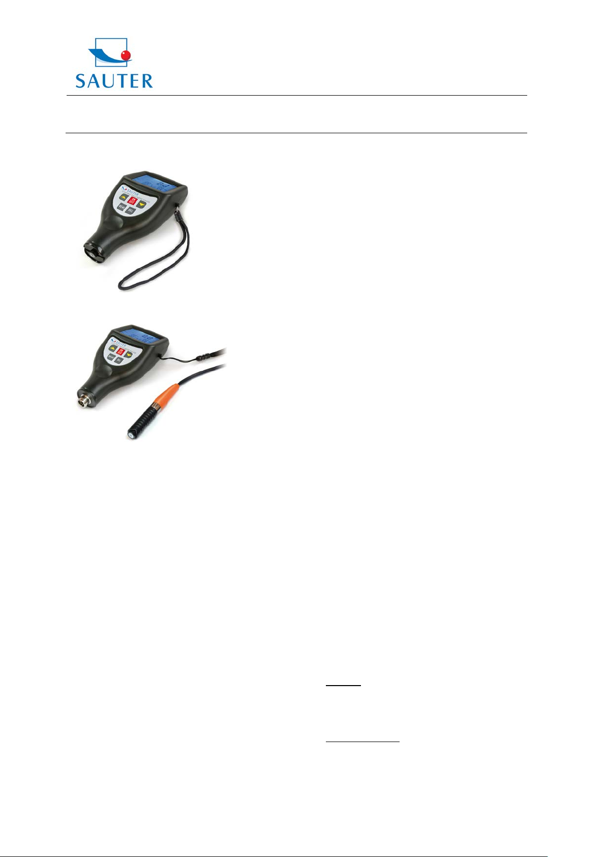
Model: TF, F and NF, with sensor inside
Model: TG, F and NF, with sensor outside
Table of contents
1. Features
2. Specifications
3. Front panel description
4. Measuring procedure
5. Statistics
6. How to store and recall readings
7. How to delete readings
8. Transfer of readings to a PC
9. Calibration
10. Battery replacement
11. Correct handling of coating thickness
measurement with external sensors
12. Trouble shooting
13. Restaure factory settings
14. Notes
15. Declaration of conformity
Annotation: It is strongly recommended to calibrate
the new instrument before the first use, as
described in paragraph 9. By doing this it
will be achieved a much better measure ment result right from the start.
1. Features
* This instrument meets the standards of both, ISO 2178
and ISO 2361, and DIN as well as ASTM und BS.
Tel: +49-[0]7433- 9933-199
Fax: +49-[0]7433-9933-149
Internet: www.kern-sohn.com
It is suitable for the laboratory and for use in
`harsh field conditions.`
* The F mode measures the thickness of nonmagnetic
materials, e.g. paint, plastic, porcelain enamel, copper,
zinc, aluminium, chrome, laquer layers etc. These layers
are located on magnetic materials e.g. steel, iron,
nickle etc. It is often used to measure the thickness of
galvanizing layer, laquer layer, porcelain enamel layer,
phosphide layer, copper tile, aluminium tile, some alloy
tile, paper etc. Those layers are to be found on magnetic
base materials like iron, steel, nickel et c.
* The N mode measures the thickness of nonmagnetic
coatings, e.g. anodizing, varnish, paint, enamel, plastic
coatings, powder etc. These layers are located on non magnetic metals e.g. aluminium, brass, non magnetic
stainless steel etc.
* Automatically substrate recognition
* Manually or automatically “auto power off” to conserve
batteries.
* Two measurement modes: - single and continuous
* Wide measuring range and high resolution
* Metric/ imperial conversion
* Digital backlight display enables exact reading with no
guessing or errors
* Can communicate with PC for statistics and printing by
the optional cable.
* Can store up to 99 measurements
* Statistics available
1. Specifications
Display: 4 digits LCD, with backlight
Range: 0 up to 1250 µm/ 0 up to 50 mil
(another range may be specified)
Resolution: 0.1µm (0 up to 99.9µm)
1µm (over 100µm)
Accuracy:
-
Standard: 3% of the measured value or min. ± 2.5 µm
Is valid within a toleranc e range of ± 100 μm around the
individually measured range, if a two-point calibrat ion was
performed within this tolerance range.
-
Off-Set Accur Mode: 1% of the measured value
or min. ± 1.0 µm
Is valid within ± 50 μm around the Off-Set Accur point.
PC interface: mit RS-232C interface
TF_TG-BA-e-1311 1
Page 2
Sauter GmbH
Ziegelei 1
TF / TG
D-72336 Balingen
E-Mail: info@sauter.eu
Instruction Manual
Power supply: 2 x 1.5V AAA(UM-4) batteri es
Operating conditions
Temperatures 0 up to 50°C
Humidity < 95 %
Dimensions: 126 x 65 x 35 mm (5.0 x 2.6 x 1.6 inch)
Weight: ca.81g (without batteries)
Accessories: - Carrying case
- Operation manual
- F-s ensor, (inbuilt at TF, at TG one sensor
for F and FN is extern, it has to be
plugged in)
- NF-sensor, (inbuilt at TF)
- Calibration foils
- Base plate (iron)
- Base plate (aluminium)
Optional accessories: Cable & software for RS-232C
USB adapter for RS-232C Software
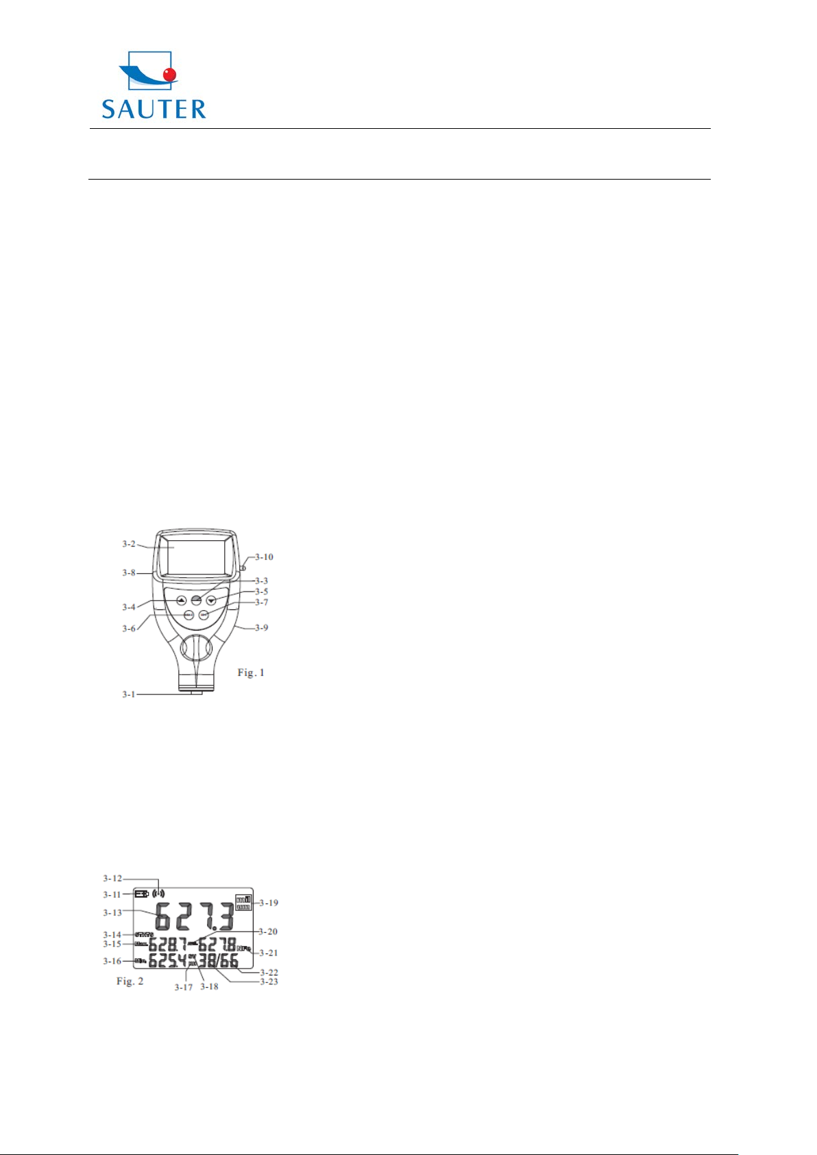
3. Front panel description
3- 1 Sensor, inbuilt at model TF
3- 2 Display
3- 3 Power-key/Zero- key
3- 4 Plus - key
3- 5 Minus- key
3- 6 Reading key
3- 7 Deleting key
3- 8 Jack for RS-232C interface
3- 9 Battery cover
3-10 Wrist ring
3-11 Low battery indicator
3-12 Measuring symbol
3-13 Last reading/browsing value
3-14 Single measurement mode
3-15 Max. indicator value
Tel: +49-[0]7433- 9933-199
Fax: +49-[0]7433-9933-149
Internet: www.kern-sohn.com
3-16 Min. indicator value
3-17 Browsing state
3-18 Measuring state
3-19 Unit
3-20 Average indicator
3-21 Substrate indicator
3-22 Counter for storing
3-23 Counter for statistics
4. Measuring procedure
At model TG, the F-/NF- sensor (aut omat ically recogniti on)
has to be plugged in, to get into the F- or NF- mode.
4.1 The power key 3-3 has to be pressed to switch on the
instrument. `0` appears on the display 3-2.
With the Auto- Mode, the instrument recognizes the
mode itself by the symbol `Fe` (= F) or `NFe`(= N)
which is indicated on the display.
4.2 The sensor 3-1 is to be placed onto a coating layer to
be measured. The reading on the display is the thick ness of the coating layer. This can be corrected by
pressing the Plus- key 3-4 or the Minus- key 3-5
For doing this the sensor should be away from the
measured object or the base plate.
4.3 For the next measurement the sensor 3-1 has to be
lifted for more than 1cm and step 4.2 is to be repeated.
The instrument memorizes the continuous measured
value automatically with statistic measurement times.
Meanwhile, the Max, Min and average value will be
displayed.
4.4 To change the measurement unit from „µm“ to “mil” or
vice verse, the Power-key just has to be pressed and
not released until “UNIT” is shown on the display.
Then the same key 3-3 (this time Zero-key) has to be
pressed.
4.5 To change the measuring mode from `single` to
`continuous` or vice verse, the Power-key 3-3 has to
be pressed and not released until `SC` appears on
the display. Then the Zero- key 3-3 has to be pressed.
The symbol “STATS” represents the continuous
mode and `S` represents the single mode.
5. Statistics
This instrument calculates and displays a statistical
analysis of readings while the measurements are taken.
The statistics available are:
• Last value
• Mean value
• Highest reading marked by Max
• Lowest reading marked by Min
• Number of readings taken
To clear the statistical data before starting a new set of
data, the Zero-key just has to be pressed and releas ed. In
measurement mode, which is marked by SV , the last value
can be deleted by pressing the DEL-key. Restatistics is
calculated and displayed itself.
TF_TG-BA-e-1311 2
Page 3
Sauter GmbH
Ziegelei 1
TF / TG
D-72336 Balingen
E-Mail: info@sauter.eu
Tel: +49-[0]7433- 9933-199
Fax: +49-[0]7433-9933-149
Internet: www.kern-sohn.com
Instruction Manual
6. How to store and recall readings
6.1 The measurements taken are automatically saved in
the memory of the instrument. The m em ori zed dat a can be
browsed by pressing and releasing the READ-key to enter
into the browsing state, marked by “READ” on the display.
6.2 In browsing state, all the readi ngs memorized can be
recalled on the display by pressing the Plus-key 3-4 or the
Minus-key 3-5.
6.3 To delete only one memorized value in t he memory,
the reading to be deleted just has to be located on the
display by the Plus-key or the Minus-key. Then the DELkey has to be pressed and released. If there appears
“Err0” on the display, it is indicat ed that there i s no reading
to delete any more.
6.4 The Zero-key 3-3 has to be pressed to quit the
measurement state.
7. How to delete readings
7.1 To delete a reading on the display, the DEL-ke y has
to be pressed, no matter wheter you are located in
the measurement state marked “SV” or in browsing
state marked “RD”. Browsing state can be entered by
pressing the READ-key and measurement state is
entered by pressing the Zero-key.
7.2 To delete all readings in the memory, the DEL-key
has to be pressed in measurement state marked by
“SV” on the display for about 4 seconds until the
number of readings memorized becomes 0.
8. Transfer of readings to a PC
8.1 RS-232 software has to be installed on the PC.
During the installing process the “continue”-button
always has to be clicked.
8.2 The instrument has to be connected to the PC using
the optional cable.
8.3 The Thickness Gauge has to be switched on to
ensure that the reading screen is displayed.
8.4 The software has to be started and the instructions
included with the software Demo. EXE. have to be
followed.
9. Calibration
9.1 Zero adjustment:
Zero adjustment for `F` and `NF` should be carried
out separately. The iron base plate is to be used if
`F` is shown on the display. The base plate of
aluminium is to be used if `NF` is shown on the display.
The sensor 3-1 is to be placed carefully onto the base
plate and the Zero- key is to be pressed without lifting
the sensor. `0` appears on the display.
Attention: The calibratio n is invalid if the sensor is
not directly placed onto the base plate or another
uncoated material.
9.2 An appropriate calibration foil is to be selected accor ding to the measurement range.
9.3 The selected standard foil has to be placed onto the
base plate or the uncoated material.
9.4 The sensor 3-1 is to be pressed carefully onto the
calibration foil and then lifted.
The reading on the display is the value measured.
This can be corrected by pressing the Plus- key 3-4
or the Minus- key 3-5 while the sensor is removed
from the base plate or the measured object.
9.5 Repeat step 9.4 until the accuracy is achieved.
10. Battery replacement
10.1 If the battery symbol ``+/-`` appears on the display,
the batteries should be replaced.
10.2 The battery cover 3-9 has to be removed and the
batteries are to be taken off.
10.3 The batteries (2x1.5V AAA/UM-4) are to be inst al l ed
correctly into the case.
10.4 If the instrument is not to be used for an extended
period, batteries are to be extracted.
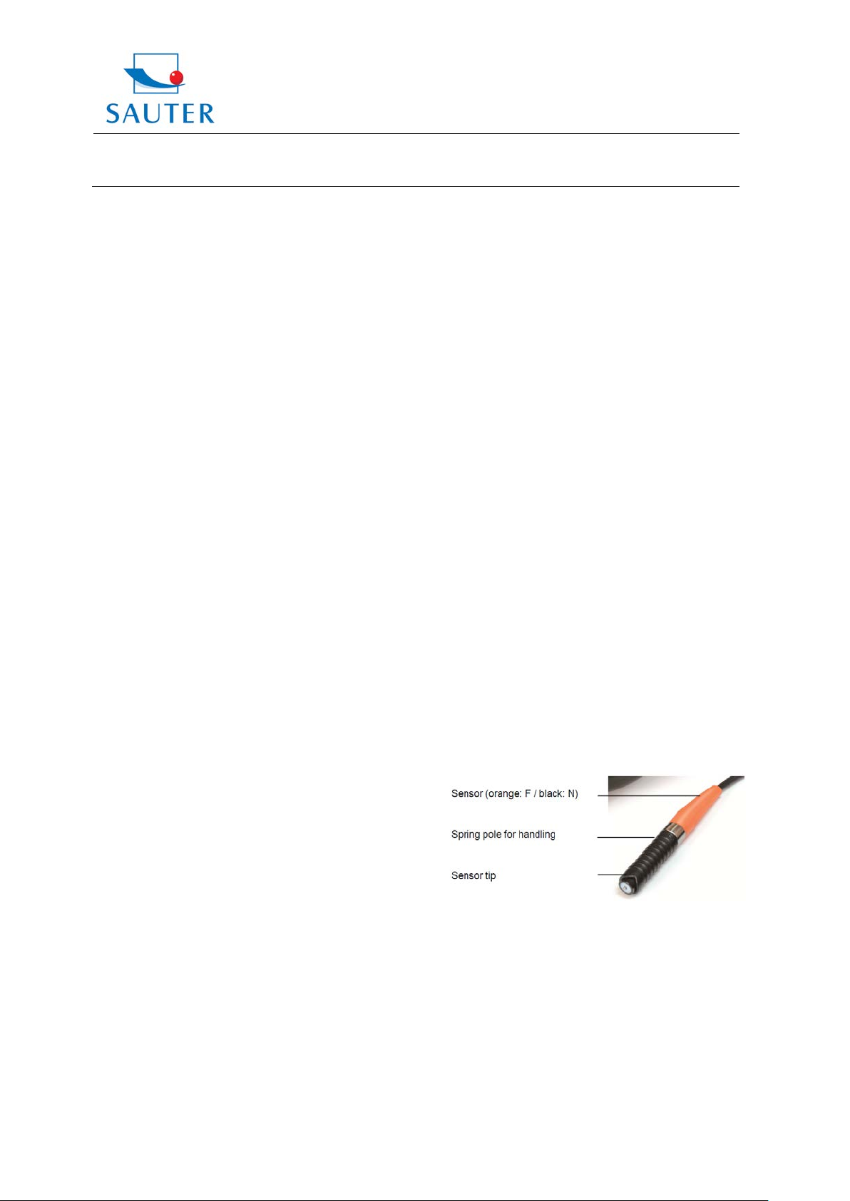
11. Correct handling of coating thickness
measurement with external sensors
The sensor has to be touched at the lower pole s egment
and it has to be pressed slightly onto the test object.
The black chequered pole segment is movably seated on a
spring. By means of the spring, the sensor tip presses onto
the test object with a defined force. This way,
measurement errors can be avoided.
It is recommendable to effect several test measurements
before the first use of the instrument. This way, further
measurement errors can be avoided.
12. Trouble shooting
12.1 The instrument should always be calibrated on the
uncoated base material to be measured instead of the
base plate included in the delivery. Then the
accuracy is more precise.
12.2 Sensors will eventually wear off. Life of the sensor will
TF_TG-BA-e-1311 3
Page 4
Sauter GmbH
Ziegelei 1
TF / TG
D-72336 Balingen
E-Mail: info@sauter.eu
Instruction Manual
depend on the number of measurements taken and
how abrasive the coating is. Replacement of the sen sor should only be performed by qualified staff.
13. Restore factory settings
13.1 In the following cases it is recommended to restore
factory settings:
A. The instrument does not measure any more.
B. Measurement accuracy is degraded caused by the
abraded sensor or affected by environmental
conditions.
C. After the replacement of a new sensor.
13.2 How to restore?
`F` setting and `N` setting are to be done. It can be
done one or both of them. The procedure is as follows:
13.2.1 On the display the symbol `F` or `NF` appears.
If `F` is shown on the display, you have to restore factory
settings for `F`, as described below.
If `NF` appears, you have to follow factory settings for
`NF`.
13.2.2 The Power-on/ Power-off key 3-3 has to be pressed
until `CAL` appears on the display. This lasts about 12
seconds from starting pressing the Power-key.
13.2.3 If now F:H or NF:H is shown on the display, the
sensor has to be lifted for m ore than 5 cm. Then the Zerokey has to be pressed and the instrument returns into
measurement mode. With this, factory setting is restored.
Comment: This procedure should always be done withi n 6
seconds. Otherwise it will be automatically cancelled and
the restoration is invalid.
14. Notes
14.1 All settings, including restoring factory setting, unit
setting, S/C setting should be done within 6 seconds.
Otherwise the instrument will quit and k eep the status as
before.
14.2 The linearization of the instrument, which is given by
the calibration, can be changed with the Ln- function.
Any adjustment of the value of Ln will seriously affect
the accuracy. This value should onl y be adjusted by
professional persons.
Generally said:
The bigger the value of Ln, the smaller the reading on
the display for the same (coating) thickness. Only a small
change on the value of Ln causes a big change in the
reading of the upper measurement range
(at 500µm/20 mil).
The value of Ln is to adjust as follows:
Tel: +49-[0]7433- 9933-199
Fax: +49-[0]7433-9933-149
Internet: www.kern-sohn.com
Pressing the Power-key. It lasts about 14 seconds from
starting depressing this key. This value can be changed by
pressing the Plus- / Minus- key after `Ln` appears on the
display and the Power- key is released. This value is
stored and afterwards the Zero- key has to be pressed.
A. The reading at low end is to be adjusted by pressing
the Plus-/ or the Minus- key.
B. The value of Ln is enlarged if reading at low end
(e.g. 51µ m) is o.k., but reading at high end (e.g.
432µm) is too large.
In contrast with this the value of Ln is to be decreased
if the reading at low end (e.g. 51µm) is o.k. but at high
end (e.g. 432µm) it is too small.
C. Procedures from A to B are to be repeated until the
reading for every calibration foil is satisfactory in
its accuracy
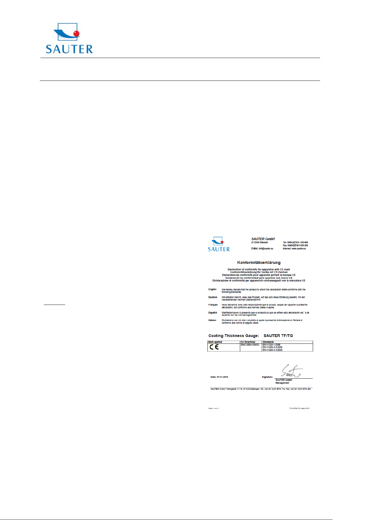
15. Declaration of conformity
TF_TG-BA-e-1311 4
 Loading...