

Page 1
Sauter GmbH
Tieringerstr. 11-15 Tel: +49-[0]7433- 9976-174
D-72336 Balingen
E-Mail: info@sauter.eu
Instruction Manual
TC_car
DIGITAL COATING THICKNESS GAUGE
Model: TC 1250-0.1 FN- car
Table of contents
1. Features
2. Specifications
3. Front panel descriptions
4. Measuring procedure
5. Calibration
6. Battery replacement
7. Calibration foils
8. Trouble shooting
9. Declaration of conformity
Annotation: It is strongly recommended to calibrate
the new instrument before the first use, as
described in paragraph 5. By doing this it
will be achieved a much better measure ment result right from the start.
1. Features
»This instrument meets the standards of both ISO 2178,
ISO 2360 as well as DIN, ASTM and BS. It is suitable for
the laboratory and for use in “harsh field” conditions.
»The F- mode measures the thickness of nonmagnetic
materials, e.g. paint, plastic, porcelain enamel, copper,
zinc, aluminium, chrome, laquer layers etc. These layers
are located on magnetic materials e.g. steel, iron,
nickle etc. It is often used to measure the thickness of
galvanizing layer, laquer layer, porcelain enamel layer,
phosphide layer, copper tile, aluminium tile, some alloy
tile, paper etc.
»The N- mode measures the thickness of nonmagnetic
coatings on nonmagnetic materials.
It is used on anodizing, varnish, paint, enamel, plastic
coatings, powder etc. It can be applied on aluminium,
brass, nonmagnetic stainless steel etc.
»Automatic substrate recognition.
»Manual or automatically auto power off to conserve
batteries
»Two measurement modes:- single and continuous
»Date transfer to PC possible
2. Specifications
Display: 4 digits
Range: 0 to 1250 µm/ 0 to 50 mil
Resolution: 0.1µm (0 to 100 µm)
1 µm (over 100 µm)
Accuracy:
Standard:
Is valid within a tolerance range of ± 100 μm around the
individually measured range, if a two-point calibration was
performed within this tolerance range.
- Off-Set Accur Mode:
or min. ± 1.0 µm
Is valid within ± 50 μm around the Off-Set Accur point.
PC- interface: with RS-232C interface
Power supply: 4x 1.5V AAA (UM-4) battery
Operating conditions:
Temperature: 0 to 50°C
Humidity: <80%
Size: 126 x 65 x 27mm (5.0 x 2.6 x 1.1 inch)
Weight: about 81g (not including batteries)
Accessories: Carrying case
Operation manual
F-sensor (inbuilt)
FN-sensor (inbuilt)
Calibration foils
Base plate (iron)
Base plate (aluminium)
Optional accessories: Cable & software for RS-232C
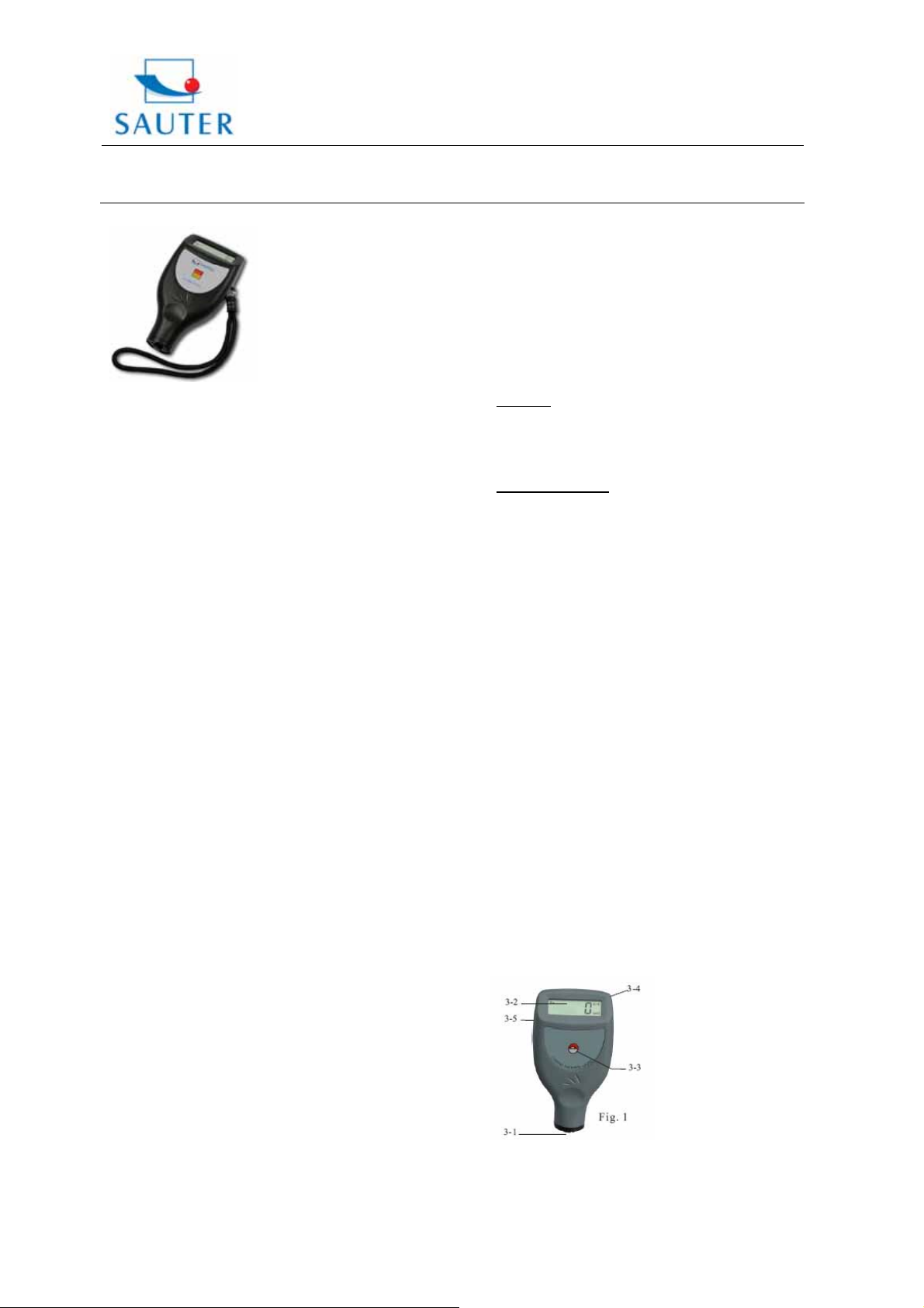
3. Front panel description
3-1 Sensors (inbuilt)
3-2 Display
3-3 Zero- key, Power- on/ Power- off key
3% of the measured value or min. ± 2.5 µm
Fax: +49-[0]7433-9976-285
Internet: www. sauter.eu
1% of the measured value
TC_car-BA-e-1110 1
Page 2
Sauter GmbH
Tieringerstr. 11-15 Tel: +49-[0]7433- 9976-174
D-72336 Balingen
E-Mail: info@sauter.eu
Instruction Manual
TC_car
3-4 Battery compartment/ cover
3-5 Jack for RS-232C interface
4. Measuring procedure
4.1 The Power- on/Power-off key 3-3 is to be pressed to
switch on the instrument.`0`appears on the display 3-2.
The instrument recognizes the sensor itself,by the
symbol `Fe` (= F) or `NFe` (= N) which is indicated
on the display. The instrument enters the auto mode
which can automatically recognize the base plate.
4.2 The sensor 3-1 is to be placed onto a coating layer to
be measured. The reading on the display is the thick ness of the coating layer.
4.3 For the next measurement the sensor 3-1 is to be
lifted for more than 1cm and step 4.2 is to be
repeated.
4.4 In case of inaccuracies to the measurement result it is
recommended to calibrate the instrument before
measuring as described in part 5.
4.5 The instrument can be switched off by pressing the
Power- on/ Power- off key 3-3. The power will switch
itself off 50 seconds after the last operation.
4.6 The measurement unit can be indicated with `µm` or
`mil`. To convert:
The Zero/ Power- on/ off key 3-3 has to be pressed
and not to be released until `UNIT` appears on the
display. The measurement unit changes by releasing.
All in all this operation lasts about 6 seconds (from
starting pressing the Zero-/ Power-on/ off key).
4.7 To change the measuring mode from `single` to `con tinuous or vice visa, the Zero/ Power- key 3-3
is to be pressed and not released until `SC` appears
on the display. The measuring mode changes into
the other one when the key is released. This lasts
about 8 seconds. The symbol ((•)) on the display
indicates the continuous mode.
5. Calibration
5.1 Zero adjustment:
Zero adjustment for `Fe` (=F) and `NFe` (=NF) should
be carried out separately.
The iron base plate is to be used if `Fe` is
shown on the display. The base plate of aluminium is
to be used if `NFe` is shown on the display.
The sensor 3-1 is to be placed carefully onto the base
plate and the Zero-/ Power key is to be pressed without
lifting the sensor. `0` appears on the display.
Attention: The calibration is invalid if the sensor is
not directly placed on the base plate or another un coated material.
6. Battery replacement
6.1 If the battery symbol ``+/-`` appears on the display, the
batteries should be replaced.
6.2 The battery cover 3-4 is to be removed and the
batteries are to be taken off.
6.3 The batteries (4x1.5V AAA/UM-4) are to be installed
Fax: +49-[0]7433-9976-285
Internet: www. sauter.eu
correctly into the case.
6.4 If the instrument is not to be used for an extended
period, batteries are to be extracted.
7. Calibration foils
As accessory there is included a foil set of different foils
and ranges, which is to be seen below.
Range
(µm)
0-200 X X X X
0-500 X X X X
01000
02000
8. Trouble shooting
8.1 The instrument should always be calibrated on the
uncoated base material to be measured instead of the
base plate included in the delivery. Then the
accuracy is more precise.
8.2 Sensors will eventually wear off. Life of the sensor will
depend on the number of measurements taken and
how abrasive the coating is.
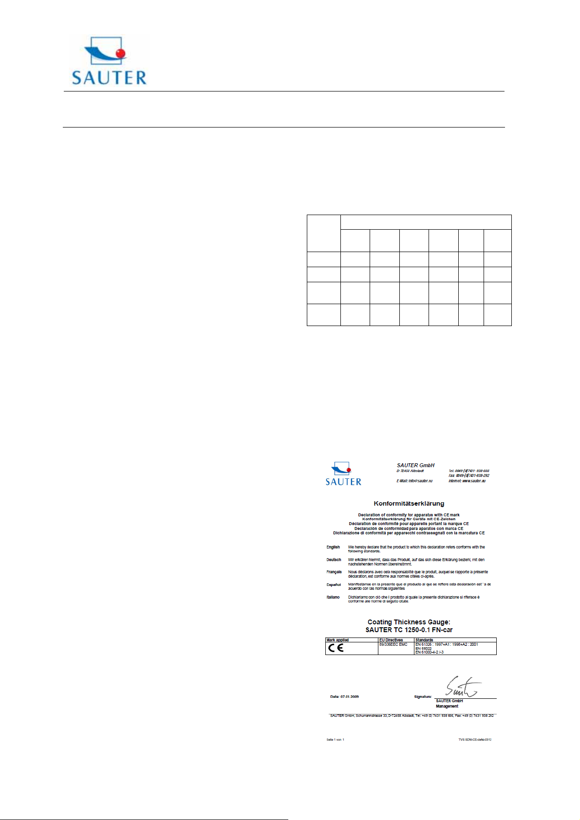
9. Declaration of conformity
STANDARD FOIL INCLUDED
CM
CM
25
50
X X X X X
X X X X X
CM
100
CM
200
CM
500
CM
1000
TC_car-BA-e-1110 2
Page 3

Sauter GmbH
Tieringerstr. 11-15
D-72336 Balingen
E-Mail: info@sauter.eu
Tel: +49-[0]7433- 9976-174
Fax: +49-[0]7433-9976-285
Internet: www. sauter.eu
Instruction Manual
TC_car
TC_car-BA-e-1110 3
 Loading...