

Page 1
Sauter GmbH
Ziegelei 1
TB
D-72336 Balingen
E-Mail: info@sauter.eu
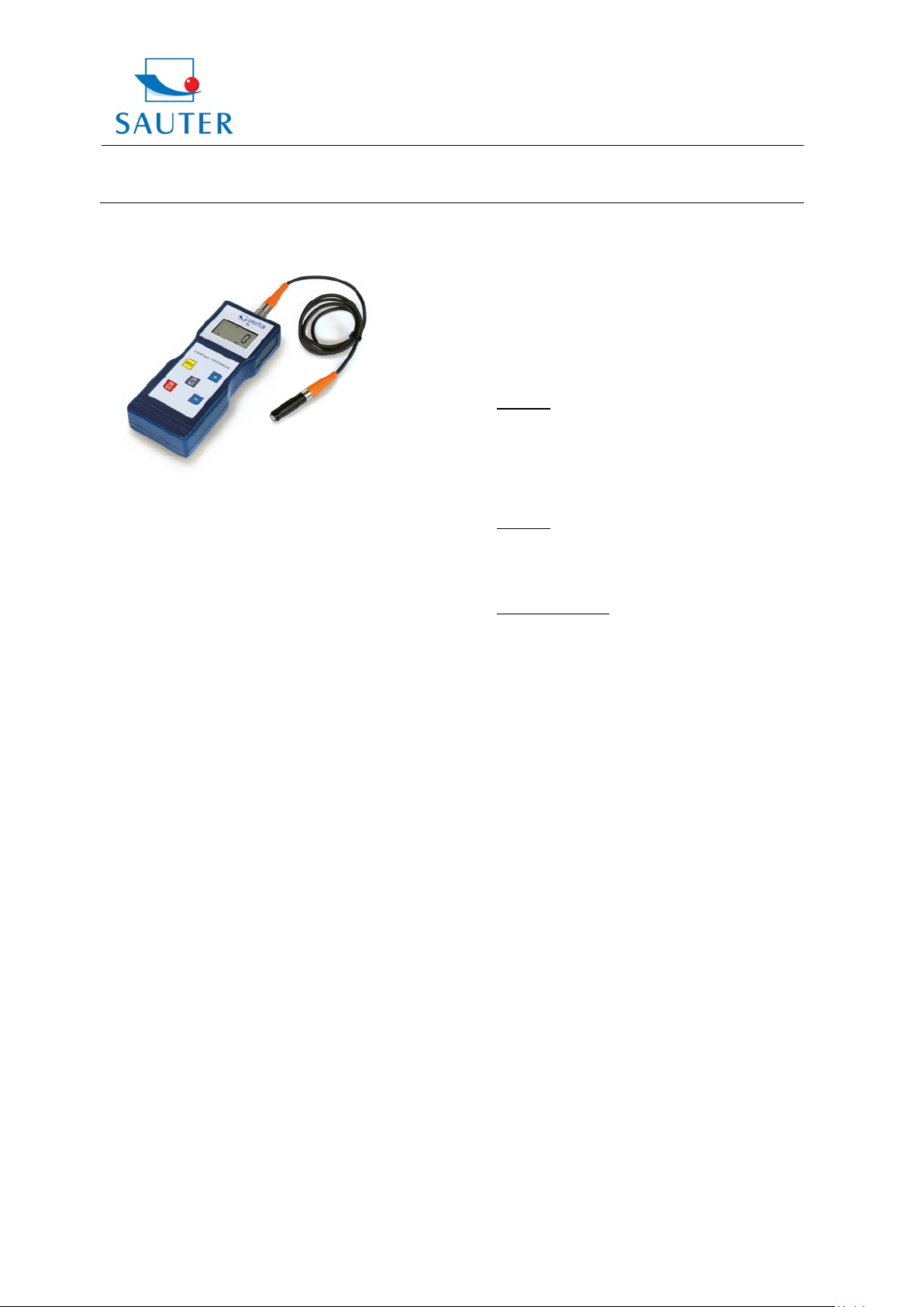
Instruction Manual
DIGITAL COATING THICKNESS GAUGE
Models: TB 1000-0 .1 F
TB 1000-0.1N
TB 1000-0.1FN
TB 2000-0.1F
Table of contents
1. Features
2. Specifications
3. Front panel descriptions
4. Measuring procedure
5. OFFSET-Accur function
6. Calibration
7. Battery replacement
8. Calibration foils
9. Correct handling of coating thickness
measurement with external sensors
10. Considerations/ Trouble-shooting
11. Declaration of conformity
Annotation: It is strongly recommended to calibrate
the new instrument before the first use, as
described in paragraph 6. By doing this it
will be achieved a much better measure ment result right from the start.
1. Features
* The instrument meets ISO standards 2178. So it can
be used in laboratory conditions as well as
under “harsh field” conditions.
* The instrument is widely used to measure the thickness
of these nonmagnetic coatings: paint, plastic & PVC,
porcelain enamel, copper, zinc, aluminium, chrome,
layers of laquer, layers of paper etc.
These coatings may be put up on following magnetic
base grounds: steel, iron, nickle, etc.
* Wide measuring range and high resolution
2. Specifications
Display: 4 digits, 10 mm LCD
Tel: +49-[0]7433-9933-199
Fax: +49-[0]7433-9933-149
Internet: www. sauter.eu
Range: 1000 μm and 2000µm
Resolution: 0.1 μm to 100 μm
1 µm over 100 µm
Accuracy:
Following accuracy is given for the models TB 1000-0.1F,
TB 1000-0.1N as wel l as TB 1000-0.1FN:
-
Standard: 3% of the measured value or min. ± 2.5 µm
Is valid within a tolerance range of ± 100 μm around the
individually measured range, if a two-point calibrat ion was
performed within this tolerance range.
For model TB 2000-0.1F accuracy is:
-
Standard: 5% of the measured value or min. ± 2.5 µm
Is valid within a tolerance range of ± 100 μm around t he
individually measured range, if a two-point calibrat ion was
performed within this tolerance range.
-
Off-Set Accur Mode: 1% of the measured value
or min. ± 1.0 µm
Is valid within ± 50 μm around the Off-Set Accur point.
All tolerances are valid after the adjustment procedure!
Power supply: 4 x 1.5V AA battery
Operating conditions:
Temperature 0 to 50 °C
Humidity ≤ 80 %
Size: 161 x 69 x 32 mm
Weight: about 260 g (including batteries)
Accessory: Carrying case
Operation manual
Instrument and sensor
Calibration foils
Base plate
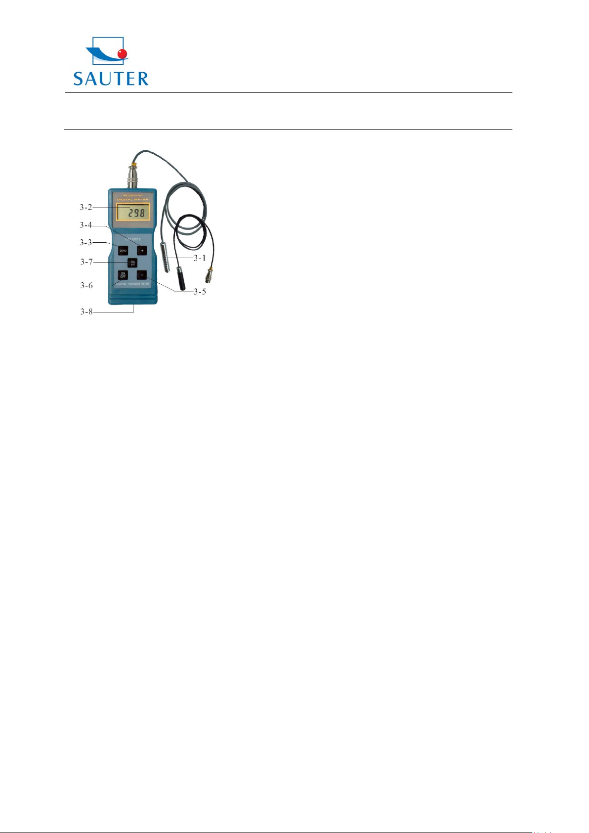
3. Front panel description
3-1 Sensor
3-2 Display
3-3 Zero- key
3-4 Plus- key
3-5 Minus- key
3-6 Power- on/ Power- off key
3-7 µm/ mil key
3-8 Battery compartment/ cover
TB-BA-e-1212 1
Page 2
Sauter GmbH
Ziegelei 1
TB
D-72336 Balingen
E-Mail: info@sauter.eu
Instruction Manual
4. Measuring procedure
4.1 The power- key is to be pressed to turn on the power.
`0` appears on the display 3-2.
Remark: The instrument will auto- calibrate, as soon
as it is switched on.
Please pay attention to the sensor. During the initial
calibration it should be neither in direct surroundings
of the base plate nor other magnetic materials.
4.2 The sensor is to be placed on the coating to be
measured.
The coating thickness is now shown on the display.
4.3 To perform the next measurement the sensor has to
be lifted for more than 1cm off the base material
and step 4.2 is to be repeated.
4.4 In case of inaccuracies to the measurement result, it
is recommended to calibrate the instrument before
measuring as described in 6.
4.5 The instrument can be switched off by the
Power- on/ Power- off key 3-6. The gauge
switches off automatically 2 minutes after the
last operation.
5. OFFSET-Accur
With this instrument the possibility is given to improve
the measurement result essentially by using the OFFSET-
Accur function. Therefore it is necessary to calibrate the
gauge with a reference coating in the typically measured
range. This adjustment can also be done with the
calibration foils, included in the delivery. Ideally this adjustment should be done on the base m aterial which is used
for the real measurement instead on the base plate
included in the delivery.
5.1 The result of the initially measurement is still shown on
the display (as performed in 4.2).
Tel: +49-[0]7433-9933-199
Fax: +49-[0]7433-9933-149
Internet: www. sauter.eu
5.2 The sensor is to be removed from the test object. Then
the reading on the display shall be corrected by
pressing the Plus- key or the Minus- key.
6. Calibration
6.1 Zero calibration: The sensor has to be placed on the
base plate or another uncoated nonmagnetic material.
On the display `0` is shown when pressing the
Zero- key.
The Zero- key may not be pressed if the sensor is not
placed on the base plate or on any other uncoated
base material.
6.2 An applicable calibration foil is to be chosen adequate
to the typical measurement range.
6.3 The chosen calibration foil has to be placed onto the
base plate or another uncoated base material.
6.4 The sensor 3-1 has to be placed carefully onto the
calibration foil and then it has to be lifted.
The result now appears on the display.
It shall be corrected by pressing the Plus- key 3-4 or
the Minus- key 3-5. For doing this, the sensor must be
removed from the base plate or the material to be
measured.
6.5 Step 6.4 is to be repeated until the measurement
accuracy has been realised.
7. Battery replacement
7.1 The batteries are to be replaced if the battery
voltage is less than 4.8V. In this case the battery
symbol ``+-`` appears on the display.
7.2 The battery cover is to be removed (Fig.1, 3-6) from
the instrument and the batteries are to be taken off.
7.3 The batteries (4×1.5V AA/UM-3) are to be installed
correctly into the case.
7.4 If the instrument is not to be used for an extended
period, batteries are to be extracted.
8. Calibration foils
As accessory the instrument includes a calibration foil
set and the base plate.
9. Correct handling of coating thickness measurement
with external sensors
The sensor has to be touched at the lower pole s egment
and it has to be pressed slightly onto the test object.
TB-BA-e-1212 2
Page 3

Sauter GmbH
Ziegelei 1
TB
D-72336 Balingen
E-Mail: info@sauter.eu
Instruction Manual
The black chequered pole segment is movably seated on a
spring. By means of the spring, the sensor tip presses onto
the test object with a defined force. This way,
measurement errors can be avoided.
Tel: +49-[0]7433-9933-199
Fax: +49-[0]7433-9933-149
Internet: www. sauter.eu
11. Declaration of conformity
It is recommendable to effect several test measurements
before the first use of the instrument. This way, further
measurement errors can be avoided.
10. Considerations / Trouble-shooting
10.1 The sensors of coating thickness gauges are to be
replaced only by identical types or series.
Otherwise the accuracy of measurement may be
affected or the gauge might be damaged.
10.2 The gauge should always be calibrated on the base
material used for the actual measurement, not on the
base plate included in the delivery.
10.3 The sensor will eventually be worn off. Its life will
depend on the number of measurements taken and
how abrasive the coating is.
.
TB-BA-e-1212 3
 Loading...