

Page 1
KERN & Sohn GmbH
Ziegelei 1
D-72336 Balingen
E-Mail: info@kern-sohn.com
Phone: +49-[0]7433- 9933-0
Internet: www.kern-sohn.com
Operating manual
KERN OEX
Version 1.1
10/2014
GB
Platform balance
Fax: +49-[0]7433-9933-149
Doc.No.OEX-BA-e-1411
Page 2
KERN OEX
Platform balance
GB
Version 1.1 10/2014
Operating manual
Contents
1 Pay attention to the instructions in the Operation Manual ............................. 3
2 Intended use for OEX balances ......................................................................... 4
3 Design of OEX balances with one weighing cell ............................................. 4
5 ATEX marking – meaning of icon ..................................................................... 7
6 Installation instruction for balance ................................................................... 9
7 Changing the installation site for the balance ............................................... 13
8 Cleaning and maintenance .............................................................................. 14
9 Technical examination ..................................................................................... 15
2 Doc.No.OEX-BA-e-1411
Page 3
1 Pay attention to the instructions in the Operation Manual
Carefully read this operation manual befor e setup and
commissioning, even if you are already familiar with
Conformity with these operating instructions is a precautionary measure for the safe
operation of IEX balances in ex-protected spaces.
Employees should familiarize themselves with the device’s components described in
the operating instructi o ns :
• Display KEX-TM
• Power unit IEX-A01-U, IEX-A01-E
These operating instru c ti ons should be freely available for consultation to the
employees.
The operating instructions contain the icons shown below:
• Continuously prescribed actions
• Actions prescribed under certain circumstances
KERN balances.
All language versions contain a non-binding
translation.
The original German is binding.
• Marking essential paragraphs dealing with explosion protec t ion
These operating instructions may be supplemented by additional warnings and safety
information provided by KERN.
All employees must be inform ed abo ut new supplements added to these oper ati ng
instructions.
Doc.No.OEX-BA-e-1411 3
Page 4
electrical part on the platform and the material used in zones 1
o
2 Intended use for OEX balances
Load in ex-protected spaces. It is possible to tare the balance over the entire working
range, thus allowing determination of the net weight.
The design of the balance (construction of non-electrical part of the platform balance
and material used) is in conformity with Directive 94/9/EE, applicable in countries of
the European Union.
• Due to their design, the balances of the IEX series can be used with
a nonand 2 where
o gasses, mixtures of gasses, vapour types IIA, IIB or IIC
o or explosive groups can develop,
as well as for temperature classes T1, T2, T3 or T4.
3 Design of OEX balances with one wei ghing cell
4 The construction of balances with one weighing cell of the IEX series is based on
the modular design principle and comprise:
• Display KEX-TM
• Power unit IEX-A01 by KERN, positioned outside the hazardous zone
• Weighing cell executed as ex-model
• Weighing platform, non-electric, mechanical balance component.
The display unit of the KEX-TM series is connected by a cable to the integrated
dynamometer (a weighing cell) of the platform. The platform bal a nc e compr is es a
weighing pan made of stainles s st eel pr oviding sufficient protecti on and al l owing
easy cleaning. The balances of the OEX series have a stainless steel weighing cell
providing advanced sturdiness against damaging influences in the ambient
conditions.
The cable used for connecting the weighing cell to the display unit is protected by a
rod or approx. 3 m long tube.
The display unit is supplied with energy by the KERN mains adapter IEX-A01
positioned outside the hazardous area. The mains adapter is plugged into the mains
power supply of 230V.
The housing of the display unit has a marked terminal for the PE conductor
(electrostatic disc harge). The housing is connected electrically to the platform
balance by a steel tube.
4 Doc.No.OEX-BA-e-1411
Page 5
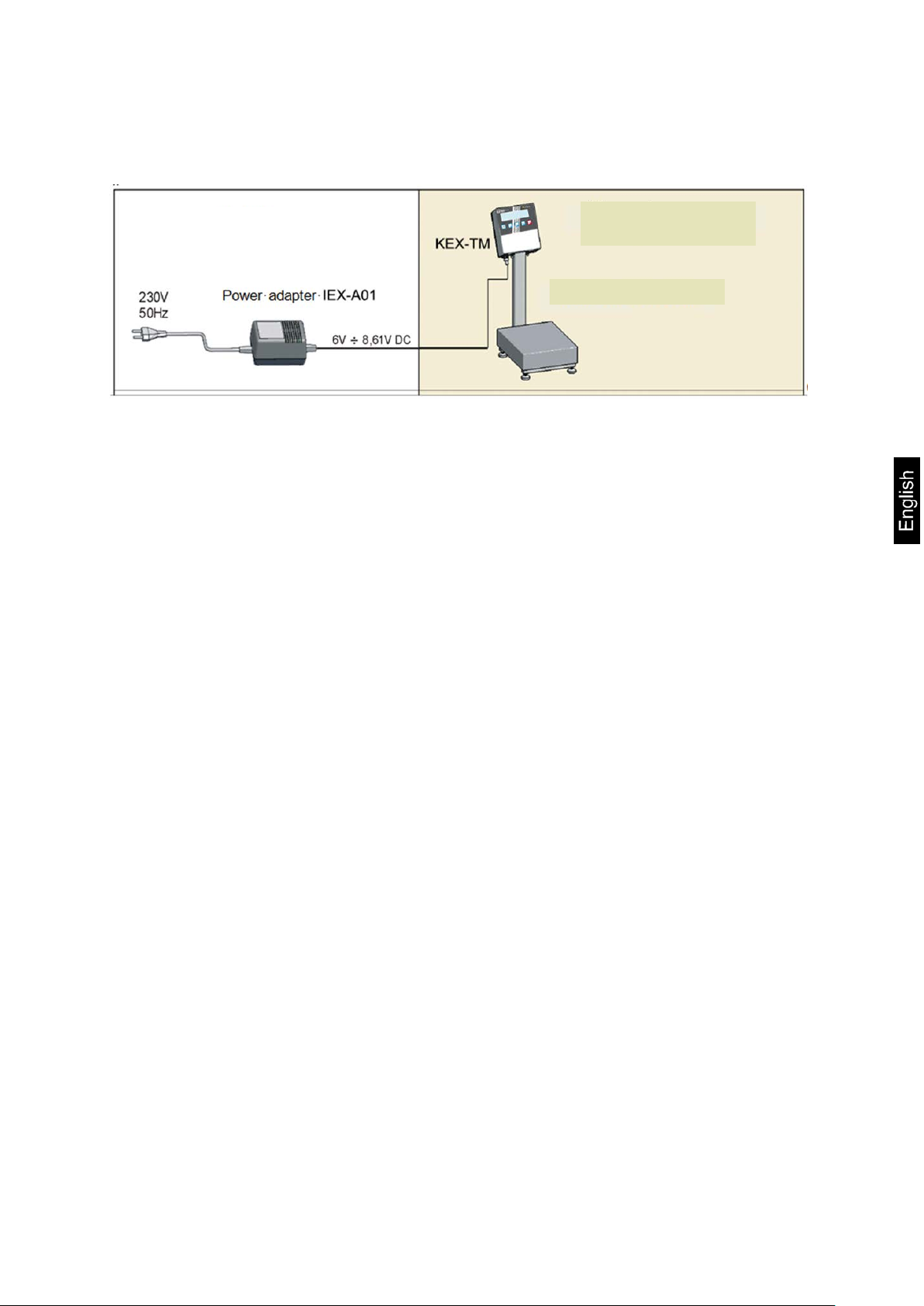
Safe area
Ex-protected area
1 load cell balance
The balances of the OEX series are equipped with a KEX-TM display unit.
Doc.No.OEX-BA-e-1411 5
Page 6

Balance model
A1
A2 B C1
C2 D E
OEX 6K-3HM
306
246
103±3
268
208
~535
~485
OEX 10K-3HM
306
246
103±3
268
208
~535
~485
OEX 30K-2HM
410
410
98±2
370
370
~617
~613
OEX 60K-2HM
500
500
150±5
400
400
~790
~710
OEX 100K-1HM
500
500
150±5
400
400
~790
~710
Balances of the OEX series - dimensions
Balance model
A1
A2 B C1
C2
OEX 6K-3M
306
246
103±3
268
208
OEX 10K-3M
306
246
103±3
268
208
OEX 30K-2M
410
410
98±2
370
370
OEX 60K-2M
500
500
150±5
400
400
OEX 100K-1M
500
500
150±5
400
400
Balances of the OEX series - dimensions
Models with tripod:
Models without tripod:
6 Doc.No.OEX-BA-e-1411
Page 7

II 2 G IIC T4
Category for group II
devices:
1
2
3
Explosive atmosphere:
G
D
Icon for explosion
protection used
Construction
type:
o
p
q
d
e
ia
ib
Electrical
equipment
compatible with
one or few types
of explosion
protection
constructions
Gas explosivity group -
Examples:
-
-
,
Temperature class – max
surface temperature of device
parts exposed to explosive
mixtures:
T1: 4500C
of gas and vapour
Safety level
Gas atmosphere:
-
-
-
Dust atmosphere:
-
-
-
5 ATEX marking – meaning of icon
• The balances of the OEX series meet the requirements of group II,
Icon declaration as per Directive 94/9/EG:
class 2 for devices in as per Directive 94/9/EU and are marked as -
.
– The device
guarantees a very
high safety level,
- for operation in
areas 0,1,2
– The device
guarantees a very
high safety level,
- for operation in
areas 1,2
– The device
guarantees a normal
safety level,
- for operation in
Area 2
The balances of the OEX series are intended for indoor and outdoor use. However,
they should not be exposed to aggressive chemical vapours, critical temperatures
and high humidity. The platform balance construction is made of stainless steel.
Doc.No.OEX-BA-e-1411 7
– Caused by gas, steam
and mist.
– Caused by dust
–
– Oil protection
– Gas
protection
with
excessive
pressure
– Sand
protection
– Flameproof
protection
– Reinforced
construction
– Intrinsically
safe
construction
for operation
in areas
0,1,2,
– Intrinsically
safe
construction
for operation
in areas 1,2,
T2: 3000C
0
T3: 200
C
0
T4: 135
C
0
T5: 100
C
IIA: Propane (T1)
IIB: Ethylene (T2)
IIC: Acetylene (T2)
Benzene (T3)
Butane (T2)
Ethyl alcohol (T2)
Hydrogen (T1)
Ga
Gb
Gc
0
T6: 85
C
Temperature class
spontaneous ignition:
T1: > 450
T2: > 300
T3: > 200
T4: > 135
T5: > 100
T6: > 85
0
C
0
C
0
C
0
C
0
C
0
C
Da
Db
Dc
Page 8

The use of equipotential bonding is
explosive gasses can be
In the case of damage to the balance, unplug the plug, disconnect
the supply cable and take the device to a safe area for interim
storage so as to prevent any possible use of the balance before
result in loss of all rights to compensation under warranty.
• Ambient temperature d ur i ng operati o n -10°C to +40°C.
• The balance must be protected against mechanical shocks and
vibrations.
• The OEX balance must be installed and operated by expert staff.
• The balance should be serviced from time to time.
• Prevent electrostatic charge. Ensure t hat the ear th c ond uc tor
(equipotential) is connected to the KEX-TM display unit at all times.
• Do not disconnect PE conductor.
only admissible where the development of
completely ruled out.
•
repair.
• The display unit KEX-TM is designed intrinsically safe and is in
conformity with the following standards: PN-EN 60079-0 and PN-EN
60079-11 certified by KDB 14ATEX0110 certificate.
• The display unit is powered by mains adapter IEX-A01 made by
KERN and positioned outside the hazardous and is in conformity
with the standards: PN-EN 60079-0 and PN-EN 60079-11, certificate
KDB 14ATEX0109.
• The platform balance is used with weighing cells PC6, PC22, PC42,
PC60 and PCB supplied by Flintec which are certified for safe use in
hazardous areas - certi fica te BS V 09 ATE X E 086X.
• All non-electrical parts of the platform balance have been
manufactured in accordance with standard PN-EN 13463-1.
• All repair and maintenance work during which the housing of the
display unit needs to be opened should be carried out by KERN
customer services. Replace subassemblies with genuine parts. The
balance must not be opened by unauthorised persons as this will
Any installation or repair work deviating from those described in this manual will
inevitably result in loss of warranty.
8 Doc.No.OEX-BA-e-1411
Page 9

Weighing cell conductor
Transport Securing
Tripod
Washer
Nut
6 Installation instr uction for balance
• Prepare the installation site for the OEX balance in a professional manner.
• Ensure that the installation site is dry, level and firm.
• The permissible operating temperate range is from -10°C to +40°C
• The floor base for the installation of the platform balance must be firm enough
for supporting the maximum weight allowed for the load plus the platform
balance.
• Balances of the OEX series without tripod have a display unit that can be
connected to the wall via a cable with the help of a holder.
• The display unit is designed for attachment to a table or for installation on a
wall with the help of a holder.
o Unpack the balance outsi de the hazardous area.
o Remove all transport locking devices after unpacking:
o Attach tripod to platform.
o Feed excess cable into the tripod.
o Lift the weighing pan and remove the transport locking device.
Doc.No.OEX-BA-e-1411 9
Page 10

Transport Securing
Weighing pan
Safe area
Ex-protected area
CAUTION!
• To prevent electrostatic charge, connect the balance to earth.
• The contact slots for the wires are marked with the icon „ “.
• Prior to transport, prepare a PE conductor for electrostatic connection to earth of
the display unit.
• The PE conductor should end in a loop that is screwed to the display unit with the
help of nuts (M4).
• To ensure that the loop is fixed permanently and in contact with the display unit,
use a lock washer.
• The PE conductor should be of yellow and green colour and provide a sectional
surface of 4mm².
The diagram below shows the balance’s connection to earth:
Place the platform balance and the display unit on the intended installation site in the
ex-area and connect it to earth.
10 Doc.No.OEX-BA-e-1411
Page 11

atmosphere.
CAUTION!
• The assembly of the display unit, installation of the platform
balance and the connection to earth must be carried out within
a time frame that rules out the risk of developing an explosive
• Place the platform balance in a level, stable place as far away as possible from
heat sources and drafts.
• Level the balance with the help of the adjustable feet and a spirit level .
• Check, whether the adjustable feet stand on the balance base.
• Ensure that the weight is evenly distributed among the feet.
• Check once again that the installation site for the balance is level. Exact flat nes s
is established when the air bubble of the spirit level is in the centre of the spirit
level ring.
• If further levelling of the platform balance is required, turn the adjustable feet of
the balance in order to adjust the heig ht.
• Check the earth contact springs between the platform balance and the weighing
pan. This ensures that the electrostatic charge is discharged from the weighing
pan.
Doc.No.OEX-BA-e-1411 11
Page 12

power supply, secure it and contact KERN customer services.
• Put the weighing pan on the platform balance.
• Position the mains adapter outside the hazardous area in which an explosive
atmosphere may be expected to be present (that is in a safe place).
• Connect the connecting cable (max. 20 m) to the mains terminal marked DC IN
on the display unit.
1. Mains connection
2. Connection cable
3. Marking PE conductor
4. Shielded load cell cable
5. Sticker power connection
• Prior to initial start-up, make sure that there is no risk of explosion –
12 Doc.No.OEX-BA-e-1411
that no explosive atmospher e is pr ese nt . If it is obvious that the
balance is not working correctly, disconnect the balance from the
Page 13

• If the balance is to be taken to another installation site carry out all
operating instructions.
• Connect the adapter to a power supply of 230V AC.
• For prolonged periods of inactivity disconnect the balance from the power supply.
• Press the ON/OFF button and hold for approx . 1 second.
• After turning on the balance will carry out a self-test.
• Afterwards the balance will change to zero display, thus indicating readiness for
operation.
• The following icons will appear:
Zero indicator
kg
Stability display
Weighing mode / weighing unit
7 Changing the installation site for the balance
the precautionary measures described in chapter 6 of these
Doc.No.OEX-BA-e-1411 13
Page 14
8 Cleaning and maintenance
• Unplug the mains plug of power unit IEX-A01.
• Check, whether the electrostatic earth connection is plugged in correctly and
make sure it is in good working order.
• Clean the balance and the housing, using a slightly moistened cloth.
Simply apply any commercially available cleaning agent available for
domestic use.
• Do not use any agents for clea ning th at may scratch the sur face
mechanically. Among other thi ngs it i s c over ed i n a c onduc tiv e c oat tha t is
important for safe operation.
• The adjustable feet of the platform balance and the shock absorbers
are made of rubber. When they are inside the hazard area, you will
have to use a slightly moistened cloth for cleaning. Moistness
protects against electrostatic charges.
• Make sure that you do not damage the earth contact springs during
cleaning. They serve as a retainer of electrostatic charge on the
weighing pan. They should be approx. 5 mm above the shock
absorbers.
• Do not clean in the presence of explosive gasses.
• The use of concentrated acids, alkaline solutions or alcohols for
cleaning purposes is prohibited.
• The same applies to the use of compressed air and high pressure
cleaning equipment.
14 Doc.No.OEX-BA-e-1411
Page 15

9 Technical examination
• Technical examinati on by expert staff is required every three
months.
The examination should include the following:
• Condition of connection to earth for balance display unit, including:
o Fastening of display housing and electrical resistance - max. 100Ω,
o Fit a flexible steel tube for the protection of the conductor leading to the
platform balance and the display unit (regular balances with “cabled”
display).
• The quality of the connection between the platform and the display unit (flexible
steel tube connecting both subassemblies).
• Damage and loss of a connection is inacceptable.
• The electrical connection between the housing and the platform – the maximum
resistance between the weighing pan (put on) should be less than100Ω.
• Stability and levelling of the balance.
Doc.No.OEX-BA-e-1411 15
 Loading...