

Page 1
Co-Planar Beam Load Cell
Co-Planar Beam Load Cell
FEATURES
• Capacity range: 7.5–250 kg
• Only 2.5–8 mm high
• Very low profile
• Aluminum construction
• IP65 protection
• 1000Ω input impedance
• Provides freedom in rectangular scale size design
• Matched output and current calibration circuitry
• Eliminates need for spyder in typical bench top scales
APPLICATIONS
• Personal scales
• Commonly used in low profile infant and adult medical
scales
• Large and medium low profile platform scales
• Airport baggage scales
• Postal scales
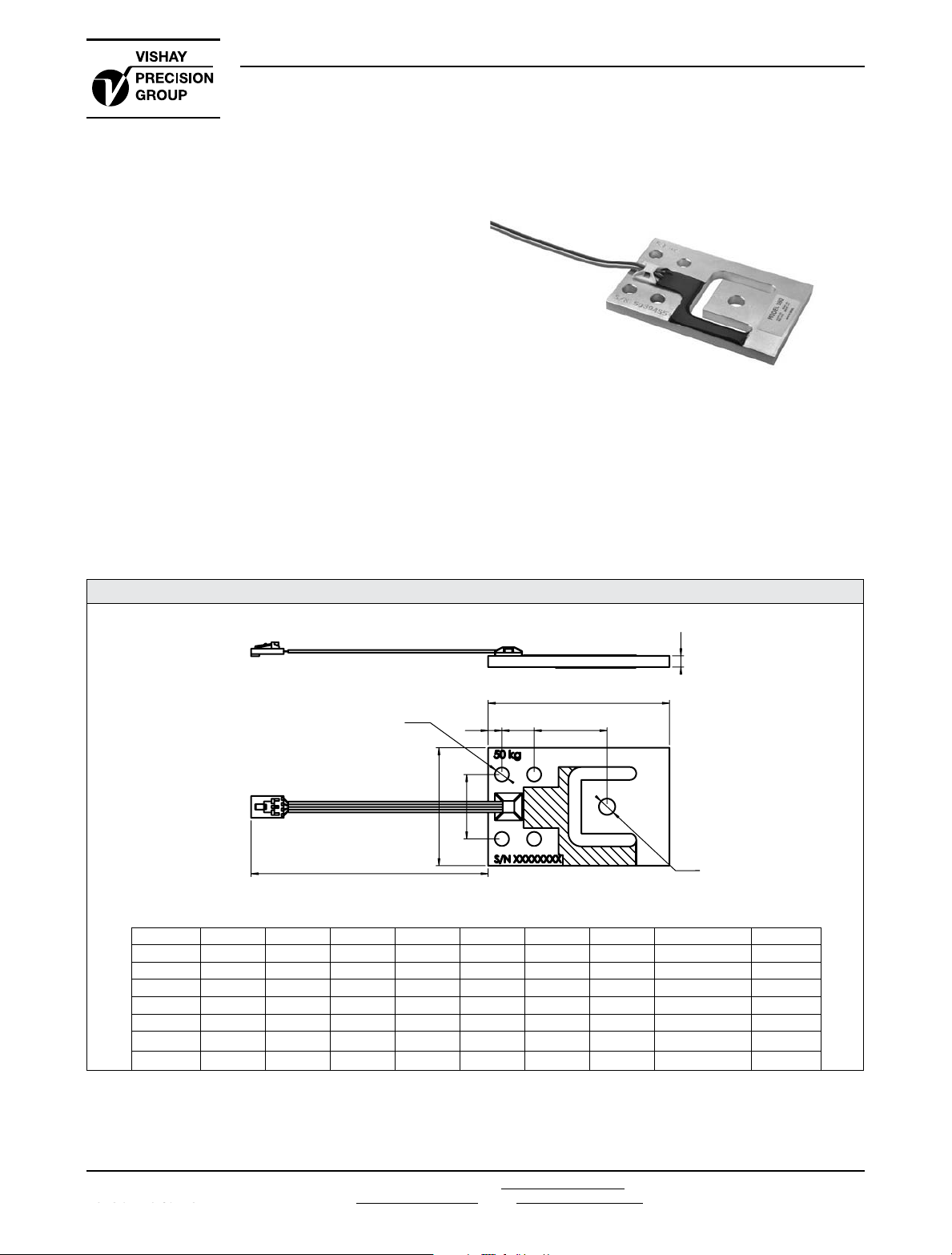
Model 380
Model 380
Tedea-Huntleigh
DESCRIPTION
Model 380 is a very low profile planar beam design,
allowing direct mounting in low profile platform scales.
The range of capacities and low profile make Model 380
most suitable for use in a wide range of applications.
OUTLINE DIMENSIONS in millimeters
H
L
ØQ2
1500.0
Type L A B C D W H Q1 Q2
PB-7.5 kg 70 14 28 4.9 27.8 39 2.5 5.1 5.1
PB-15 kg 70 14 28 4.9 27.8 39 4.1 6.2 5.1
PB-37.5 kg 76.2 15 29.3 6 30 44.5 4.8 6.2 6.6
PB-50 kg 84.5 15 34 6.4 30 55 5.3 7.6 6.6
PB-75 kg 84.5 15 34 6.4 30 55 6.4 7.6 6.6
PB-150 kg 107.5 22.8 45.9 7.8 44.5 70 8 5/16UNC 8.1
PB-250 kg 107.3 22.9 45.8 7.9 44.5 70 10.0 9.1 8.1
C
AB
W
D
ØQ1
Document No.: 12075
Document No.: 12075
Revision: 26-Jul-2012
Revision: 26-Jul-2012
Technical contact in Americas: lc.usa@vishaypg.com;
Europe: lc.eur@vishaypg.com; Asia: lc.asia@vishaypg.com
www.vpgtransducers.com
1
Page 2
Model 380
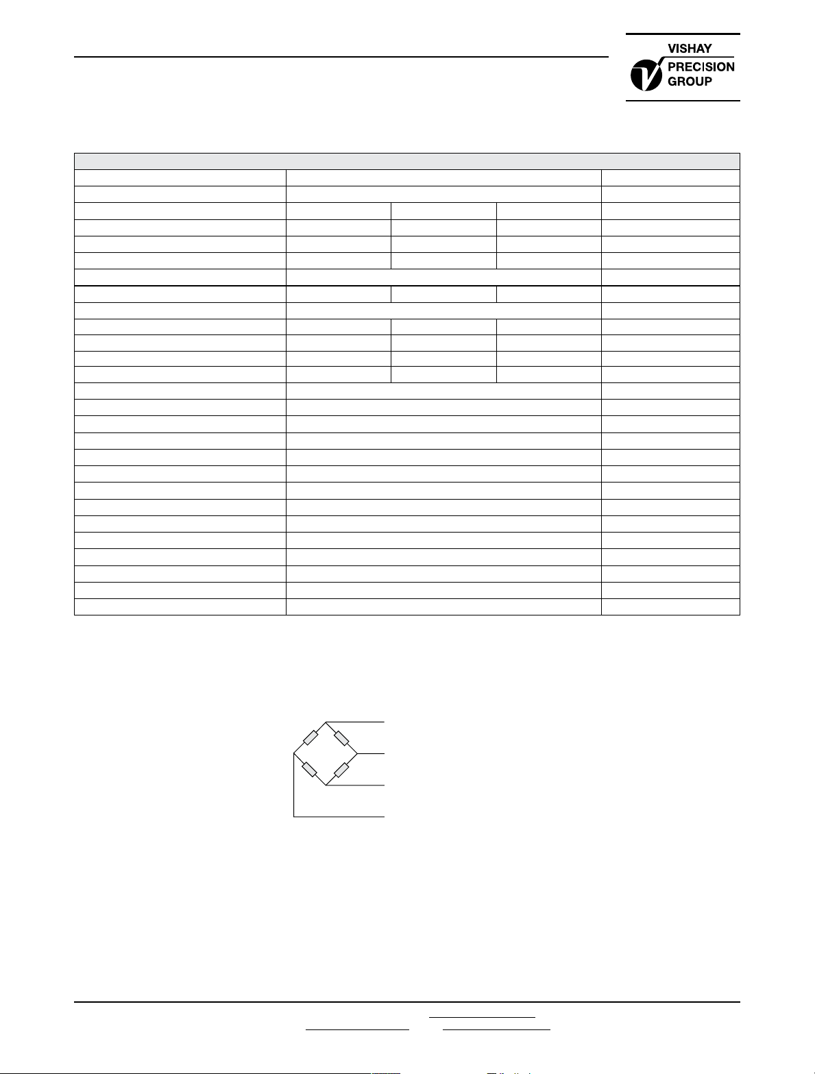
Wiring Schematic Diagram
Tedea-Huntleigh
Co-Planar Beam Load Cell
SPECIFICATIONS
PARAMETER VALUE UNIT
Rated capacity—R.C. (E
TH accuracy class E G4 H5
OIML Accuracy class NA C3 C4
Maximum no. of intervals (n) NA 3000 4000
Y = E
max/Vmin
Rated output—R.O.
Rated output tolerance
Zero balance 0.10 ±mV/V
Creep, 30 min. 0.074 0.024 0.018 ±% of load
Zero return, 30 min. 0.05 0.0167 0.0125 ±% of load
Temperature effect on output 0.002 0.001 0.00075 ±% of load/°C
Temperature effect on zero 0.007 0.00186 0.00186 ±% of R.O./°C
Input impedance 1160±15 Ω
Output impedance
Insulation resistance 5000 MΩ
Temperature range, compensated –10 to +40 °C
Temperature range, safe
Maximum safe central overload
Ultimate static overload
Safe side load
Cable type
Cable length 1.5 m
Color code +Exc: Green, +Sig: Red, -Exc: blk, -Sig: wht
Construction
Environmental protection
Outline dimensions drawing
* Consult factory for higher Y values availability
All specifications subject to change without notice.
* NA 7500* 7500*
) 7.5, 37.5, 50, 75, 150, 250 kg
max
1.0 mV/V
0.10 0.001 ±mV/V
1000±10 Ω
–30 to +70 °C
300 % of R.C.
400 % of R.C.
200 % of R.C.
4 conductors, 26AWG, flat, PVC
Aluminum, RTV potting
IP65
378.000.003
www.vpgtransducers.com
2
1
+ve Input (Green)
4
+ve Output (Red)
2
–ve Input (Black)
5
–ve Output (White)
The load cell is provided with a 4 conductor ribbon
cable and with optional AMP#103957-4 connector
Technical contact in Americas: lc.usa@vishaypg.com;
Europe: lc.eur@vishaypg.com; Asia: lc.asia@vishaypg.com
Document No.: 12075
Revision: 26-Jul-2012
Page 3

Legal Disclaimer Notice
Legal Disclaimer Notice
Vishay Precision Group
Disclaimer
Disclaimer
ALL PRODUCTS, PRODUCT SPECIFICATIONS AND DATA ARE SUBJECT TO CHANGE WITHOUT NOTICE.
Vishay Precision Group, Inc., its affiliates, agents, and employees, and all persons acting on its or their
behalf (collectively, “Vishay Precision Group”), disclaim any and all liability for any errors, inaccuracies or
incompleteness contained herein or in any other disclosure relating to any product.
The product specifications do not expand or otherwise modify Vishay Precision Group’s terms and
conditions of purchase, including but not limited to, the warranty expressed therein.
Vishay Precision Group makes no warranty, representation or guarantee other than as set forth in the terms
and conditions of purchase. To the maximum extent permitted by applicable law, Vishay Precision
Group disclaims (i) any and all liability arising out of the application or use of any product, (ii) any and
all liability, including without limitation special, consequential or incidental damages, and (iii) any and
all implied warranties, including warranties of fitness for particular purpose, non-infringement and
merchantability.
Information provided in datasheets and/or specifications may vary from actual results in different
applications and performance may vary over time. Statements regarding the suitability of products for
certain types of applications are based on Vishay Precision Group’s knowledge of typical requirements that
are often placed on Vishay Precision Group products. It is the customer’s responsibility to validate that a
particular product with the properties described in the product specification is suitable for use in a particular
application.
No license, express, implied, or otherwise, to any intellectual property rights is granted by this document, or
by any conduct of Vishay Precision Group.
The products shown herein are not designed for use in life-saving or life-sustaining applications unless
otherwise expressly indicated. Customers using or selling Vishay Precision Group products not expressly
indicated for use in such applications do so entirely at their own risk and agree to fully indemnify Vishay
Precision Group for any damages arising or resulting from such use or sale. Please contact authorized
Vishay Precision Group personnel to obtain written terms and conditions regarding products designed for
such applications.
Product names and markings noted herein may be trademarks of their respective owners.
Document No.: 63999
Document No.: 63999
Revision: 27-Apr-2011
Revision: 27-Apr-2011
www.vishaypg.com
1
 Loading...