

Page 1
KERN & Sohn GmbH
Ziegelei 1
D-72336 Balingen
E-mail: info@kern-sohn.com
Tel.: +49-[0]7433- 9933-0
Website: www.kern-sohn.com
Operating Instructions
Wheelchair scale, Transportation stretcher balance
KERN MPS_M / MTS_M / MXS_M / MWS_M
Version 1.7
03/2014
Fax: +49-[0]7433-9933-149
Personal weighing scale, Handrail scale, Bariatric scale,
GB
MPS / MTS / MXS / MWS-BA-e-1417
Page 2
KERN MPS 200K100M / PM
Transportation stretcher balance
GB
KERN MTS 300K100M
KERN MXS 300K100M
KERN MWS 300K100M
KERN MWS 400K100DM
KERN MWS 300K1LM
Version 1.7 03/2014
Operating Instructions
Personal wei ghing scale without column / with
column, Handrail scale, Bariatric scale,
Wheelchair scale/
Contents
1 Technical data ............................................................................................ 4
2 Declaration of conformity .......................................................................... 6
2.1 Explanation of graphical symbols ........................................................................... 6
3 Basic directions (general information) ..................................................... 8
3.1 Use ........................................................................................................................ 8
3.1.1 Indication ................................................................................................................................ 8
3.1.2 Contraindication ..................................................................................................................... 8
3.2 Intended use .......................................................................................................... 9
3.3 Inappropriate use ..................................................................................................10
3.4 Guarantee .............................................................................................................11
3.5 Monitoring the test substances .............................................................................11
4 Basic safety directions ............................................................................ 12
4.1 Observing the directions included in the Operating I nstructions ............................12
4.2 Personnel training .................................................................................................12
4.3 Avoidance of contamination ..................................................................................12
5 EMC guidance and manufacturer's declaration .................................... 13
6 Transport and storage ............................................................................. 17
6.1 Check upon delivery .............................................................................................17
6.2 Packaging
/ return transport ..................................................................................17
7 Unpacking, installation and sta r ting ...................................................... 18
7.1 Place of installation, place of use ..........................................................................18
7.2 Unpacking .............................................................................................................18
7.3 Installation and setting of scale .............................................................................19
7.3.1 Scope of delivery .................................................................................................................. 35
7.3.2 Installation direction for a model with wall bracket ............................................................... 35
7.4 Mains socket .........................................................................................................36
MPS / MTS / MXS / MWS-BA-e-1417 2
Page 3

7.5 Battery operation/ Rechargeable battery operat ion (optional) ...............................36
7.5.1 Battery operation .................................................................................................................. 37
7.5.2 Rechargeable battery operation (optional) ........................................................................... 39
7.6 Initial start -up ........................................................................................................41
7.7 Menu overview of verified scales ..........................................................................41
8 Operation .................................................................................................. 42
8.1 Operation elements - 20 keys of t he terminal ........................................................42
8.1.1 Display .................................................................................................................................. 42
8.1.2 Display view .......................................................................................................................... 42
8.1.3 Overview of keyboard ........................................................................................................... 43
9 Using scale ............................................................................................... 44
9.1 Weighing ..............................................................................................................44
9.1.1 Weighing with MWS ............................................................................................................. 44
9.2 Taring ...................................................................................................................45
9.3 HOLD function ......................................................................................................45
9.4 Mother/Child Function ...........................................................................................46
9.5 Determination of Body Mass Index .......................................................................46
9.5.1 Classification of BMI values ................................................................................................. 47
9.6
PRE-TARE function ..............................................................................................47
9.6.1 PRE-TARE function with 5 memories .................................................................................. 48
9.7 Printing function ....................................................................................................49
9.7.1 Parameters of RS232 interface ............................................................................................ 49
10 Error messages ........................................................................................ 50
11 Service, maintenance, disposal .............................................................. 50
11.1 Cleaning/Disinfect .................................................................................................50
11.2 Ser vice, m aint enance ...........................................................................................51
11.3 Disposal ................................................................................................................51
12 Troubleshooting ....................................................................................... 52
13 Verification ................................................................................................ 53
13.1 Adjusting ...............................................................................................................53
13.2 Adjustment key and seals .....................................................................................55
13.3 Checking the scale settings concerning scale verification .....................................57
13.3.1 Menu overview in the service mode (adjustment switch in the adjustment position) ........... 57
13.4 Validity period of verification (present status in Ger many) ....................................59
MPS / MTS / MXS / MWS-BA-e-1417 3
Page 4
MPS
200K100M/PM
MTS
300K100M
MXS
300K100M
: 14 h;
: 14 h;
: 14 h;
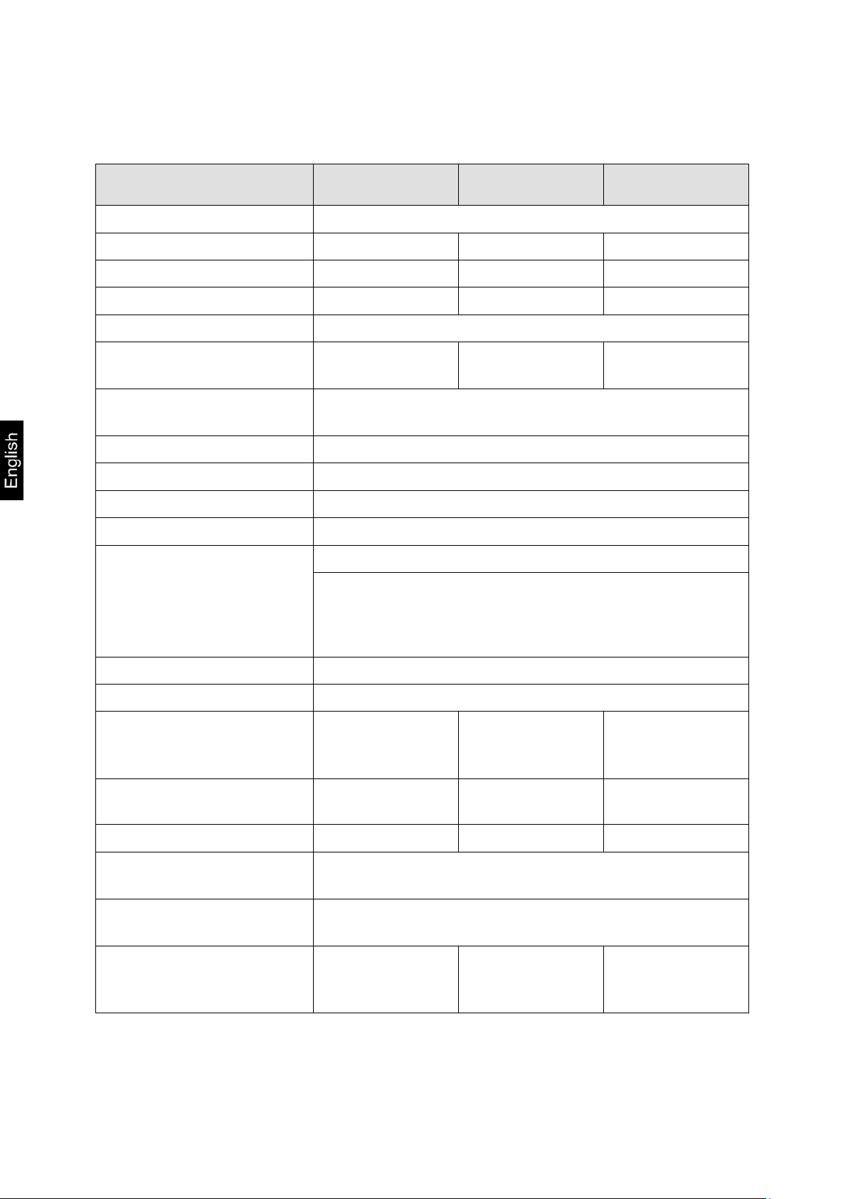
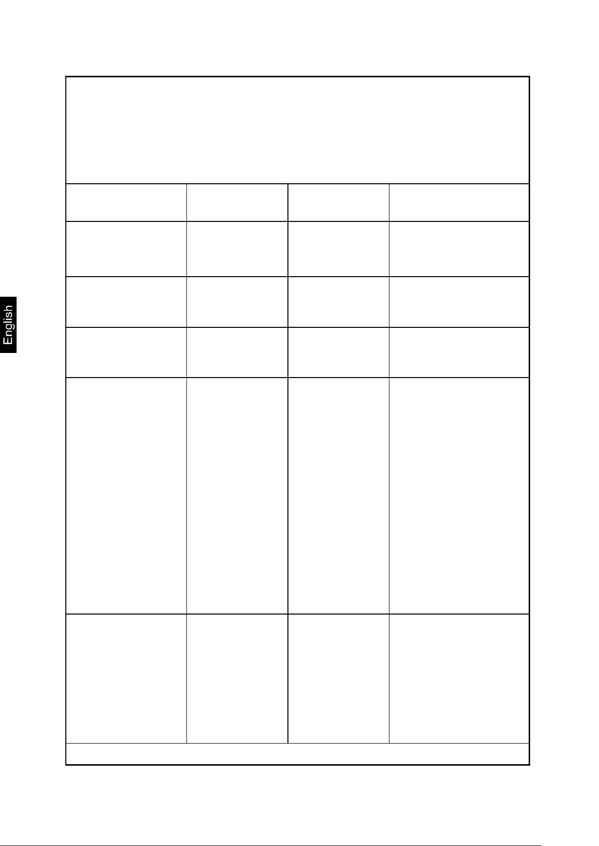
1 Technical data
KERN
Display 6-position one
Weighing range (max.) 200 kg 300 kg 300kg
Minimal load (min.) 2 kg 2 kg 2 kg
Verification value (e) 100 g 100 g 100 g
Display LCD with 25 mm high digits
Recommended calibration
weight, (class)
Signal rise time
(typical)
200 kg
(M1)
300 kg
(M1)
2–3 s
300 kg
(M1)
Warm-up time 10 min
Operating temperature +5°C …. +35°C
Storage temperature -20°C … +60°C
Air humidity max. 80% (non-condensing)
mains adapter 15 V / 300 mA (EN60601-1)
operation with 6 x 1.5 V battery supply,
Power supply
AA type batteries
operation time 50 h
Auto-Off function after 3 min without load change (possibility of setting)
Terminal (S x G x W) mm 210 x 110 x 48
Scale ready for operation
(W x D x H) mm
275 x 295 x 60
with column:
275 x 460 x 1010
550x550x1100 550x550x80
Scale plate mm
Total weight kg (net) 4.8
Verification according to
2009/23/EC
Medical device according
to 93/42/EEC
Rechargeable battery
operation (optional)
275 x 295 x 60 550x550 550x550
20.0 14.0
medical, class III
class I with measuring function
Loading time
operating time: 35 h;
7.2 V / 2000 mA
Loading time
operating time: 45h;
7.2 V / 2000 mA
Loading time
operating time: 35h;
7.2 V / 2000 mA
MPS / MTS / MXS / MWS-BA-e-1417 4
Page 5
MWS
300K1LM
MWS
300K100M
MWS
400K100DM
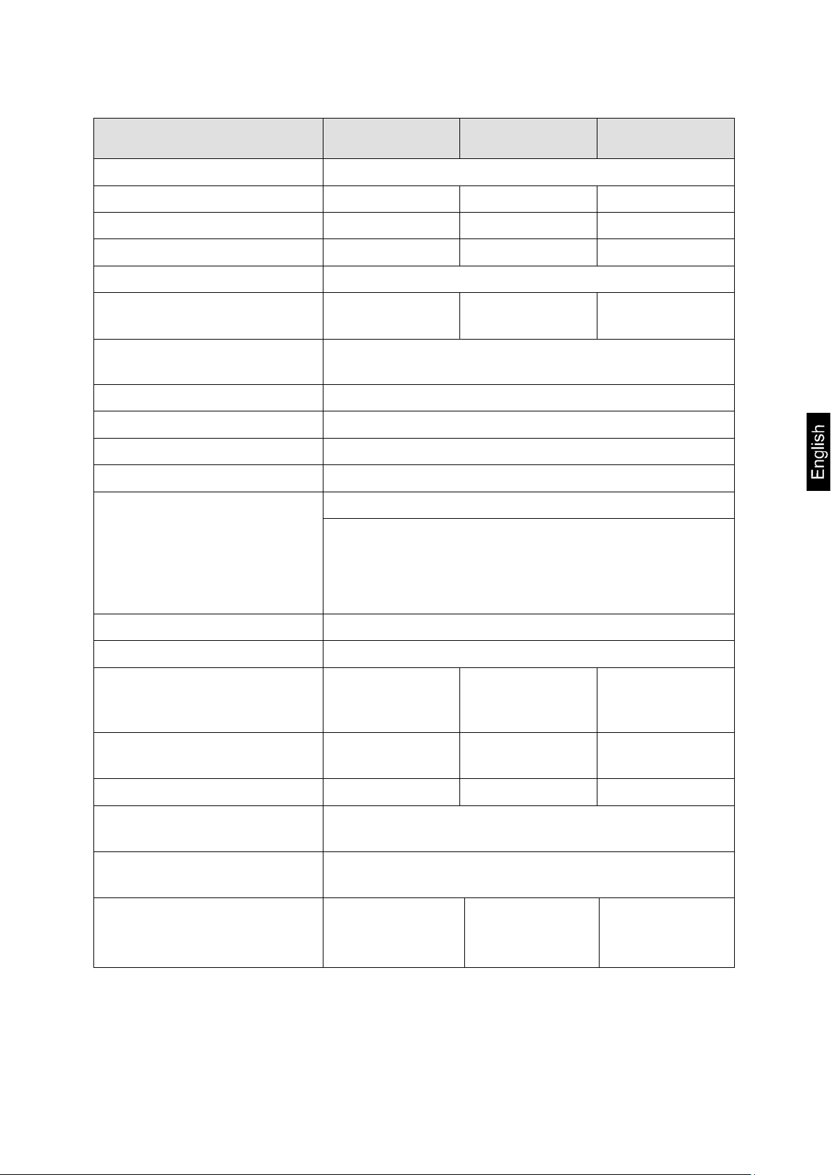
KERN
Display 6-position one
Weighing range (max.) 300 kg 300 kg 300kg; 400kg
Minimal load (min.) 2 kg 2 kg 2 kg
Verification value (e) 100 g 100 g 100 g; 200g
Display LCD with 25 mm high digits
Recommended calibration
weight, (class)
Signal rise time
(typical)
300 kg
(M1)
300 kg
(M1)
2 – 3 sec.
400 kg
(M1)
Warm-up time 10 min; 10 min
Operating temperature + 5° C …. + 35° C
Storage temperature - 20°C … + 60°C
Air humidity max. 80 % (non-condensing)
mains adapter 15V / 300 mA ( EN60601-1)
operation with 6 x 1.5 V battery supply,
Power supply
AA type batteries
operation time 50 h
Auto-Off function after 3 min without load change (possibility of setting)
Terminal (B x T x H) mm
Scale ready for operation
(W x D x H) mm
1500x860x68 1150x740x60 1250x1060x68
210 x 110 x 48
Scale plate mm 800x1200 910x740 1000x1000
Total weight kg (net) 40 26.5 39
Verification according to
2009/23/EC
Medical device according to
93/42/EEC
Rechargeable battery
operation (optional)
medical, class III
class I with measuring function
Loading time:14 h;
operating time: 45 h;
7.2 V / 2000 mA
Loading time:14 h;
operating time: 45h;
7.2 V / 2000 mA
Loading time:14 h;
operating time: 45h;
7.2 V / 2000 mA
MPS / MTS / MXS / MWS-BA-e-1417 5
Page 6
M
year
M
2 Declaration of c onf ormity
Declaration of conformity: refer to the separate document with serial number of the
device
CE marking:
2.1 Explanation of graphical symbols
This EC verification sign means that this scale is
The scales marked with this sign are permitted for
0297
0103
93/42/EEC
2009/23/EC
The directive relating to non-automatic weighing instruments
compliant with the EC Directive 2009/23/EC concerning non-automatic weighing instruments.
medical applications in European Community.
SN WY 140563 Serial number marking of each device
(located on the device and packaging) (example
number here)
Production date marking of medical devices (year
and month here as an example)
2014-03
„ Note: follow the directions included in the attached document or „Follow the Operating
Instructions”
MPS / MTS / MXS / MWS-BA-e-1417 6
Page 7
Please note operating instructions
Please note operating instructions
Marking of the medical device manufacturer with
its address
Kern & Sohn GmbH
D – 72336 Balingen Ziegelei 1
„Electro-medical equipment” with usable part of B
type
Protection class II device
Old devices do not belong to municipal waste.
They may only be delivered to collection points of
municipal waste.
+60°C Temperature limitation with lower and upper limit
(storage temperature on the packaging)
(example temperature data)
-20°C
Data concerning the scale supply voltage
9 V DC / 500 mA with indication of polarity
(polarity and example values)
MPS / MTS / MXS / MWS-BA-e-1417 7
Page 8
3 Basic directions (general information)
According to the Directive 2009/23/EC scales must be verified to the following application purposes. Article 1, paragraph 4 „Determination of
weight in the course of medical practice i.e. weighing of patients for the
purpose of health monitoring, diagnosis and medical treatment.”
3.1 Use
3.1.1 Indication
- Determination of body weight in the course of medical practice.
- Used as a „non-automatic scale” i.e. a person
• is placed carefully on the centre of the weighing plate or on a suspended balance in a suitable holding device.
• in a baby scales the baby must also be put or set on the weighing pan.
• For wheel chair scales, a wheel chair together with the person sitting in it is
pushed over the ramp into the centre of the weighing plate and/or the electric
wheel chair is moved automatically driven onto the weighing plate.
• When weighing with transportation stretchers, the person is placed with the
transportation stretcher centrically on the weighing plate.
After reaching a stable display value, the weight value can be read off.
3.1.2 Contraindication
No contraindications.
MPS / MTS / MXS / MWS-BA-e-1417 8
Page 9
3.2 Intended use
Depending on the model, the scale is used to determine the weight of standing persons, sitting persons and persons lying on a transportation stretcher and the weight
of lying babies in medical treatment rooms, as per model. The balance is suitable for
recognising, preventing and controlling illnesses.
The scales equipped with serial interface can only be connected to the
equipment compliant with EN60601-1 standard.
• On personal weighing scales, the person should step onto the centre of the
weighing platform and remain standing without moving, or on chair scales sit
in the centre of the seating surface and remain seated quietly.
• The whole wheel chair is to be pushed onto the weighing plate and/or the
electric wheel chair is to be moved automatically onto the weighing plate and
the wheels have to be fixed for weighing.
• When persons are weighed on the transportation stretcher, the whole transportation stretcher must be pushed on the centre of the weighing plate and the
wheels have to be fixed for weighing.
As soon as a stable weighing value is reached the weighing value can be read.
The weighing scale is designed for continuous duty.
MPS / MTS / MXS / MWS-BA-e-1417 9
Page 10
The scale platform can only be walked on by people that can stand on it
securely with both feet, or sit calmly (in the case of chair scale and wheel
chair scale).
Scale platforms or footrests are equipped with anti-slip material which cannot be
removed or covered when people are weighed.
When scales equipped with height measure are used, pay attention that the top flap
is always folded down after their use to avoid danger of injury.
Before any use, the scale must be checked for correct condition by an authorised
person.
When the scale doesn’t connect with the transmission cable,
please do not touch the transmission port to prevent ESD interference occurs.
3.3 Inappropriate use
Do not use the scales for dynamic weighing.
Do not leave a permanent load on the weighing plate. This can damage the measuring equipment.
Be sure to avoid impact shock and overloading the scale in excess of the prescribed
maximum load rating (max.), minus any possible tare weight that is already present.
This could result in damage of the scale.
Never operate the scale in hazardous locations. The series design is not explosionproof. Attention should be paid that flammable mixture may also be formed from
anaesthesiological means that contain oxygen or laughing gas (nitrous oxide).
Construction alterations may not be made to the scale. This can lead to incorrect
weighing results, faults concerning safety regulations as well as to destruction of the
scale.
The scale may only be used in compliance with the described guidelines. Other areas of application/planned use must be approved by KERN in writing.
MPS / MTS / MXS / MWS-BA-e-1417 10
Page 11
3.4 Guarantee
The guarantee shall become void in the event of the following:
• non-observation of our guidelines in the Operating Instructions,
• use outside the described applications,
• alteration to or opening the device,
• mechanical damage or damage caused by media, liquids,
• usual wear and tear,
• inappropriate erection or electric installation,
• overloading of the measuring equipment,
• scale falling down.
3.5 Monitoring the test substances
The metrology features of the balance and any possible available adjusting weight
must be checked at regular intervals within the scope of quality assurance. For this
purpose, the responsible user must define a suitable interval as well as the nature
and scope of this check. Information is available on KERN’s home page (www.kern-
sohn.com) with regard to the monitoring of balance test substances and the test
weights required for this. Test weights and balances can be adjusted quickly and at a
reasonable price at KERN’s accredited DKD (Deutscher Kalibrierdienst) calibration
laboratory (return to national standard).
In the case of the scales for weighing people provided with the scale to determine a
body size, it is recommended to carry out the check of its measuring accuracy because determination of the human body size is always connected with a very large
inaccuracy.
MPS / MTS / MXS / MWS-BA-e-1417 11
Page 12
4 Basic safety directions
4.1 Observing the directions included in the Ope r ating Instructions
Carefully read this operation manual before
setup and commissioning, even if you are already familiar with KERN balances.
All language versions contain a non-binding
4.2 Personnel training
The medical staff must apply and follow the operating instructions for proper use and
care of the product.
4.3 Avoidance of contamination
To avoid cross contamination (mycosis, ...), the scale plate is to be cleaned regularly.
Recommendation: after each weighing which could result in potential contamination
(e.g. when there is a direct skin contact during weighing).
translation.
The original German is binding.
MPS / MTS / MXS / MWS-BA-e-1417 12
Page 13
Guidance and manufacturer’s declaration-electromagnetic emissions
The MTS300K100M; MXS300K100M; MPS200K100M; MPS200K100PM;
Electromagnetic environmentguidance
RF emissions
Group 1
The MTS300K100M; MXS300K100M;
Class B
The MTS300K100M; MXS300K100M;
Harmonic emis3-2
Class A
Voltage fluctua-
Compliance
5 EMC guidance and manufacturer's declaration
MWS300K100M; MWS400K100DM, MWS300K-1LM is intended for use in
the electromagnetic environment specified below.
The customer or the user of the MTS300K100M; MXS300K100M;
MPS200K100M; MPS200K100PM; MWS300K100M; MWS400K100DM,
MWS300K-1LM should assure that it is used in such an environment.
Emission test Compliance
CISPR 11
RF emissions
CISPR 11
sions IEC 61000-
tions /flicker
emissions IEC
61000-3-3
MPS200K100M; MPS200K100PM;
MWS300K100M; MWS400K100DM,
MWS300K-1LM uses RF energy only for
its internal function. Therefore, its RF
emissions are very low and are not likely
to cause any interference in nearby electronic equipment.
MPS200K100M; MPS200K100PM;
MWS300K100M; MWS400K100DM,
MWS300K-1LM is suitable for use in all
establishments, including domestic establishments and those directly connected to the public low-voltage power supply
network that supplies buildings used for
domestic purposes.
MPS / MTS / MXS / MWS-BA-e-1417 13
Page 14
Guidance and manufacturer’s declaration-electromagnetic immunity
Electrostatic dis-
± 6 kV contact
± 6 kV contact
Floors should be wood, con-
Electrical fast transi-
± 2kV for power sup-
± 2kV for power sup-
Mains power quality should be
Surge IEC 61000-4-5
± 1kV line(s) to line(s)
± 1kV differential
Mains power quality should be
Voltage Dips, short inter-
<5% UT(>95% dip in
<5% UT(>95% dip in
Mains power quality should be
tery.
Power frequency(50/60
3 A/m
3 A/m
The MTS300K100M;
NOTE UT is the a.c. mains voltage prior to application of the test level.
The MTS300K100M; MXS300K100M; MPS200K100M; MPS200K100PM; MWS300K100M;
MWS400K100DM, MWS300K-1LM is intended for use in the electromagnetic environment specified
below.
The customer or the user of the MTS300K100M; MXS300K100M; MPS200K100M; MPS200K100PM;
MWS300K100M; MWS400K100DM, MWS300K-1LM should assure that it is used in such an environment.
Immunity test
charge(ESD)
IEC 61000-4-2
ent/burst IEC 61000-4-4
ruptions and voltage variations on power supply
input lines IEC 61000-4-11
Hz) magnetic field IEC
61000-4-8
IEC 60601 test
level
± 8 kV air
ply lines + 1kV for
input/output lines
± 2kV line(s) to earth
UT) for 0,5 cycle 40%
UT(60% dip in UT) for
5 cycles 70% UT(30%
dip in UT) for 25 cycles <5% UT(>95%
dip in UT) for 5 s
Compliance level
± 8 kV air
ply lines Not applicable
mode Not applicable
UT) for 0,5 cycle 40%
UT(60% dip in UT) for
5 cycles 70% UT(30%
dip in UT) for 25 cycles <5% UT(>95%
dip in UT) for 5 s
Electromagnetic environ-
ment-guidance
crete or ceramic tile. If floors
are covered with synthetic material, the relative humidity
should be at least 30%
that of a typical commercial or
hospital environment.
that of a typical commercial or
hospital environment.
that of a typical commercial or
hospital environment. If the
user of the MTS300K100M;
MXS300K100M;
MPS200K100M;
MPS200K100PM;
MWS300K100M;
MWS400K100DM,
MWS300K-1LM
requires continued operation
during power mains interruptions, it is recommended that
the MTS300K100M;
MXS300K100M;
MPS200K100M;
MPS200K100PM;
MWS300K100M;
MWS400K100DM
MWS300K-1LM
be powered from an uninterruptible power supply or a bat-
MXS300K100M;
MPS200K100M;
MPS200K100PM;
MWS300K100M;
MWS400K100DM,
MWS300K-1LM
power frequency magnetic
fields should be at levels characteristic of a typical location in
a typical commercial or hospital
environment.
MPS / MTS / MXS / MWS-BA-e-1417 14
Page 15
The MTS300K100M; MXS300K100M; MPS200K100M; MPS200K100PM; MWS300K100M;
in such and environment.
Portable and mobile RF communications
Guidance and manufacturer’s declaration-electromagnetic immunity
MWS400K100DM, MWS300K-1LM is intended for use in the electromagnetic environment specified below.
The customer or the user of the MTS300K100M; MXS300K100M; MPS200K100M;
MPS200K100PM; MWS300K100M; MWS400K100DM, MWS300K-1LM should assure that is used
Immunity test IEC 60601 test level Compliance level Electromagnetic environment-guidance
Conducted RF
IEC 61000-4-6
Radiated RF IEC
61000-4-3
3 Vrms
150 KHz to 80 MHz
3 V/m 80MHz to
2,5 GHz
3 Vrms
3 V/m
equipment should be used no closer to
any part of the MTS300K100M;
MXS300K100M; MPS200K100M;
MPS200K100PM; MWS300K100M;
MWS400K100DM, MWS300K-1LM
including cables, than the recommended
separation distance calculated from the
equation applicable to the frequency of
the transmitter.
Recommended separation distance:
d = 1,2 √P
d = 1,2 √P 80MHz to 800 MHz
d = 2,3 √P 800MHz to 2,5 GHz
Where P is the maximum output power
rating of the transmitter in watts (W) according to the transmitter manufacturer
and d is the recommended separation
distance in metres (m).
Field strengths from fixed RF transmitters,
as determined by an electromagnetic site
a
survey
, should be less than the compli-
ance level in each frequency range
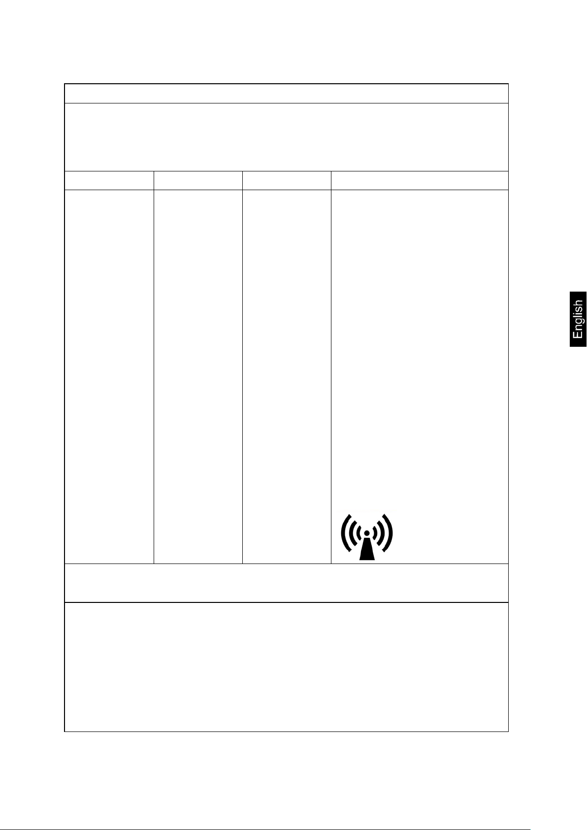
Interference may occur in the vicinity of
equipment marked with the following
symbol:
b
.
NOTE1 At 80 MHz and 800 MHz, the higher frequency range applies.
NOTE2 These guidelines may not apply in all situations. Electromagnetic propagation is affected by absorp-
tion and reflection from structures, objects and people.
a Field strengths from fixed transmitters, such as base stations for radio (cellular/cordless) telephones and
land mobile radios, amateur radio, AM and FM radio broadcast and TV broadcast cannot be predicted
theoretically with accuracy. To assess the electromagnetic environment due to fixed RF transmitters, an
electromagnetic site survey should be considered. If the measured field strength in the location in which
the MTS300K100M; MXS300K100M; MPS200K100M; MPS200K100PM; MWS300K100M;
MWS400K100DM, MWS300K-1LM
MTS300K100M; MXS300K100M; MPS200K100M; MPS200K100PM; MWS300K100M; MWS400K100DM,
MWS300K-1LM
ditional measures my be necessary, such as re-orienting or relocating the MTS300K100M;
MXS300K100M; MPS200K100M; MPS200K100PM; MWS300K100M; MWS400K100DM, MWS300K1LM.
b Over the frequency range 150 kHz to 80 MHz, field strengths should be les than 3 V/m.
should be observed to verify normal operation. If abnormal performance is observed, ad-
is used exceeds the applicable RF compliance level above, the
MPS / MTS / MXS / MWS-BA-e-1417 15
Page 16
The MTS300K100M; MXS300K100M; MPS200K100M; MPS200K100PM; MWS300K100M; MWS400K100DM,
ment.
Rated maximum output
Separation distance according to frequency of transmitter m
For transmitters rated at a maximum output power not listed above, the recommended separation distance d in
and reflection from structures, objects and people.
Recommended separation distance between
portable and mobile RF communications equipment and the MTS300K100M; MXS300K100M;
MPS200K100M; MPS200K100PM; MWS300K100M; MWS400K100DM, MWS300K-1LM
MWS300K-1LM is intended for use in an electromagnetic environment in which radiated RF disturbances are
controlled. The customer or the user of the MTS300K100M; MXS300K100M; MPS200K100M; MPS200K100PM;
MWS300K100M; MWS400K100DM,
ing a minimum distance between portable and mobile RF communications equipment (transmitters) and the
MTS300K100M; MXS300K100M; MPS200K100M; MPS200K100PM; MWS300K100M; MWS400K100DM,
MWS300K-1LM as recommended below, according to the maximum output power of the communications equip-
power of transmitter
W
0,01 0,12 0,12 0,23
0,1 0,38 0,38 0,73
1 1,2 1,2 2,3
10 3,8 3,8 7,3
100 12 12 23
MWS300K-1LM can help prevent electromagnetic interference by maintain-
150 kHz to 80 MHz
d =1,2√P
80 MHz to 800 MHz
d =1,2√P
800 MHz to 2,5 GHz
d =2,3√P
metres (m) can be estimated using the equation applicable to the frequency of the transmitter, where p is the
maximum output power rating of the transmitter in watts (W) according to the transmitter manufacturer.
NOTE1 At 80 MHz and 800 MHz, the separation distance for the higher frequency range applies.
NOTE2 These guidelines may not apply in all situations. Electromagnetic propagation is affected by absorption
MPS / MTS / MXS / MWS-BA-e-1417 16
Page 17
6 Transport and storage
6.1 Check upon delivery
Please check the packaging immediately upon delivery and the device during unpacking for any visible signs of external damage.
6.2 Packaging / return transport
Keep all parts of the original packaging for a possibly required
return.
Only use original packaging for returning.
Prior to dispatch disconnect all cables and remove
loose/mobile parts.
Reattach possibly supplied transport securing devices.
Secure all parts such as the weighing platform, power unit
etc. against shifting and damage.
MPS / MTS / MXS / MWS-BA-e-1417 17
Page 18

7 Unpacking, installation and starting
7.1 Place of installation, place of use
The scale is designed in such a way that reliable weighing results can be achieved
under normal application conditions.
By selecting the correct location for your scale, you will be able to work quickly and
precisely.
Therefore, please observe the following when choosing a place of installation:
- Place the scale on a firm, level surface;
- Avoid extreme heat as well as temperature fluctuation caused by installing the
scale next to a radiator or in the direct sunlight;
- Protect the scale against direct draughts due to open windows and doors;
- Avoid shaking during weighing;
- Protect the scale against high humidity, vapours and dust;
- Do not expose the device to extreme dampness for longer periods of time. In-
admissible bedewing (condensation of air moisture on the device) can occur if
a cold device is taken into a significantly warmer environment. In this case,
please keep the device for approx. 2 hours at room temperature after it has
been disconnected from mains supply;
- Avoid static charge build-up on the scale and people to be weighed;
- Avoid contact with water.
Major display deviations (incorrect weighing results) are possible if electromagnetic
fields occur (e.g. coming from mobile phones or radio equipment) as well as due to
static charging and instable power supply. It is necessary then to change the scale
location or remove disturbance source.
7.2 Unpacking
Carefully remove individual scale parts or the whole scale from its packaging and
position the scale in its intended working location. When the mains adapter is used,
be careful not to cause the danger of falling over the power cable.
MPS / MTS / MXS / MWS-BA-e-1417 18
Page 19
7.3 Installation and setting of scale
Personal weighing scale MPS with wall bracket:
Scope of delivery:
MPS / MTS / MXS / MWS-BA-e-1417 19
Page 20

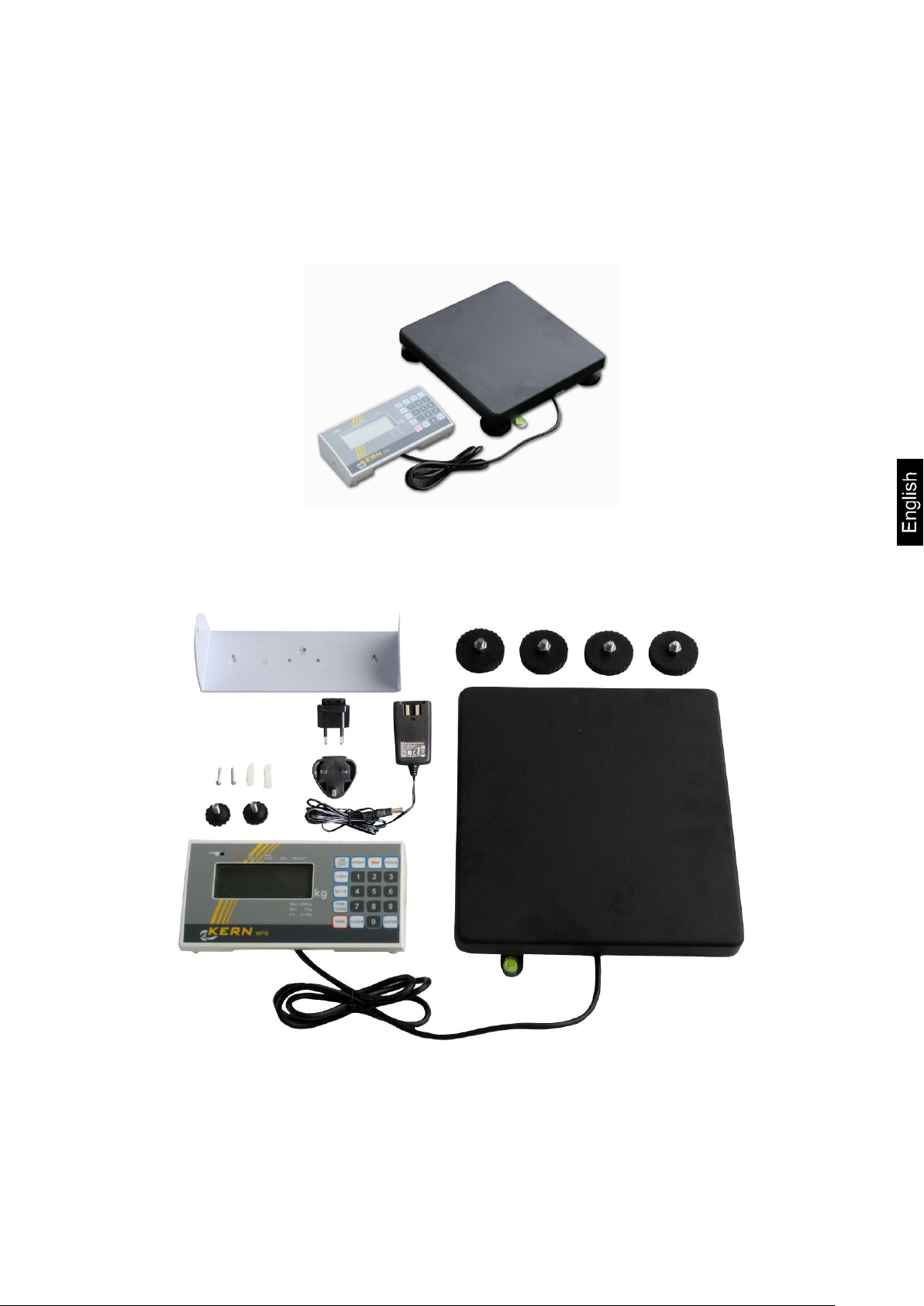
Personal weighing scale MPS-PM with column:
Scope of delivery:
• Balance with display unit and tripod
• Mains adapter
• 4 screws
MPS / MTS / MXS / MWS-BA-e-1417 20
Page 21
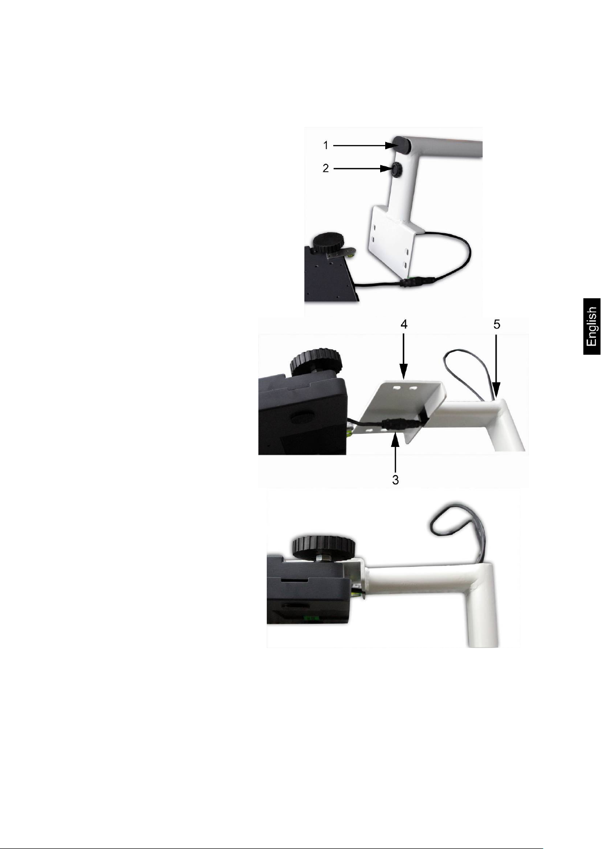
Remove cap (1)
Pull cable with Plug-in con-
Place supporting foot next to
Assembly:
Unscrew the screw (2)
nection (3) through the supporting foot (4) and pull it out
at the end (5)
the balance
MPS / MTS / MXS / MWS-BA-e-1417 21
Page 22
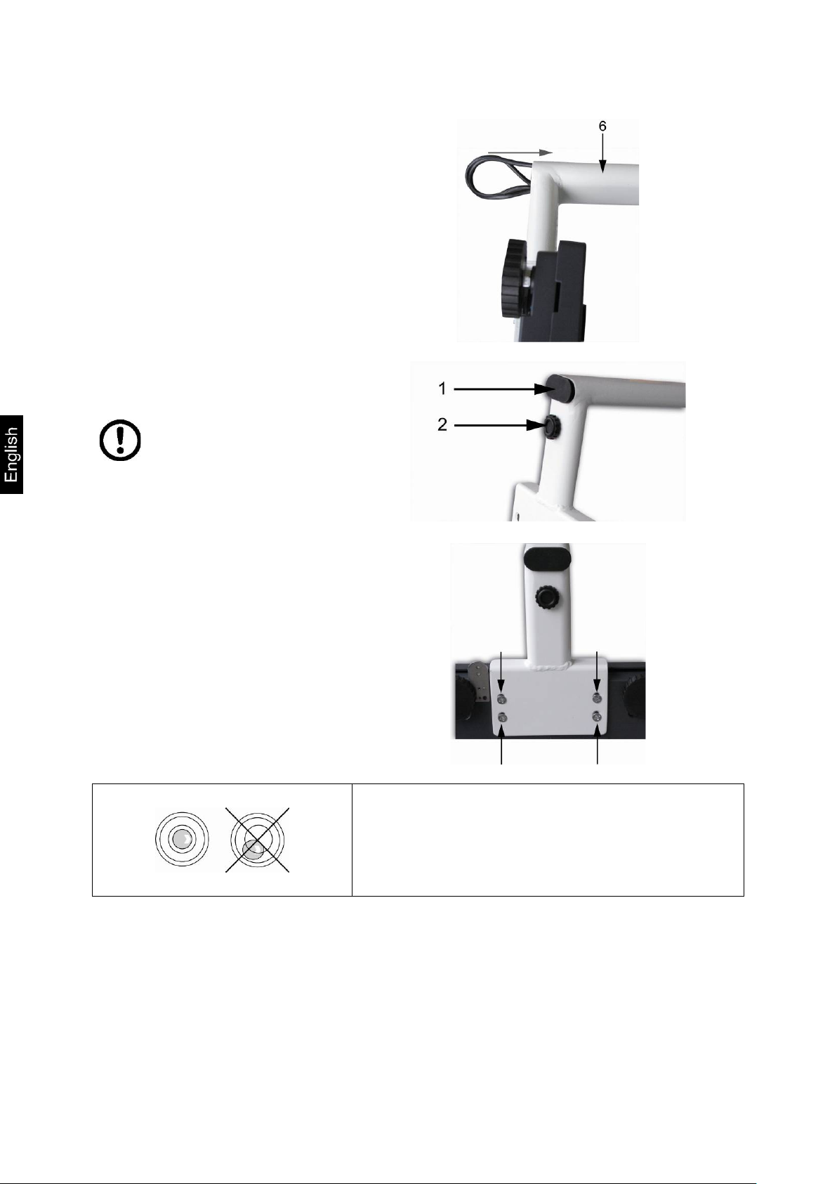
Introduce cable completely
Reinsert cap (1)
foot is not squeezed.
Use the 4 screws to attach
into the tripod tube (6)
Screw-in screw (2)
When screwing the
screw ensure that the plug-in
connector inside the tripod
the tripod to the bottom of
the balance
Level balance with foot screws until the air
bubble of the water balance is in the prescribed circle.
Check levelling regularly.
MPS / MTS / MXS / MWS-BA-e-1417 22
Page 23
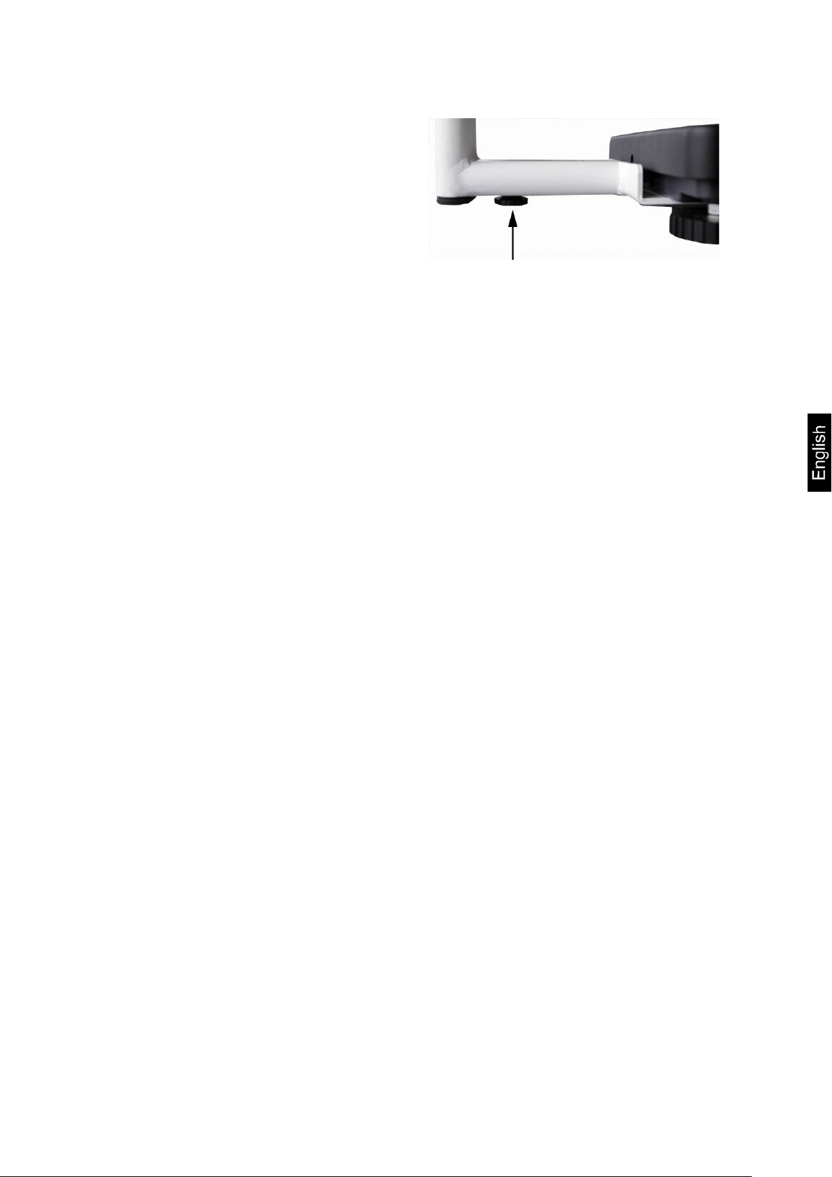
Adjust foot screw of the tripod in a
way that the tripod has a safe base
and is not loose.
MPS / MTS / MXS / MWS-BA-e-1417 23
Page 24

Mounting height measuring rod MSF 200:
How to attach to
KERN scale
Use the 2 screws for screwing the bracket into the supplied
insert nuts on the stand of the scales.
Extend the height measuring rod and tighten it in the lower
hole of the bracket with the help of the appertaining screw.
The height measuring rod can be mounted in the same way at
the back of the support stand.
MPS / MTS / MXS / MWS-BA-e-1417 24
Page 25
Scale MTS with handrail:
Scope of delivery:
MPS / MTS / MXS / MWS-BA-e-1417 25
Page 26

Assembly:
Fasten 3 corner elements to the platform, using 4 screws each time.
Place the handrail on 3 corner elements and screw it.
Fasten the terminal holder to the handrail with 3 screws.
Remove the side rubber plugs at both sides of the display.
Fasten the display to the holder with both handwheels.
Adjust the display position with handwheels.
MPS / MTS / MXS / MWS-BA-e-1417 26
Page 27

Bariatric scale MXS:
Scope of delivery:
MPS / MTS / MXS / MWS-BA-e-1417 27
Page 28

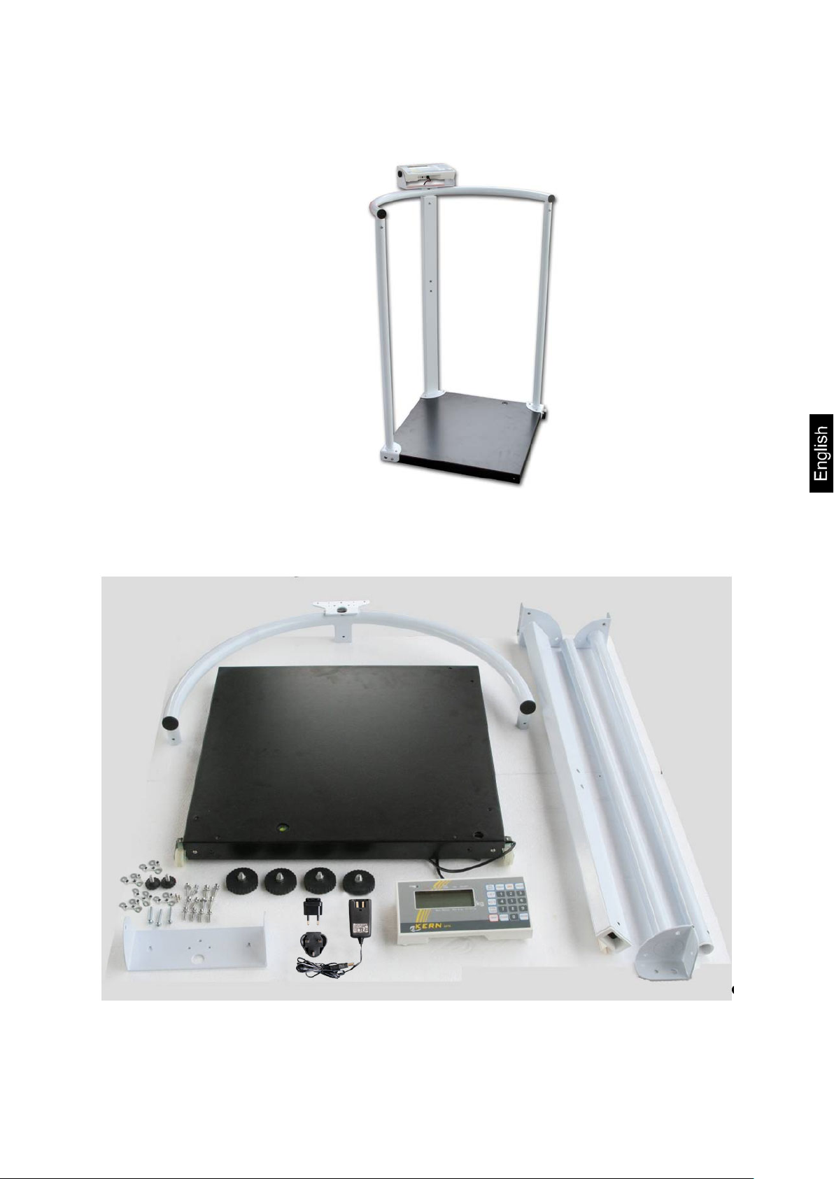
Wheelchair scale MWS:
Scope of delivery:
MPS / MTS / MXS / MWS-BA-e-1417 28
Page 29

Direction concerning installa ti on of e xternal column on MPS model without
column, MXS and MWS models
Fasten the round plate to the aluminium profile with screws.
Fasten the wall bracket to the top of aluminium profile top with screws.
Remove the side rubber plugs at both sides of the display.
Fasten the display to the bracket with both handwheels.
Adjust the display position with handwheels.
Fasten the cable with cable clips.
MPS / MTS / MXS / MWS-BA-e-1417 29
Page 30

unit)
Assembly of holding bracket set MWS-A02 at the MWS models
1
Railing
2
Handrail butts
3
Cross strut
6
Screw
7
Hexagonal socket
wrench
8
Screw
(for installation cross strut)
9
4
MPS / MTS / MXS / MWS-BA-e-1417 30
Support
5
Tapped bush
Screw
(for installation display
Page 31

We recommend engaging a second person to assist you during installation.
Carefully remove the plastic cover from
the weighing scale, ensuring that the
weighing scale does not get scratched in
the process.
Mount all 4 handrail butts (2) on the
weighing scale frame.
Ensure that the handrail butt and cable conduit are positioned to the right of
the power unit supply point. (s. fig.)
Take the two hexagonal socket wrenches (7) and fix all handrail butts with the
help of the screws 6 (3x) and the tapped
bushes 5 (2x) as shown on the illustration.
Make sure that all screws are tightened properly.
MPS / MTS / MXS / MWS-BA-e-1417 31
Page 32

Ensuring perfect fit, put the handrail containing three holes for the display unit on
the handrail butt (1) and cable conduit.
(see fig.)
Using the holders 4 (2x) fasten the handrail to the handrail butts.
Once again, use screws 6 (3x) and
tapped bushes 5 (3x).
Carry out same sequence of operations
for second handrail.
Use the two screws (8) to fasten the
cross strut (3).
Use the three screws to fasten the
mounting plate to the handrail.
MPS / MTS / MXS / MWS-BA-e-1417 32
Page 33

the installation of the application.
Take a screw driver and remove the
plastic covers from both sides of the display unit.
Screw the display unit to the handle, using the synthetic screws included in the
delivery,
The reading direction of the display unit is optional and c an be adapted during
Display unit facing inward
Display unit facing outward
MPS / MTS / MXS / MWS-BA-e-1417 33
Page 34

Using the synthetic covers, seal both
holes in the two handrail butts without
cross struts.
Once installation is complete, check all screws for tight fit. Otherwise the
person to be weighed may suffer an injury.
General direction concer ni ng setting up the previously mentioned scales
Place a personal weighing scale in the intended location and level it with the adjustable rubber feet until the air bubble in the spirit level (located in the centre of the
scale plate) is in the centre.
When scales with large and heavy platforms are installed and transported (a scale
plate folded upwards), take care not to drop a scale as this could cause its damage.
MPS / MTS / MXS / MWS-BA-e-1417 34
Page 35

7.3.1 Scope of delivery
Standard accessories:
• Mains adapter (complaint with EN 60601-1 standard).
• Operating Instructions
7.3.2 Installation direction for a model with wall bracket
(personal weighing scale, bariatric scale, wheelchair scale, transportation stretcher
scales)
MPS / MTS / MXS / MWS-BA-e-1417 35
Page 36

Connection CN 3 for
Connection CN 4 for
7.4 Mains socket
Power supply is carried out by means of the external mains adapter which also provides separation between mains and a scale. The printed voltage value must be
compliant with local voltage.
Use only admitted and original KERN mains adapters compliant with EN 60601-1
standard.
7.5 Battery operation/ Rechargeable battery operation (optional) (only models with battery operation and rechargeable battery operation)
MPS / MTS / MXS / MWS-BA-e-1417 36
batteries (AA x 6)
rechargeable battery
Page 37

off the battery cover on the lower
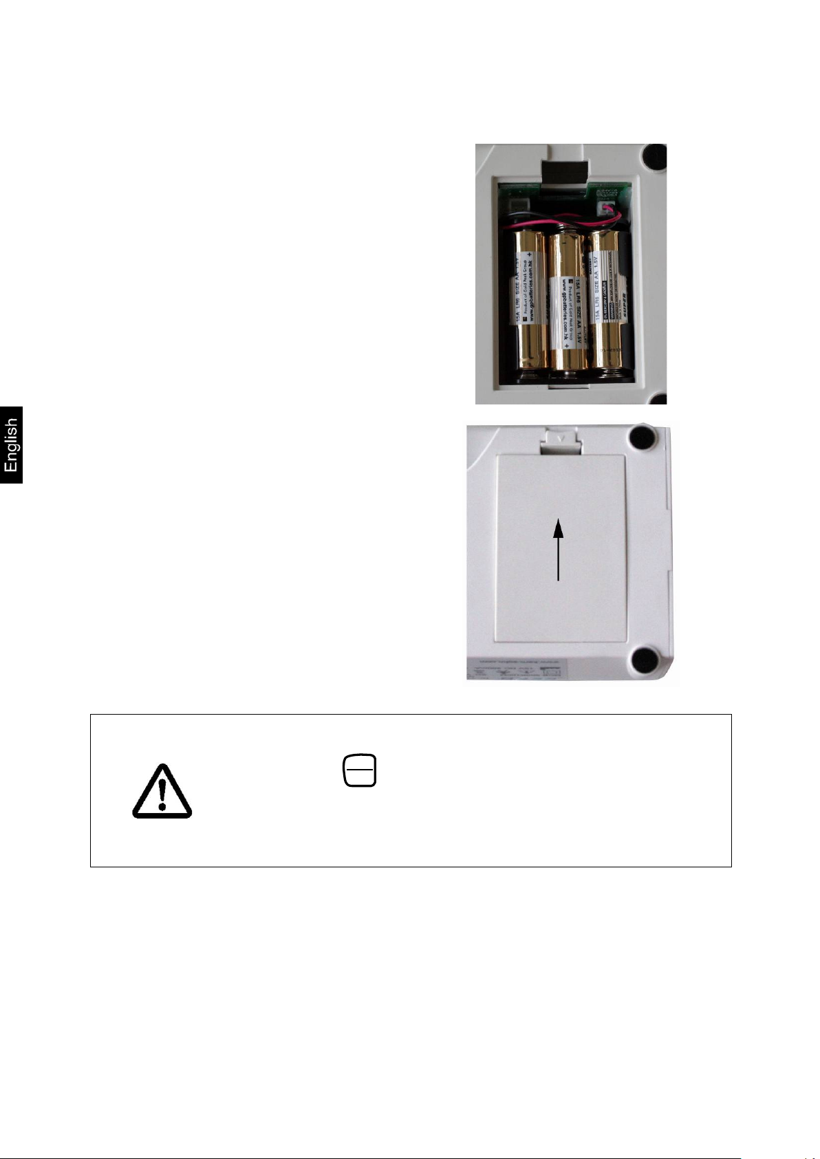
7.5.1 Battery operation
On models where the back of the display unit is not directly accessible, remove the
two black rotary knobs from both sides of the display unit in order to open the battery
compartment and remove the display unit from the holder.
Lift-
side of the balance
Carefully take out the battery holder
(1)
Insert 6 batteries (AA).
Ensure that the batteries are inserted in the correct direction
MPS / MTS / MXS / MWS-BA-e-1417 37
Page 38
Insert battery holder with the inserted
batteries into the display unit
Ensure that the cables are not
squeezed
Close the battery cover
If the batteries are run down, "LO" appears in the display. To turn
ON
off, press the
OFF
button and immediately change the batteries.
If the balance is not used for a longer time, take out the batteries
and store them separately. Leaking battery liquid could damage
the balance.
MPS / MTS / MXS / MWS-BA-e-1417 38
Page 39

off the battery cover on the lower
1
7.5.2 Rechargeable battery operation (optional)
When an optional rechargeable battery is used, proceed as follows:
On models where the back of the display unit is not directly accessible, remove the
two black rotary knobs from both sides of the display unit in order to open the battery
compartment and remove the display unit from the holder.
Lift-
side of the balance
Carefully take out the battery holder
(1)
Carefully pull-out plug (2) from the
connection CN 4 (3)
MPS / MTS / MXS / MWS-BA-e-1417 39
Page 40

Carefully insert the rechargeable bat-
tery block and insert plug into connection CN 3
Ensure that the cables are not
squeezed
Close the battery cover
If the rechargeable battery is exhausted, „LO“ is displayed. The
rechargeable battery is loaded via the provided plug-in power
supply unit (loading time 14 h for a complete loading).
MPS / MTS / MXS / MWS-BA-e-1417 40
If the balance is not used for a longer time, take out the rechargeable battery and store it separately. Leaking liquid could
damage the balance.
Page 41

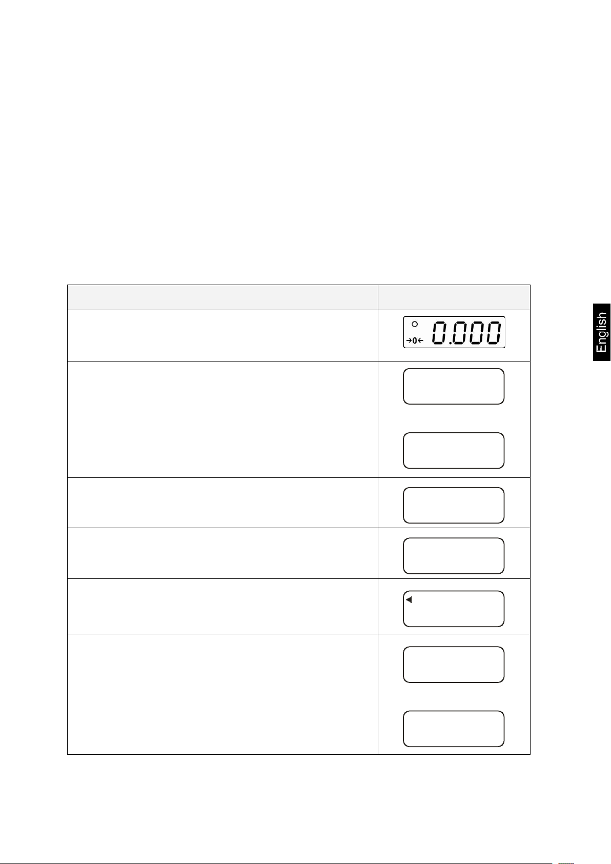
7.6 Initial start-up
0.00 kg
To obtain accurate weighing results with electronic scales, the appropriate operating
temperature is to be provided for them (refer to „Warm-up time”, section 1).
During warm-up the scale must be connected to power supply and switched on
(mains socket or batteries).
The accuracy of the scale depends on the local acceleration of gravity.
The value of acceleration of gravity is given on the rating plate.
7.7 Menu overview of verified scales
When the scale is switched on, hold the [→0←] key pressed for about 3 seconds
until the display shows successively the „SETUP” and „A.OFF” symbols.
Selection is carried out with the [TARE] and [HOLD] keys.
A.OFF = Auto off: 120 s / 180 s / 240 s / 300 sec/ OFF
bUrr = Audible signal: ON/OFF
End = Save the new setting and exiting the menu
When the „End” is selected, the setting can be finished with the [HOLD] key.
MPS / MTS / MXS / MWS-BA-e-1417 41
Page 42

Scale zero display: If the scale does not show exactly
zeroed again.
Stabilisation display:
unstable condition, the stabili sation di splay [ο] disappears.
It is illuminated when mains supply is via the mains
adaptor.
8 Operation
8.1 Operation elements - 20 keys of the terminal
8.1.1 Display
8.1.2 Display view No. Display Description
1
2
3
4 BMI
5 HOLD
[→0←]
[ο]
zero value although the scale pan is unloaded, press the
[→0←] key. After a short waiting time, the scale will be
If the display shows the s tabili sation di splay [ο], the
scale is in the stable condit ion. When the scale is in the
Calculated value of the body mass index (BMI).
Hold function / saving function is active.
MPS / MTS / MXS / MWS-BA-e-1417 42
Page 43

kg display.
6 PRE-TARE
7 NET
8 WEIGHT
Initially set tare value is active.
The net weight is displayed.
The present weight value is displayed.
8.1.3 Overview of keyboard
Key Description
ON/OFF
PRINT
BMI
Switching on/off the scale
Data transmission via interface
Determination of Body Mass Index
HOLD
Hold function / determination of stable weighing value
0 The scale is reset to 0,0
It is possible to set max. up to 2% of maximal load for
verified scales, and 2% or 100% of maximal load for
common scales (possibility of selection in the menu)
M 1-5
PRE-TARE
TARE
CLEAR
0..9
ENTER
Calling the tare function with set values
Memories 1–5 were called
Taring the scale
Clearing the digits entered manually
Entering digits
Using the entered digits
MPS / MTS / MXS / MWS-BA-e-1417 43
Page 44

9 Using scale
9.1 Weighing
Switch on the scale with the [ON/OFF] key. The diagnostic scale self-check is
performed and then the software version is displayed. The scale is ready for
weighing when the „0,00 kg” weight display is shown.
Direction: The [→0←] key makes it possible to zero the scale if necessary and
at any time.
Place a person in the middle of the scale. Wait until the stability display (ο) is
shown and then read the weighing result.
Direction:
If a person is heavier than the weighing range, the display will show the „Err” symbol
(= overload).
9.1.1 Weighing with MWS
Due to the great dimensions and the big weighing range especially suitable for
weighing of immobile patients on transportation stretchers, wheelchairs or overweight
patients in the adiposity range
9.1.1.1 Weighing with transportation stretcher or wheelchair
Place transportation stretcher/wheelchair with patient on the centre of the
scales
Arrest the brakes of the transportation stretcher/of the wheelchair
Do not leave the patient unattended
When the patient is lying/sitting quietly, read weighing value 1
Loosen the brakes and carefully pull off the transportation stretcher/wheelchair
with patient
After that weigh the transportation stretcher/wheelchair without patient and
subduct this weight from weighing value 1, from there results the patient’s
weight.
MPS / MTS / MXS / MWS-BA-e-1417 44
Page 45

9.2 Taring
The dead weight of any initial load used for weighing may be tared away by pressing
the key, so that the following weighing shows the real weight of a person to be
weighed.
E.g. when a rubber mat is put on the scale plate, the scale does not
show 0 value.
To start the taring process, press the [TARE] key. Now internal weight
saving is performed and value of 0.0 kg is displayed.
Place a person in the middle of the scale plate.
Then read the weight on the display.
Direction:
The scale can store only one tare value.
When the scale is unloaded, the saved tare value is displayed with „negative” sign.
To delete the saved tare value, unload the scale plate and then press the [TARE]
key.
9.3 HOLD function
The scale is provided with the integrated hold function (determination of average value). It enables people to be weighed accurately although they are not still on the
scale plate.
Note: Determination of average value is not possible when a person moves too
much.
Switch on the scale with the [ON/OFF] key. The diagnostic scale self-check is
performed. The scale is ready for weighing when the „0.00 kg” weight display
is shown.
Place a person in the centre of the scale plate.
Press the [HOLD] key. When the triangle is flashing on the display, the scale
takes some measuring values and then the calculated average value is dis-
played.
Press the [HOLD] key again to return the scale to the normal weighing mode.
Pressing the [HOLD] key makes it possible to activate the function at any
time.
MPS / MTS / MXS / MWS-BA-e-1417 45
Page 46

9.4 Mother/Child Function
The “Mother/Child” function makes it possible to determine the body weight of infants
and small children held in an adult’s arms.
Turn on the scales using the [ON/OFF] switch. The scales enters the self-
diagnostic mode. The device is ready for operation as soon as “0.00 kg” is
shown on the weight display.
Position the adult person in the middle of the scales platform. After showing
the stability indicator, the scales displays the person’s weight. A triangle sym-
bol is shown under the “WEIGHT” symbol.
Press the [TARE] button and the readout changes to “0.00 kg”.
Place the child in the arms of the adult person. After showing the stability indi-
cator, the scales displays the child’s weight. The triangle symbol is now dis-
played under the “NET” symbol.
Press the [TARE] button again and the readout again changes to “0.00 kg”.
After stepping off the scales, the total weight of the adult person and the child
is displayed as a negative value.
Press the [TARE] button again. The saved tare value is cancelled and the
scales can be used for weighing again.
9.5 Determination of Body Mass Index
When you obtain a stable weight and display shows 0.0 kg, place a person in the
middle of the scale plate. Wait until the weighing value is stable. Then press the BMI
key. Now enter a body height.
Please take note that reliable determination of BMI index is only possible for body
height from 100 cm to 250 cm and weight > 10 kg.
A body height entered as the last one is flashing on the display. Now you can enter a
different value with the numerical keypad. Confirm the entered value with the
ENTER key, and then a person’s BMI index will be displayed.
When the BMI index value is displayed, it is presented with the arrow pointing the
BMI symbol. To return to the weighing mode, press the BMI key once again and the
arrow at the BMI symbol will disappear.
MPS / MTS / MXS / MWS-BA-e-1417 46
Page 47

overweight
9.5.1 Classification of BMI values
Classification of weight for adults over 18 years on the basis of Body Mass Index
according to WHO, 2000 EK IV and WHO 2004 (WHO - World Health Organization).
Category BMI (kg/m2) Risk of diseases accompanying
Underweight < 18.5 low
Normal weight 18.5 – 24.9 average
Overweight
Preobesity
I degree of obesity
II degree of obesity
III degree of obesity
9.6 PRE-TARE function
When a tare weight (rubber mat, clothes, ...) is known, this value can be entered
manually.
If the PRE-TARE key is pressed shortly, the flashing display will be shown.
The PRE-TARE function is active as long as the small arrow is pointing the ”PRETARE” symbol on the display.
The value used as the last one will be displayed. If a different value is required, a
new weight value can be entered with the numerical keypad. By pressing the ENTER
key, the new value is confirmed and used. Then the entered value with minus sign
will be shown on the display.
When a person is placed on the scale plate, the display will show a weight value less
the value entered previously.
Pressing the PRE-TARE key again will return the scale to the normal weighing mode.
> 25.0
25.0 – 29.9
30.0 – 34.9
35.0 – 39.9
> 40
slightly increased
increased
high
very high
MPS / MTS / MXS / MWS-BA-e-1417 47
Page 48

9.6.1 PRE-TARE function with 5 memories
Owing to this function it is possible to store 5 Pre-Tare values (e.g. for different
wheelchairs), and then call up them if necessary.
Saving PRE-Tare values:
To enable a later calling up values from the memory, they are to be entered into the
memory first. It is carried out in the following way:
The scale plate is unloaded, and the scale display is showing 0,0 kg.
Put a weight, whose value is to be saved (e.g. an empty wheelchair), on the scale
plate and wait until a stable weight display is shown.
Press the M1-5 key repeatedly until the display will show the „ni” (M) symbol.
Press the key with digit (1..5) shortly to indicate which number a value is to be
saved under. The previously displayed weight value is flashing for 3 seconds.
When the flashing is finished, press again the key with digit previously pressed and
the weighing value is saved in the memory (short audible signal).
By pressing the CLEAR key, the scale will return to the weighing mode without
saving the value.
The display will show the real value of the weight placed on the scale plate. When
the weight is removed, the display will show 0,0 kg.
Calling up the PRE-Tare value from memory:
Press the PRE-Tare key repeatedly until the display will show the „ni” (M) symbol.
Pressing the key with digit (1..5) will display the flashing weight value saved there.
The small arrow, additionally shown on the display, is pointing to the „PRE-TARE”
symbol. By pressing another key with digit (1..5), the appropriate also flashing
weight value will be displayed. Press the ENTER key and the value will be accepted
and shown on the display as the PRE-Tare value with minus sign.
Now you can place e.g. a person in a wheelchair or on the transportation stretcher
on the scale, and only a person‘s weight will be displayed.
To return to the normal weighing mode when the scale plate is unloaded, press the
PRE-Tare key shortly again. This will also result in disappearing the small arrow
pointing the „PRE-TARE” symbol.
MPS / MTS / MXS / MWS-BA-e-1417 48
Page 49

Printing Pre-Tare memory (refer also to section 8.6):
G
88.8
kg
Gross weight
T
2.0
kg
Taring weight
N
86.8
kg
Net weight
180.0
cm
Size of patient
24.4
BMI
BMI value
To do this, press the PRE-Tare key repeatedly until the display will show the „ni” (M)
symbol.
Short pressing the PRINT key will activate printing of the values saved in 5 memories.
M1 0.0 kg
M2 7.0 kg
M3 10.0 kg
M4 30.0 kg
M5 50.0 kg
9.7 Printing function
To use this function, you need the RS232 interface cable (available as accessories)
which is connected with the round plug at the terminal back.
Note: In medical applications, only the peripheral equipment meeting EN 60601-1
standard can be connected to the interface.
When a scale is in the weighing mode, pressing the PRINT key will result in output of
the particular data, presented below, via the interface. It is the standard way to output data, which cannot be changed.
9.7.1 Parameters of RS232 interface
Set parameters of the scale interface on the connected device. It is not possible to
change the scale parameters.
Baud rate: 9600 bps
Parity check: no
Data length: 8 bits
Stop bit: 1 bit
Handshake: no or Xon/Xoff
Data code: ASCII
MPS / MTS / MXS / MWS-BA-e-1417 49
Page 50

Remove dirt immediately.
10 Error messages
The following messages can be shown on the display during switching on or using
the scale.
ERRL: Too small weight on the scale.
ooooo:
The scale plate was loaded during switching on the scale. Unload the scale
plate.
ERR: Overload, too large weight on the scale plate.
11 Service, maintenance, disposal
11.1 Cleaning/Disinfect
Weighing plate and display unit scale should be cleaned exclusively with household
cleaners or commercially available disinfectants. Follow the manufacturer’s recommendations.
Do not use any polishing or aggressive cleaning agents ( white spirit, petrol etc.) as
they may damage the high-quality surface.
To avoid cross contamination (mycosis, ...), the scale plate is to be cleaned regularly.
Recommendation: after each weighing which could result in potential contamination
(e.g. when there is a direct skin contact during weighing).
Do not spray disinfectants onto appliance.
Make sure that disinfectant does not penetrate the interior of
the appliance.
We recommend wiping disinfection.
MPS / MTS / MXS / MWS-BA-e-1417 50
Page 51

11.2 Service, maintenance
The device may only be operated and maintained by trained service technicians who
are authorised by KERN.
Disconnect the scale from mains supply before its opening.
11.3 Disposal
Disposal of packaging and device must be carried out by an operator according to
valid national or regional law of the location where the device is used.
MPS / MTS / MXS / MWS-BA-e-1417 51
Page 52

pted
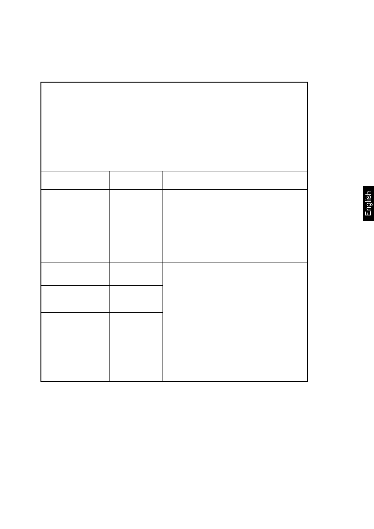
12 Troubleshooting
The scale should be switched off for a short time following an interruption in the program sequence and disconnected from mains supply. It is then necessary to repeat
the weighing process from the beginning.
Interruption Possible cause
Weight display is not illuminated.
Weight display changes
continuously
• The scale is not switched on.
• The mains supply connection has been interru
(mains cable not plugged in/faulty).
• Check the fuse of the mains adapter / green LED
is illuminated next to the fuse.
• Mains failure.
• Batteries are incorrectly inserted or discharged.
• No batteries.
• Draught/air movement
• Table/floor vibrations
• The weighing plate is in contact with foreign
matters or is installed incorrectly.
• Electromagnetic fields/static charging (choose a
different location for the scale, switch off an interfering device if possible).
The weighing result is
obviously incorrect
Should other error messages occur, switch the scale off and then on again. If the
error message remains, inform the manufacturer.
MPS / MTS / MXS / MWS-BA-e-1417 52
• The scale display is not set to zero
• Incorrect adjustment.
• Great fluctuations in temperature.
• Warm-up time was ignored.
• Electromagnetic fields/static charging (choose a
different location for the scale, switch off an interfering device if possible).
Page 53
13 Verification
SETUP
��
UNKT
��
CAL
��
K
B
CAL U ��
of the display. If not, press the [TARE] key.
CAL U
��
CAL O ��
If a scale is verified, then a verification office or manufacturer puts a verification mark
and one or several seals (seals are damaged during removal) on or in the housing.
Therefore, scale adjusting without a seal loss is not possible.
13.1 Adjusting
Observe stable environmental conditions. The warm-up time (refer to chapter 1) is
required to ensure the scale stabilisation.
Note:
In the case of verified scales, adjusting is locked with the jumper. To carry out adjusting, the jumper is to be set in the adjusting position (central position). (refer to 12.2).
Operation Display
Turn the scale on using the [ON/OFF] key.
Press and keep the [→0←] key pressed for about 3
seconds until the display shows successively the
„SETUP” and „UNIT” symbol.
Press the [TARE] key until the „CAL ib” symbol is
displayed.
Press the [HOLD] key.
Press the [TARE] key.
The triangle must be displayed at the top right side
Press the [HOLD] key repeatedly until the „CAL 0”
symbol is displayed.
MPS / MTS / MXS / MWS-BA-e-1417 53
Page 54

Press the [TARE] key, the display will show the
30770
CAL O
��
CAL 5
��
ue with the [TARE] key.
200.0
cess is started.
82077
present numerical value.
Then press the [ENTER] key.
Press the [HOLD] key.
Press the [TARE] key.
Enter the required calibration weight value (refer to
chapter 1, „Technical data”): Select the item to be
changed with the HOLD key and set its numerical val-
Confirm by pressing the [ENTER] key.
Place the calibration weight carefully in the centre of
the scale plate, and the display will show a numerical
value. Press the [ENTER] key. The adjustment pro-
When the adjustment is finished successfully, the
scale is automatically switched over to the weighing
mode again and the calibration weight value will be
displayed.
Remove the calibration weight.
Note:
In the case of verified scales, switch off a scale and set the adjustment switch in
verification position.
MPS / MTS / MXS / MWS-BA-e-1417 54
Page 55

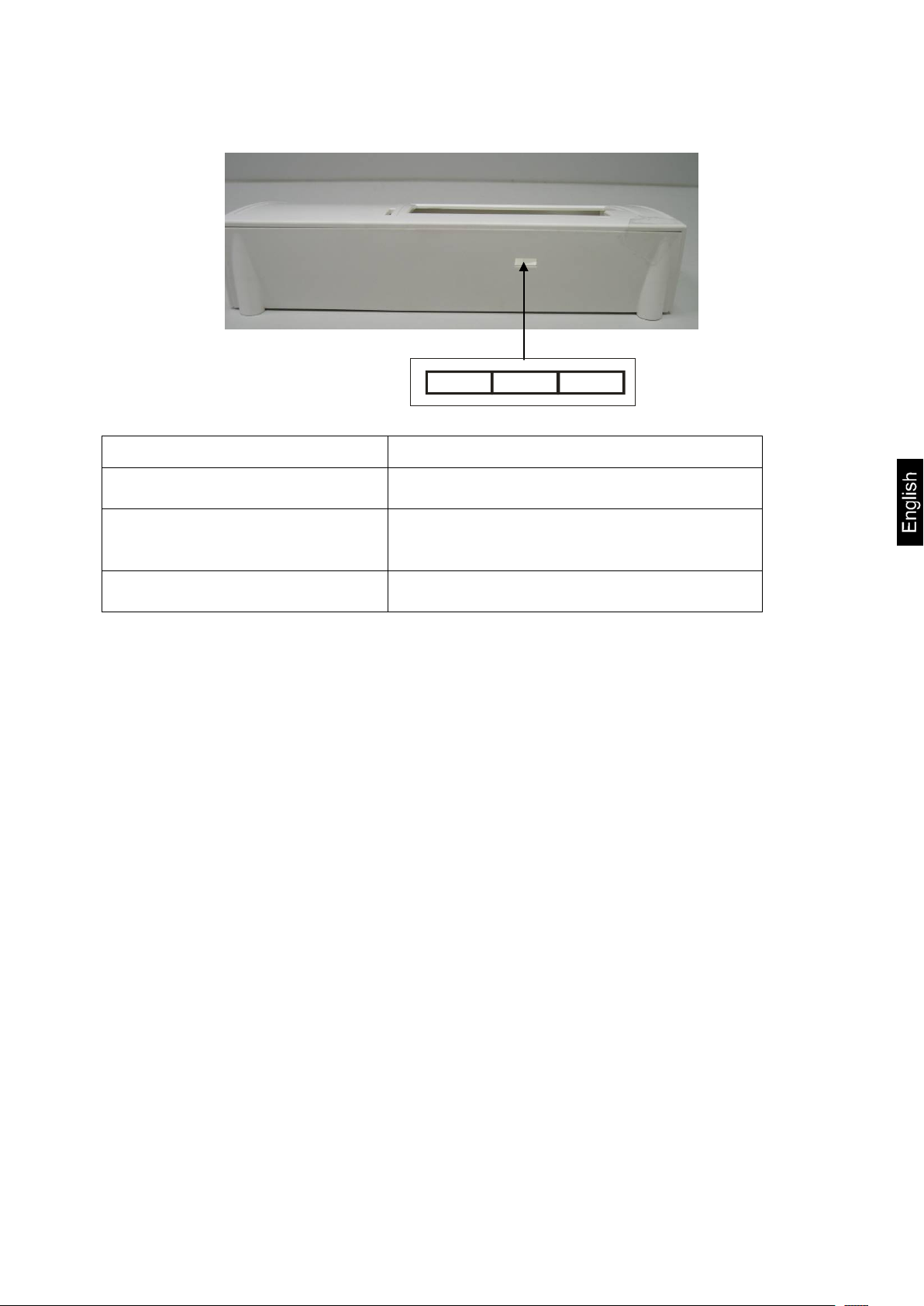
13.2 Adjustment key and seals
When verification of a scale is finished, the positions indicated on the scale are
sealed.
Verification of a scale without a seal is invalid.
Position of seals:
1. Backside 2. Battery compartment
MPS / MTS / MXS / MWS-BA-e-1417 55
Page 56
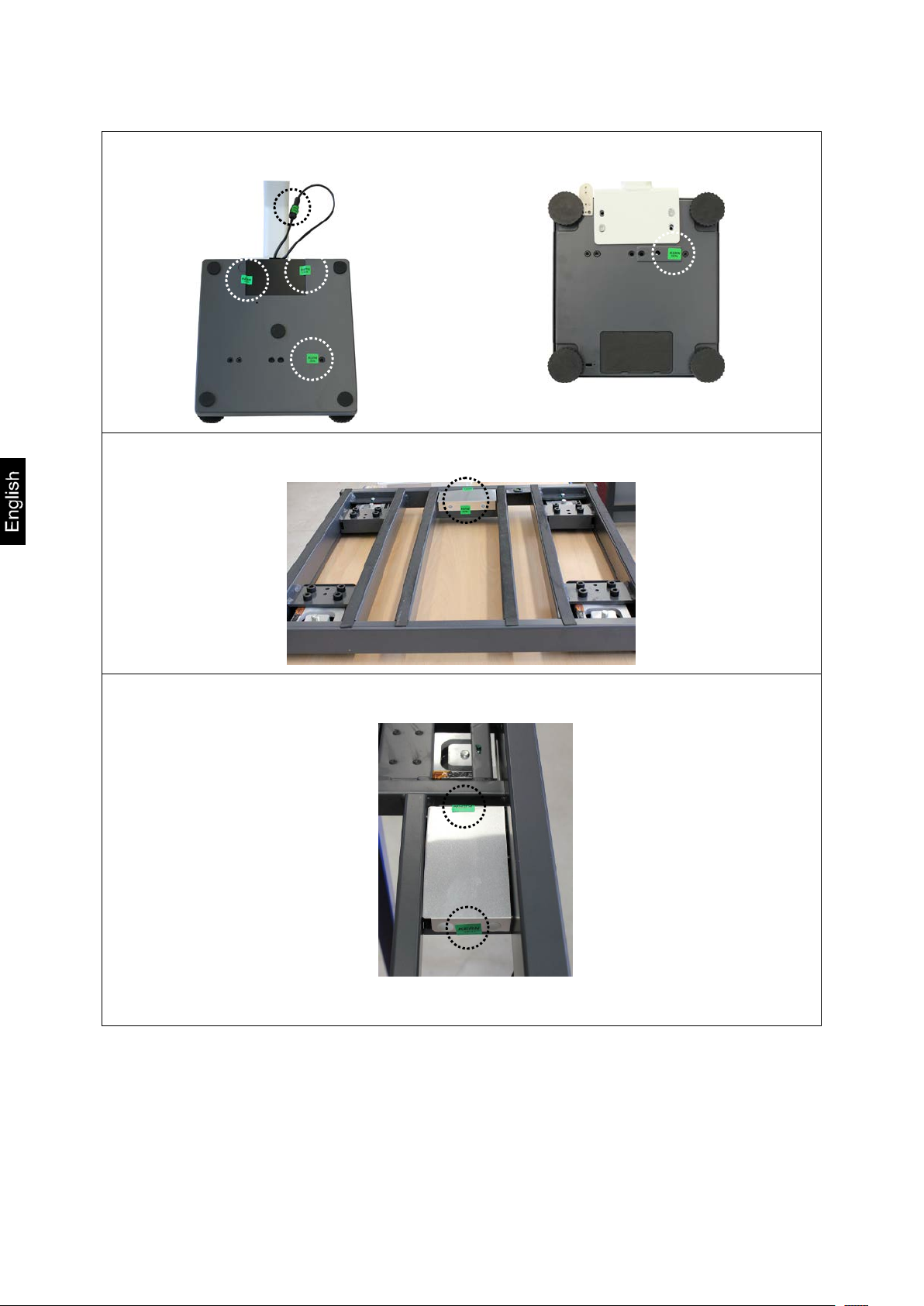
3. MPS
4. MXS, MTS
5. MWS
MPS / MTS / MXS / MWS-BA-e-1417 56
Page 57
Position of adjustment switch:
Position of adjustment switch
Status
A.OFF
BURR
1 2 3
1. left side not documented
2. centre
adjustment position - adjustment is
possible
3. right s ide verification position – adjustment locking
13.3 Checking the scale settings concerning scale verification
To start the adjustment function, a scale is to be switched over into the service
mode. To do this, set the adjustment switch in the adjustment position (refer to
chapter 12.2).
The service mode makes it possible to change all parameters of a scale. Service
parameters cannot be changed because it may have an influence on the scale
settings.
13.3.1 Menu overview in the service mode (adjustment switch in the adjustment position)
Overview is only used to check the set parameters by authorised verification offices.
Changes may only be introduced in parameters of the automatic switching off
function „
” and audible signal „
”.
MPS / MTS / MXS / MWS-BA-e-1417 57
Page 58

END
Navigation in menu:
When the scale is switched on, press and hold the [→0←] key pressed for
about 3 seconds until the display shows successively the „SETUP” and
„UNIT” symbol.
Press the [TARE] key repeatedly until the required function is displayed.
Confirm the selected function with the [HOLD] key. The first parameter will be
displayed. Select the required parameter with the [HOLD] key and confirm the
selection with the [TARE] key.
To exit the menu and save the settings, press the [TARE] key until the „
symbol is displayed and then confirm with the [HOLD] key. The scale is automatically returned to the weighing mode.
Selection is carried out with the [HOLD] and [TARE] key.
”
* Factory setting
MPS / MTS / MXS / MWS-BA-e-1417 58
Page 59

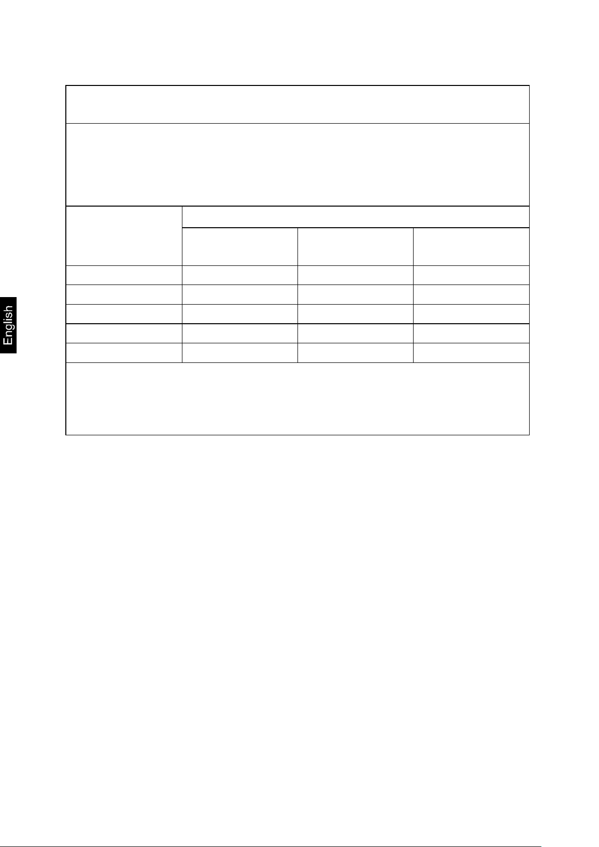
Description:
Personal weighing scales in hospitals
4 years
Personal weighing scales if placed outside hospitals
without time
Baby and mechanical scales Infant scales
4 years
Bed scales
2 years
Wheelchair scales
2 years
Weight unit: kg
Scale divisions, weighing range (max.) and read-out (d)
Selection of multi-range / single-range scale
Single-range scale
Multi-range scale
Filter: fast / normal / slow
Automatic zero tracking: 0,25 d/ 0,5 d/ 1 d/ 3 d/ OFF
Stabilisation range: 0,25 d/ 0,5 d/ 1 d/ 3 d/ OFF
Zero range: 2% / 100%
Overload range: 9 d / 2%
Adjusting
Auto off function: 120 s / 180 s / 240 s / 300 sec/ OFF
Audible signal: ON/OFF
Restoring the factory settings (default settings)
Exiting the menu
13.4 Validity period of verification (present status in Germany)
The hospitals also include rehabilitation clinics and health centres
(4-year validity of verification).
The hospitals do not include dialysis centres, care homes and consultation rooms
(verification validity without time limit).
(Data on the basis: „Verification office informs, scales in medical applications”)
MPS / MTS / MXS / MWS-BA-e-1417 59
 Loading...