

FL-BA-e-2020
Sauter GmbH
Ziegelei 1
D-72336 Balingen
e-mail: info@kern-sohn.com
Phone : +49- [0]7433- 9933-0
Fax: +49- [0]7433-9933-149
Internet: www.sauter.eu
Instruction manual digital force
gauge
SAUTER FL
Version 2.0
01/2020
GB
PROFESSIONAL MEASURING

2 FL-BA-e-2020
GB
SAUTER FL
V. 2.0 01/2020
Instruction manual digital force gauge
Congratulations on purchasing a digital force measuring device with internal or external
measuring cell from SAUTER. We hope you will enjoy your quality measuring device
with a wide range of functions. Please do not hesitate to contact us if you have any
questions, requests or suggestions.
Table of contents:
1 Introduction .....................................................................................................3
2 Scope of delivery ........................................................................................... 3
3 Additional information when using the AFH software ................................ 3
4 Technical data ................................................................................................ 4
4.1 Technical data FL with internal loadcell up to 1kN ............................................................... 4
4.2 Technical data FL with external loadcell from 2kN ............................................................... 5
4.3 Technical data external load cell (from 2kN) ......................................................................... 6
4.4 Technical Data FL TM............................................................................................................... 7
5 Battery indicator / power supply .................................................................. 8
6 Display indication .......................................................................................... 8
7 Control buttons .............................................................................................. 9
8 Functions ...................................................................................................... 10
8.1 Limit value display Good / Bad ............................................................................................. 10
8.2 Invert display .......................................................................................................................... 10
8.3 Store measured value in memory ......................................................................................... 10
8.4 Memory / Storage ................................................................................................................... 11
8.5 Diagnostics ............................................................................................................................. 12
8.6 Select Output .......................................................................................................................... 12
9 Computer control of the force gauge ......................................................... 13
10 RS232 output signal .................................................................................... 13
10.1 Interface protocol ................................................................................................................... 14
10.2 Assignment of the RS232 data interface.............................................................................. 14
11 Warnings ...................................................................................................... 15
12 Adjustment instruction FL .......................................................................... 17
13 Technical drawings ...................................................................................... 21

FL-BA-e-2020 3
1 Introduction
Please read these operating instructions carefully before commissioning, even if you
already have experience with SAUTER measuring instruments.
After receipt of the force gauge, it should be checked in advance that no transport
damage has occurred, that the outer packaging, the plastic housing, other parts or
even the gauge itself have not been damaged. If any damage is evident, please
notify SAUTER GmbH immediately.
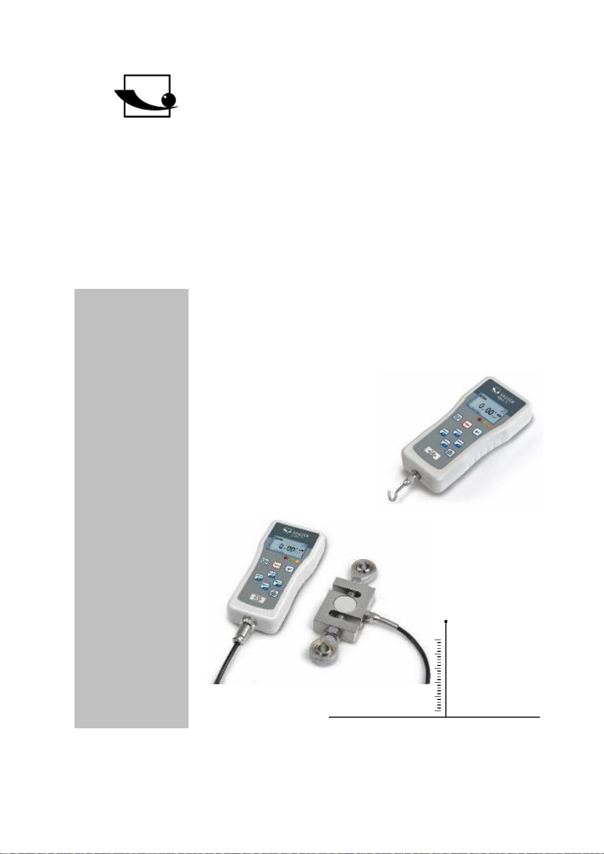
The FL can measure tensile and compressive forces very accurately and it is easy to
operate. It can be held in the hand for measurements or mounted on top of a suitable
test stand.
SAUTER offers optional software and accessories to make the measuring instrument
more versatile in use. Please ask SAUTER or the SAUTER supplier or visit our
website www.sauter.eu.
2 Scope of delivery
• SAUTER FL, incl. internal battery
• Transport case
• Battery charger
• 5 pieces M3 x 8 screws for mounting on SAUTER test benches
3 Additional information when using the AFH software
If you want to connect an FL with the combination test bench and software (AFH-LD
or AFH-FD) to a PC, you must connect the FL to the equipment port of the test bench
via the FL-A04 cable (Sub-D 9-pin to PS2) and connect the test bench to the PC via
the computer port.

4 FL-BA-e-2020
4 Technical data
4.1 Technical data FL with internal loadcell up to 1kN
Measuring
device
FL 5
FL 10
FL 20
FL 50
FL 100
FL 200
FL 500
FL 1K
Capacity
5N
10N
20N
50N
100N
200N
500N
1000N
Measurement
uncertainty
±0.2% of Max (measuring range)
Work
temperature
15°C to 35°C
Relative air
humidity
15% to 80% Humidity
Weight
(without
accessories)
Approx. 500g
Dimensions
Display unit
(LxWxH)
160x75x30mm
Thread
M6

FL-BA-e-2020 5
4.2 Technical data FL with external loadcell from 2kN
Measuring
device
FL 2k
FL 5k
FL 10k
FL 20k
Capacity
2000N
5000N
10000N
20000N
Measurement
uncertainty
±0.2% of Max (measuring range)
Working
temperature
15°C to 35°C
Relative air
humidity
15% to 80% Humidity
Weight display
unit
Approx. 500g
Dimensions
display unit
(LxWxH)
160x75x30mm
6 FL-BA-e-2020
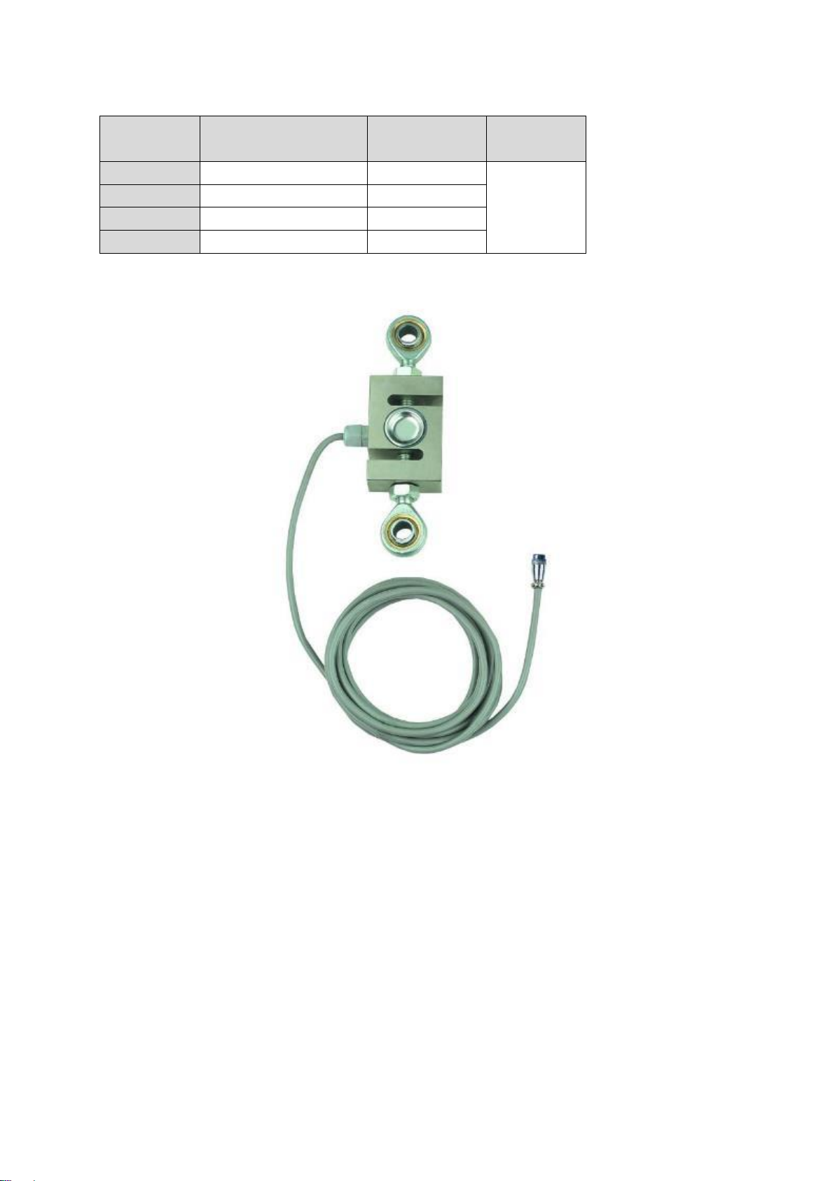
4.3 Technical data external load cell (from 2kN)
Maximum
load
LxWxH
Thread type
Cable
length
2 kN
76x51x19mm
M12x1.75
Approx.
2,5m
5 kN
76x51x28mm
M12x1.75
10 kN
76x51x28mm
M12x1.75
20 kN
76x51x28mm
M12x1.75
FL-BA-e-2020 7
4.4 Technical Data FL TM
4.4.1 Sensors
Sensor must be ordered separately. Service FL-C01 necessary.
4.4.2 Load cell connection
Solder the cable from the measuring cell to the supplied connector. The pin
assignment at the connector is as follows:
Pin 1: Supply ( - )
Pin 2: Signal ( + )
Pin 3: Signal ( - )
Pin 4: Supply ( + )
Pin 1: EXC ( - )
Pin 2: Signal ( + )
Pin 3: Signal ( - )
Pin 4: EXC ( + )
Adjustable
measuring
ranges
5N; 10N; 25N;
50N; 100N;
250N; 500N
1kN; 2,5kN; 5kN;
10kN; 20kN;
50kN
Characteristic
value max.
1mV/V
2mV/V
Measurement
uncertainty
±0,2% bis 1% von Max
(Messbereich), abhängig von
verwendetem Sensor
Working
temperature
15°C bis 35°C
Weight display
unit
Ca. 500g
Dimensions
display unit
(LxWxH)
160x75x30mm

8 FL-BA-e-2020
674
2
3
5 8 1
5 Battery indicator / power supply
Battery level > 4.8 V
4.8 V > Battery level > 4.7 V
4.7 V > Battery level > 4.4 V
4.4 V > Battery level > 4.0 V
Battery level < 4.0 V
• If the battery voltage is less than 3.9V, a message appears that the battery
is exhausted and the device switches off automatically
The FL is equipped with four Nickel Metal Hybrid (NiMH) batteries type AAA. For
safety reasons during transport, the batteries are supplied uncharged. For maximum
battery life, we recommend that you charge the batteries only with the original
charger (supplied) for a period of 14-16 hours before using the meter for the first
time.
6 Display indication
Position
Description
1
Measurement result
2
Display mode (track, peak (pull), peak (push)
3
Display of the direction of force
4
battery charge indicator
5
Number of occupied memory locations
6
Activated pass-fail criterion
7
Display unit of the measurement result
8
Force diagram

FL-BA-e-2020 9
7 Control buttons
MENU/ESC:
• Opens the menu window with the individual submenus
• By pressing the MENU/ESC button in the menu, you can return to the previous
page
ZERO (zeroing):
• Zeroing the display in track mode (tare function)
ENTER:
• Confirm the selection in the menu
• Saving a measured value in PEAK mode
PRINT (print function):
• Output of the memory contents to PC or printer
RESET (delete function):
• Delete the current PEAK value
UNIT (units of measurement):
• Press the key briefly: Switch between N, gf, kgf, ozf, lbf, mN
Mode (mode change):
Assignment with three functions:
• Track mode (continuous measurement)
• Peak Mode Train
• Peak Mode Print
ON / OFF:
• On / Off button (press button for approx. 1 s)

10 FL-BA-e-2020
8 Functions
8.1 Limit value display Good / Bad
LED display for good / bad tests
Colour
Function
Red
Exceeding the upper limit value
Green
Indicates that the pass-fail criterion has been
reached
Yellow
Falling below the lower limit value
An upper and a lower limit value can be programmed. The measuring instrument
compares the measurement result with the limit values and outputs the result as a
signal in red or green light diodes.
Setting of the limit values see MENU →PASS-FAIL
With the left arrow key the cursor is moved to the desired value. With the UP or
DOWN key the value can be changed. By pressing and holding one of these keys,
scrolling is possible. With the right arrow key the unit can be changed. With the
ENTER-key the settings are saved and you return to the main menu.
The display now shows a "PF".
The PASS-FAIL option is automatically disabled if the upper and lower limits are set
to 0 Newton. The lower value must also always be smaller than the upper one.
8.2 Invert display
The display can be rotated by 180°. To do this, do the following:
When the power is off, press and hold the "MENU/ESC" key. In addition, the "On/Off"
key is pressed and the unit switches on, thus rotating the display.
8.3 Store measured value in memory
Any measured value can be stored in the memory at any time by pressing the
ENTER key. A maximum of 500 readings can be stored.

FL-BA-e-2020 11
8.4 Memory / Storage
The memory is used to view the stored data. It can store 500 readings. Currently,
individual entries or all entries can be deleted, or the measurement data of the
memory can be printed out.
To enter the MEMORY menu, the MENU/ESC button must be pressed. Use the UP
or DOWN button to move the cursor to MEMORY. Then confirm with the ENTER
button and you are on the memory page. Press the ESC button to return to the main
menu page.
With the arrow keys UP and DOWN the page can be changed within the memory and
by pressing and holding one of these two keys it is possible to scroll up or down.
By pressing the PRINT key, the memory contents can be printed out via the serial
port.
By pressing the ZERO button, the DELETE menu is accessed
Use the UP and DOWN arrow keys to select the desired delete option. If NO is
selected here and confirmed with the ENTER key, the meter returns to the memory
page.
When DELETE is selected and the ENTER button is pressed to confirm, the currently
stored measurement is deleted and the instrument returns to the memory page.
When DELETE ALL is selected and the ENTER button is pressed to confirm, all
stored measurements are deleted and the instrument returns to the memory page.

12 FL-BA-e-2020
8.5 Diagnostics
This function is used to check the loadcell. If it is suspected that the loadcell has
been overloaded, the status can be determined immediately.
To do this, place the device in a horizontal position on a flat surface and call up the
main menu page. To enter the DIAGNOSTIC menu, the MENU/ESC button must be
pressed. Use the UP or DOWN button to move the cursor to DIAGNOSTIC and
confirm with the ENTER button. You are now on the DIAGNOSTIC page.
Press the ESC key to return to the main menu page.
If the percentage drop is between 5% - 10%, please contact the supplier to have the
loadcell replaced. These values are given as a guide only. The actual need for
calibration/replacement of the loadcell varies with its individual characteristics.
8.6 Select Output
With this option the used data output, RS 232 or USB is selected.
There is an analog output on the device. This generates a signal that goes from +2V
to -2V. This signal is a percentage of the maximum value of the force gauge. FOR
EXAMPLE..: FL100 50N is measured in the direction of pull, then a -1V signal is
applied to the analog output. 75N in compression direction, then + 1.5V is present at
the analog output. If the instrument is in PASS - Fail mode, 2V for PASS and 0V for
FAIL are present at the analog output.

FL-BA-e-2020 13
9 Computer control of the force gauge
With the RS 232 interface a connection from the force gauge to the PC can be
established by sending RS232 commands.
RS232 command
Action
"„m“
Change measuring mode
"„u“
Change measuring unit
"„z“
Set device to "zero
"„r“
Perform reset on the device
10 RS232 output signal
The reading of the FL shown on the display can be transferred to the PC by pressing
the PRINT button or by issuing a command instruction to the force gauge from the
PC.
RS232
command
Action
"“l”
Send the direct reading with unit
"“p”
Send peak value (on pull) with unit
"“c”
Send peak value (on pressure) with unit
"x" or
pressing
PRINT KEY
- Send the direct reading with unit if the current mode is
the track mode
- Send peak value (on pull) with unit if the current mode
is peak mode
- Send peak value (on pressure) with unit if the current
mode is the peak value print mode
"“d”
Send save
"“!”
Send information about the device such as model,
capacity, serial number, firmware check, original offset,
current offset, overload counter

14 FL-BA-e-2020
10.1 Interface protocol
RS-232 Parameters
- Baud rate: 9600
- Data bit: 8
- Parity: none
- Stop bit: 1
- Start bit 1
The measured value is requested by the ASCII character "9".
The returned measured value looks like this:
e.g. 0011.70 means -11.70 Newton if Newton is set
|_______ > first character describes the sign (0 = minus = pressure; 1 =
plus = pull)
| |____>-------- the remaining 6 digits describe the measured value as ASCII
character string
or: 1021.15 means +21.15 N (tractive force)
10.2 Assignment of the RS232 data interface
Pin
Signal
Illustration
2
TxD
Data output
3
GND
Ground
6
RxD
Input for control signal

FL-BA-e-2020 15
11 Warnings
Incorrectly performed force measurements can lead to serious injury to persons and
damage to objects and must therefore only be performed by trained and experienced
personnel.
In particular, it must be avoided that forces act on the purchased measuring
instrument which exceed the maximum load (Max) of the instrument or which do not
act axially via the external and internal load cell; or if high impulse forces act on the
measuring instrument.
Avoid twisting the loadcell, otherwise it could be damaged and the measuring
accuracy will decrease in any case.
Inappropriate use
Do not use the measuring instrument for medical weighing.
If small quantities of the material to be measured are removed or added, incorrect
measurement results may be displayed due to the "stability compensation" in the
measuring instrument! (Example: Slow flow of liquids out of a container suspended
from the measuring cell).
Do not apply a continuous load to measuring instruments with external measuring
cell.
Overloads
Please prevent the measuring instrument from being overloaded beyond the
specified maximum load (Max), minus any tare load that may already be present.
This can damage the measuring instrument (danger of breakage!)

16 FL-BA-e-2020
Attention:
• Make sure that never let people or objects
are under the load, as it injures
or could be damaged!
• The measuring instrument is not suitable for weighing people, do not use it as an
infant measuring instrument!
• The measuring device does not comply with the German Medical Devices Act
(MPG).
• Never operate the measuring instrument in rooms where there is a risk of
explosion. The standard version is not explosion-proof.
• The design of the measuring instrument must not be changed. This can lead to
incorrect measurement results, safety-related defects and the destruction of the
measuring device.
• The measuring instrument may only be operated or maintained by trained
personnel.
• The measuring instrument may only be used in accordance with the described
specifications.
• SAUTER must give written approval for any other areas of use / applications.
Warranty
The warranty is void if
• Non-compliance with our guidelines of the operating instructions
• Use outside the described field of application
• Modifying or opening the device
• mechanical damage and damage caused by agents such as liquids or liquids
have been caused
• improper assembly or electrical installation
• Overloading the measuring cell
Test equipment monitoring
As part of quality assurance, the metrological characteristics of the measuring
instrument and any test weight that may be present must be checked at regular
intervals. The user responsible must define a suitable interval for this purpose as well
as the type and scope of this inspection.
Information on the monitoring of measuring instruments and the necessary test
weights is available on the SAUTER homepage (www.sauter.eu). The weights and
measuring instruments can be checked and adjusted quickly and at favourable prices
in KERN's accredited DAkkS laboratory (traceability to the national standard).
Note:
To view the CE declaration, please click on the following link:
https://www.kern-sohn.com/shop/de/DOWNLOADS/

FL-BA-e-2020 17
12 Adjustment instruction FL
Introduction:
This manual describes the adjustment procedure, although some programming
modes are password protected.
Important! During the adjustment procedure, all weights for loading the sensor should
be calibrated.
Tempering:
Before the measuring instrument is handed over to the calibration laboratory, the
respective instrument must be checked for possible damage and the order
specification.
Before starting adjustment, allow the measuring instrument to reach the working
temperature of the calibration laboratory for at least 2 hours.
Preparation:
Insert a full set of charged batteries in the battery compartment or connect a standard
power supply
Calibration:
1. Switch on the measuring instrument
2. Select the main menu by pressing the MENU key and select the menu function
CALIBRATION with the cursor keys UP and DOWN. Then press the ENTER key.
The ENTER PASSWORD window will appear on the screen.
ENTER PASSWORD [Enter password].
4 FIGURES
PASSWORD: 0000*
* Master password = 7780
Use the UP and DOWN arrow keys to scroll up and down. The left and right arrows
can be used to select the left and right positions. To change a digit, press and hold
for a moment.
Press the ENTER key to confirm the password. If the password is correct, the display
shows the calibration menu window.

18 FL-BA-e-2020
CALIBRATION MENU
1) MAXIMUM LOAD
2) VOLTAGE INCREASE
3) COMPRESSION GAIN
4) SET NEW PASSWORD
3. Select the correct value of the weight for the respective measuring instrument. To
set the load, use the UP and DOWN arrow keys to select the MAX CAPACITY
menu function and press ENTER. The menu window for setting the maximum
load appears on the screen.
SETTING MAX. LOAD 1/2
SETTING MAX. LOAD 2/2
4. Use the UP and DOWN arrow keys to select the maximum load, press the
selected value and hold for a moment.
Press the ENTER key to save the selected value. Then return to the calibration
menu.

FL-BA-e-2020 19
5. To calibrate in the voltage direction: use the UP and DOWN arrow keys to select
TENSION GAIN in the calibration menu and then press ENTER. The display
shows a menu window for voltage increase.
5.1. Zero voltage
• Set up the measuring device together with the necessary accessories for
performing the voltage calibration
• apply a force of 100% of the meter's power to the weight
• Remove the load, leave the device standing
• as soon as the display becomes stable, press the ZERO key to save the zero
display
5.2. maximum stress
• apply the voltage force of 100% of the meter power
• Calibrate the voltage increase with the UP and DOWN arrow keys and RIGHT
and LEFT until the meter displays the maximum voltage result
• touch the ENTER key to save the results for the entire voltage scale.
6. Compression calibration: In the calibration menu, use the UP and DOWN arrow
keys to select the COMPRESSION GAIN menu function and then press ENTER.
The display will show a menu window for compression gain.

20 FL-BA-e-2020
6.1. Zero Compression
• Set up the measuring device and all necessary accessories for performing the
compression calibration
• apply a force of 100% of the meter's power to the weight
• Remove the load, leave the device standing
• as soon as the display becomes stable, press the ZERO key to save the zero
display
6.2. maximum compression
• apply the compression force of 100% of the gauge power
• Calibrate the compression gain with the UP and DOWN arrow keys and
RIGHT and LEFT until the meter displays the maximum compression result
• touch the ENTER key to save the results for the entire compression scale
7. After successful calibration, remove all accessories from the meter and place the
meter on a flat surface with its backside facing up.
Select the voltage increase menu window, press the ZERO key to obtain the
primary calibration offset, date and time and reset the overload counter.

FL-BA-e-2020 21
13 Technical drawings
M8
 Loading...