

Page 1

FC 1K-BT-BA-e-2020
Sauter GmbH
Ziegelei 1
D-72336 Balingen
e-mail: info@kern-sohn.com
Phone : +49- [0]7433- 9933-0
Fax: +49- [0]7433-9933-149
Internet: www.sauter.eu
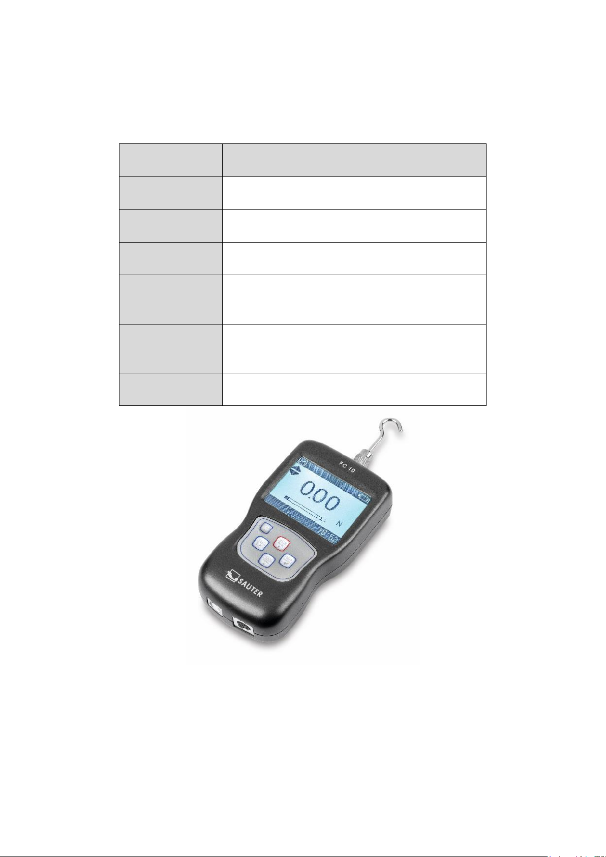
Manual Concrete tester
SAUTER Concrete tester
Version 1.0
07/2020
GB
PROFESSIONAL MEASURING
Page 2

2 FC 1K-BT-BA-e-2020
GB
SAUTER Concrete tester
V. 1.0 04/2020
Manual Concrete tester
Congratulations on the purchase of a digital concrete measuring device with internal
measuring cell from SAUTER. We hope you will enjoy your quality measuring device
with a wide range of functions. Please do not hesitate to contact us if you have any
questions, requests or suggestions.
Table of contents:
1 Introduction .................................................................................................... 4
2 Scope of delivery ........................................................................................... 4
3 The Shotcrete Tester ...................................................................................... 5
4
Using
the Tester ............................................................................................. 5
4.1 EN ISO 14488-2 ......................................................................................................................... 5
4.2 Principle Method A ................................................................................................................... 5
4.3
Test
protocol
form ..................................................................................................................... 5
4.4 Test specimen ........................................................................................................................... 6
4.5 Conversion curves ................................................................................................................... 6
5 Test Procedure ............................................................................................... 6
5.1 Prepare the tester ..................................................................................................................... 7
5.2 Test the concrete at ten sample locations ............................................................................. 7
6 Expression of Results ................................................................................... 7
6.1 Calculation of compressive strength ..................................................................................... 7
7 Technical data ................................................................................................ 8
7.1 Technical data FC with internal loadcell 1kN ........................................................................ 8
8 Display indication .......................................................................................... 9
9 Control buttons ............................................................................................ 10
10 Menu items ................................................................................................... 11
10.1 Language ................................................................................................................................. 11
10.2 Display modes ........................................................................................................................ 11
10.3 Storing measured values ....................................................................................................... 11
10.4 Delete all records .................................................................................................................... 11
10.5 Browse Menu .......................................................................................................................... 12
10.6 Print.......................................................................................................................................... 13
10.7 System settings ...................................................................................................................... 13
10.8 USB/Loading ........................................................................................................................... 14
10.9 Multifunctional port ................................................................................................................ 14
11 Warnings ...................................................................................................... 15
12 Adjustment FC ............................................................................................. 18
Page 3

FC 1K-BT-BA-e-2020 3
13 Technical drawings ...................................................................................... 19
14 Appendix 1 ................................................................................................... 34
14.1 Test protocol ........................................................................................................................... 34
14.2 Diagram sheet ......................................................................................................................... 34
Page 4

4 FC 1K-BT-BA-e-2020
1 Introduction
Please read these operating instructions carefully before commissioning, even if you
already have experience with SAUTER measuring instruments.
After receipt of the concrete tester, it should be checked in advance that no transport
damage has occurred, that the outer packaging, the plastic housing, other parts or
even the gauge itself have not been damaged. If any damage is evident, please
notify SAUTER GmbH immediately.
The FC can measure tensile and compressive forces very accurately and it is easy to
operate. In this special version it is suitable to measure the resistance of young
sprayed concrete. It can be held in the hand for measurements. It is although suitable
to cover the procedure according to the EN ISO 14488-2 (Method A) for subsequent
calculation of the compressive strength of concrete.
SAUTER offers optional software and accessories to make the measuring instrument
more versatile in use. Please ask SAUTER or the SAUTER supplier or visit our
website www.sauter.eu.
2 Scope of delivery
SAUTER FC, incl. internal battery
Transport case
Battery charger
15 Steel needles, 3mm with a taper angle of 60°
Needle holder
Needle holder adapter
Knurled nut
T-shaped measuring instrument holder
User Manual German and English
Page 5

FC 1K-BT-BA-e-2020 5
3 The Shotcrete Tester
SAUTER shotcrete tester supports you to measure accurate readings of the forces
required to penetrate sprayed or poured concrete during the initial strength
development stage of curing. With the force readings you are able to convert the force
values to a compressive strength value. The best use on-site to measure and testing
shotcrete according to BS EN ISO 14488 (Method A).
4
Using
the Tester
4.1 EN ISO 14488-2
This part specifies two methods from which an estimate of the in situ compressive
strength of young hardened sprayed concrete can be made. The strength development
of young sprayed concrete is assessed in the ranges of 0,2 MPa to 1,2 MPa and 3
MPa to 16 MPa respectively with Method A and Method B. The SAUTER Shotcrete
Tester gives you the possibility to test the force values and convert them according to
the EN ISO 14488-2 and gives you an overview of your sprayed concrete quality.
4.2 Principle Method A
This method is used to measure the force required to push a needle of specified
dimensions to penetrate into the sprayed concrete to a depth of 15 mm +/- 2 mm. A
penetrometer indicates the resisting force, through compression of a calibrated spring
from which an estimated compressive strength can be derived from a conversion
curve, to be provided by the producer of the test equipment The tester indicates the
resisting force, from which an estimated compressive strength can be derived by
means of the appropriate example conversion curve, included with the product and
shown in Appendix A.
4.3
Test
protocol
form
The resulting strength calculation from the test data requires the measurement of
compressive force at multiple sample points. A test protocol form (see Appendix 2
Example) is needed to record these data;
Project – construction site address
Date
Test equip Serial No.
Time
Place – of the measuring points
Measurement values
Page 6

6 FC 1K-BT-BA-e-2020
4.4 Test specimen
No special test specimen is required. The testing procedure can be used for
measurements at any location without advance preparation. A sprayed concrete layer
of no less than 100 mm thickness is required for testing.
4.5 Conversion curves
Appendix A of this user guide contains a graph of conversion curves to enable the
calculation of the equivalent compressive strength (MPa) of the concrete from a tester
force reading (N).
This graph is derived from the example calibration curves provided in EN 14488-2
Annex A (informative) of the test standard.
Two linear curves and their associated formulae are reproduced for two typical
aggregate mixes of <8 mm and <=16 mm respectively. The compressive strength value
on the y-axis may be derived from a resistance force reading on the x-axis either by
direct extraction from the curve, or calculation via the appropriate formula, as indicated.
These curves are provided as reference examples based on data published in the
standard, however the individual concrete rnix will affect the accuracy of the
approximation. The user is at liberty to irnplement their own correlation function if this
would be more appropriate.
5 Test Procedure
Record time and place of completion of spraying and start of testing.
Ensure the force indicator is set to zero.
Apply the device perpendicularly to the surface of the sprayed concrete layer
and steadily push in the needle to a depth of 15 mm in a single continuous
movement. If this is prevented, for instance because of a large aggregate
particle or reinforcement, then discontinue the test and repeat in an adjacent
location.
Choose the aggregate size 8 or 16 mm.
Read the resistance force from the scale, record the value on the protocol form
and return indicator to original position.
Clean the needle if necessary.
Repeat the test ten times as quickly as possible (and within 1 min for strengths
below 0,5 MPa) in an area representative of the sprayed region.
Record the time at which the testing is finished (on protocol form).
Page 7

FC 1K-BT-BA-e-2020 7
5.1 Prepare the tester
Check the fit of the measuring tip
If it is worn out, please replace it
Switch on the FC.
Go to Menu choose Measurment an change Unit to “N” if it’s not already there.
Go to Test Menu and switch to Peak.
Go Back to Measurement screen
Perform your measurement.
5.2 Test the concrete at ten sample locations
Prepare the sample data row
To calculate the single representative value for the compressive strength of the
shotcrete at each test instance, 10 individual samples are taken with the tester.
The data are entered into a row on the test protocol form against the timestamp, for
example at 5, 20, 40, 60,120 minutes.
6 Expression of Results
6.1 Calculation of compressive strength
If you use the Excel file (www.kern-sohn.com), it will be calculate the values by itself
and mark the points in the diagram sheet. So you will get a proper clean protocol of
documentation of the quality of your sprayed concrete.
Page 8
8 FC 1K-BT-BA-e-2020
7 Technical data
7.1 Technical data FC with internal loadcell 1kN
Measuring
device
FC 1K
Capacity
1000N
Measurement
uncertainty
±0.3% of Max (measuring range)
Relative air
humidity
15% to 80% Humidity
Weight
(without
accessories)
Approx. 500g
Dimensions
Display unit
(LxWxH)
140x71x36mm
Thread
M6
Page 9
FC 1K-BT-BA-e-2020 9
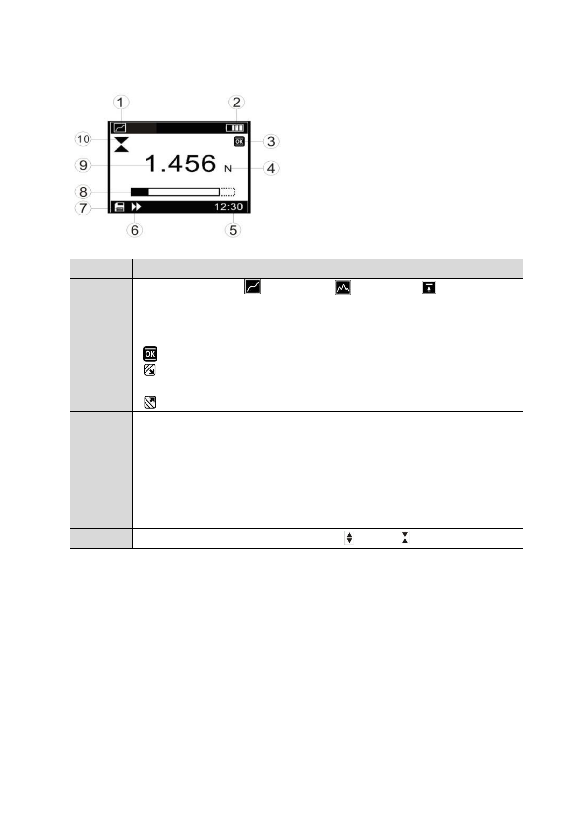
8 Display indication
Position
Description
1
Measuring mode: Track mode; Peak mode; Preset mode
2
Battery symbol: shows the current charge status; flashes when the
battery needs to be recharged
3
Default value status:
: the value is between the lower and upper limit and is OK
: the value is between the lower limit value and the value of 75% of
the lower limit value, i.e. the value falls below the lower limit value
: the value exceeds the upper limit value
4
Measuring units: the selected unit is displayed (N, kgf, ozf or lbf optional)
5
System Clock
6
Data transmission symbol
7
Data memory icon
8
Analogue load bar display
9
Current measured value
10
Direction of force (tension ( ) Pressure ( )
Page 10

10 FC 1K-BT-BA-e-2020
9 Control buttons
SAVE/ESC:
Saving the measured value
By pressing the SAVE/ESC button in the menu, you can return to the previous
page
ZERO (zeroing):
Zeroing the display
Arrow 'up' in the menu
ENTER:
Opening the menu
Confirm the selection in the menu
Mode (mode change):
Selecting the measuring mode
Arrow key 'down' in the menu
ON / OFF:
On / Off button (press button for approx. 1 s)
Page 11

FC 1K-BT-BA-e-2020 11
10 Menu items
10.1 Language
The display of the force gauge has several menu language versions. Select the desired
language setting.
10.2 Display modes
The force gauge has two display modes: force transducer oriented display and reverse
display. Select the desired display mode as required.
10.3 Storing measured values
The force gauge is equipped with the function for storing measured values. The stored
data can be searched or printed out.
During the measurement, press the key to save the respective value. The display
will show the data storage symbol ( ).
The stored data is displayed. In Track mode and Preset mode, the current force value
is measured, and in Peak mode, the maximum value.
10.4 Delete all records
To empty the memory, all data can be deleted at once. The display then shows a dialog
box with a corresponding security prompt.
Individual data can be deleted from the 'Browse' menu.
Page 12

12 FC 1K-BT-BA-e-2020
10.5 Browse Menu
With the menu 'Browse' you can browse the memory contents of the save order.
The keys or are used to navigate between the data records .
At the top of the list the last saved record is displayed.
After pressing the button, a small selection window appears on the display. In this
window you can choose between the 'Delete' or 'Print' option
If the 'Delete' option is selected, a dialog box with a corresponding security prompt is
displayed.
To exit the menu, press the key.
If the percentage drop is between 5% - 10%, please contact the supplier to have the
loadcell replaced. These values are given as a guide only. The actual need for
calibration/replacement of the loadcell varies with its individual characteristics.
Page 13

FC 1K-BT-BA-e-2020 13
10.6 Print
With the mini-printer the stored data can be printed out.
To do this, select the menu 'Print' and then the function 'Selected' or 'All'.
If the 'Selected' option is selected, the pressure range must be determined. If you
choose the 'All' option, a dialog box appears with a confirmation prompt
10.7 System settings
In the 'System' menu, settings for the display, automatic switch-off function, backlight,
key tone, etc. can be selected.
→
→
Fig 3-8
Page 14

14 FC 1K-BT-BA-e-2020
10.8 USB/Loading
Via this port, USB2.0 can be used to connect the force gauge to a PC computer for
data processing.
The Ni-MH battery can also be charged via this connection. To do this, connect the
mains adapter.
10.9 Multifunctional port
The PIN assignment is shown in the table.
Pin
Description
1
TX (RS232)
2
RX (RS232)
3
GND (RS232)
4
Default value output B
5 6
Default value output C (general)
7
Default value output A
8
10.9.1 RS-232
The RS232 interface is only used to connect a mini-printer to print out the data
received.
RS-232 specification:
- Hardware flow control: none
- Word length: 8 bits
- Stop bit: 1 bit
- Parity: none
- Data transmission rate: 38400
Fig 4-1
Page 15

FC 1K-BT-BA-e-2020 15
10.9.2 Default value outputs
Two preset value outputs form an open collector in the NPN version.
The circuit diagram below shows the inner default value circuit:
Pins 6 and 7 are switched on after the overload alarm is triggered.
In setting mode, pins 6 and 7 are switched on after the upper limit value has been
exceeded, and pins 4 to 6 - after the lower limit value has been fallen below.
Max. permissible voltage: for pins 7 to 6 and 4 to 6 the voltage must be below
35V, and for pins 6 to 7, pins 6 to 4 below 6V!
11 Warnings
Incorrectly performed force measurements can lead to serious injury to persons and
damage to objects and must therefore only be performed by trained and experienced
personnel.
In particular, it must be avoided that forces act on the purchased measuring
instrument which exceed the maximum load (Max) of the instrument or which do not
act axially via the external and internal load cell; or if high impulse forces act on the
measuring instrument.
Avoid twisting the loadcell, otherwise it could be damaged and the measuring
accuracy will decrease in any case.
Inappropriate use
Do not use the measuring instrument for medical weighing.
If small quantities of the material to be measured are removed or added, incorrect
measurement results may be displayed due to the "stability compensation" in the
measuring instrument! (Example: Slow flow of liquids out of a container suspended
from the measuring cell).
Page 16

16 FC 1K-BT-BA-e-2020
Do not apply a continuous load to measuring instruments with external measuring
cell.
Overloads
Please prevent the measuring instrument from being overloaded beyond the
specified maximum load (Max), minus any tare load that may already be present.
This can damage the measuring instrument (danger of breakage!)
Attention:
Make sure that never let people or objects
are under the load, as this could injure
or could be damaged!
The measuring instrument is not suitable for weighing people, do not use it as an
infant measuring instrument!
The measuring device does not comply with the German Medical Devices Act
(MPG).
Never operate the measuring instrument in rooms where there is a risk of
explosion. The standard version is not explosion-proof.
The design of the measuring instrument must not be changed. This can lead to
incorrect measurement results, safety-related defects and the destruction of the
measuring device.
The measuring instrument may only be operated or maintained by trained
personnel.
The measuring instrument may only be used in accordance with the described
specifications.
SAUTER must give written approval for any other areas of use / applications.
Warranty
The warranty is void if
Non-compliance with our guidelines of the operating instructions
Use outside the described field of application
Modifying or opening the device
mechanical damage and damage caused by agents such as liquids or liquids
have been caused
improper assembly or electrical installation
Overloading the measuring cell
Test equipment monitoring
As part of quality assurance, the metrological characteristics of the measuring
instrument and any test weight that may be present must be checked at regular
intervals. The user responsible must define a suitable interval for this purpose as well
as the type and scope of this inspection.
Page 17

FC 1K-BT-BA-e-2020 17
Information on the monitoring of measuring instruments and the necessary test
weights is available on the SAUTER homepage (www.sauter.eu). The weights and
measuring instruments can be checked and adjusted quickly and at favourable prices
in KERN's accredited DAkkS laboratory (traceability to the national standard).
Note:
To view the CE declaration, please click on the following link:
https://www.kern-sohn.com/shop/de/DOWNLOADS/
Page 18

18 FC 1K-BT-BA-e-2020
12 Adjustment FC
After a certain period of use, the force gauge may show deviations in a measuring
range which are due to the functioning of the device or other external influences.
In such a case, the device can be sent to our customer service for expert testing and
recalibration.
However, if you have standard force gauges and a measuring stand, you can perform
the calibration yourself according to the instructions below:
1. Fasten the force gauge to the measuring stand or to another holder
2. Zero the tare value by pressing the key.
3. Call up the calibration menu.
4. Load with test weight. The current measured value now equals the test weight
load. Wait until the measured value stabilizes before reading the measured
value.
5. Use the and keys to enter the test weight.
6. Press the key to initiate a new calibration procedure. The calibration process
can be interrupted by pressing the key.
If the calibration procedure is completed or interrupted three times, a message
window appears with the request to confirm the displayed message "Save and
Exit" (YES) or (NO).
Press the or key to select the desired option, then press the key .
If the "YES" option is selected, the display shows "Calibration complete!
❶Kalibrierungsdauer
❷Aktueller Measured value
❸Standardwert, entered
Page 19

FC 1K-BT-BA-e-2020 19
13 Technical drawings
Hole 4-M4P0.7
max. width 8
Unit
mm
Page 20

20 FC 1K-BT-BA-e-2020
14 Technical data
14.1 Technical data FL with internal loadcell up to 1kN
Measuring
device
FL 5
FL 10
FL 20
FL 50
FL 100
FL 200
FL 500
FL 1K
Capacity
5N
10N
20N
50N
100N
200N
500N
1000N
Measurement
uncertainty
±0.2% of Max (measuring range)
Work
temperature
15°C to 35°C
Relative air
humidity
15% to 80% Humidity
Weight
(without
accessories)
Approx. 500g
Dimensions
Display unit
(LxWxH)
160x75x30mm
Thread
M6
Page 21

FC 1K-BT-BA-e-2020 21
674
2 3 5 8 1
15 Battery indicator / power supply
Battery level > 4.8 V
4.8 V > Battery level > 4.7 V
4.7 V > Battery level > 4.4 V
4.4 V > Battery level > 4.0 V
Battery level < 4.0 V
If the battery voltage is less than 3.9V, a message appears that the battery
is exhausted and the device switches off automatically
The FL is equipped with four Nickel Metal Hybrid (NiMH) batteries type AAA. For
safety reasons during transport, the batteries are supplied uncharged. For maximum
battery life, we recommend that you charge the batteries only with the original
charger (supplied) for a period of 14-16 hours before using the meter for the first
time.
16 Display indication
Position
Description
1
Measurement result
2
Display mode (track, peak (pull), peak (push)
3
Display of the direction of force
4
battery charge indicator
5
Number of occupied memory locations
6
Activated pass-fail criterion
7
Display unit of the measurement result
8
Progress bar
Page 22

22 FC 1K-BT-BA-e-2020
17 Control buttons
MENU/ESC:
Opens the menu window with the individual submenus
By pressing the MENU/ESC button in the menu, you can return to the previous
page
ZERO (zeroing):
Zeroing the display in track mode (tare function)
ENTER:
Confirm the selection in the menu
Saving a measured value in PEAK mode
PRINT (print function):
Output of the memory contents to PC or printer
RESET (delete function):
Delete the current PEAK value
UNIT (units of measurement):
Press the key briefly: Switch between N, gf, kgf, ozf, lbf, mN
Mode (mode change):
Assignment with three functions:
Track mode (continuous measurement)
Peak Mode Train
Peak Mode Print
ON / OFF:
On / Off button (press button for approx. 1 s)
Page 23

FC 1K-BT-BA-e-2020 23
18 Functions
18.1 Limit value display Good / Bad
LED display for good / bad tests
Colour
Function
Red
Exceeding the upper limit value
Green
Indicates that the pass-fail criterion has been
reached
Yellow
Falling below the lower limit value
An upper and a lower limit value can be programmed. The measuring instrument
compares the measurement result with the limit values and outputs the result as a
signal in red or green light diodes.
Setting of the limit values see MENU PASS-FAIL
With the left arrow key the cursor is moved to the desired value. With the UP or
DOWN key the value can be changed. By pressing and holding one of these keys,
scrolling is possible. With the right arrow key the unit can be changed. With the
ENTER-key the settings are saved and you return to the main menu.
The display now shows a "PF".
The PASS-FAIL option is automatically disabled if the upper and lower limits are set
to 0 Newton. The lower value must also always be smaller than the upper one.
18.2 Invert display
The display can be rotated by 180°. To do this, do the following:
When the power is off, press and hold the "MENU/ESC" key. In addition, the "On/Off"
key is pressed and the unit switches on, thus rotating the display.
18.3 Store measured value in memory
Any measured value can be stored in the memory at any time by pressing the
ENTER key. A maximum of 500 readings can be stored.
Page 24

24 FC 1K-BT-BA-e-2020
18.4 Memory / Storage
The memory is used to view the stored data. It can store 500 readings. Currently,
individual entries or all entries can be deleted, or the measurement data of the
memory can be printed out.
To enter the MEMORY menu, the MENU/ESC button must be pressed. Use the UP
or DOWN button to move the cursor to MEMORY. Then confirm with the ENTER
button and you are on the memory page. Press the ESC button to return to the main
menu page.
With the arrow keys UP and DOWN the page can be changed within the memory and
by pressing and holding one of these two keys it is possible to scroll up or down.
By pressing the PRINT key, the memory contents can be printed out via the serial
port.
By pressing the ZERO button, the DELETE menu is accessed
Use the UP and DOWN arrow keys to select the desired delete option. If NO is
selected here and confirmed with the ENTER key, the meter returns to the memory
page.
When DELETE is selected and the ENTER button is pressed to confirm, the currently
stored measurement is deleted and the instrument returns to the memory page.
When DELETE ALL is selected and the ENTER button is pressed to confirm, all
stored measurements are deleted and the instrument returns to the memory page.
Page 25

FC 1K-BT-BA-e-2020 25
18.5 Diagnostics
This function is used to check the loadcell. If it is suspected that the loadcell has
been overloaded, the status can be determined immediately.
To do this, place the device in a horizontal position on a flat surface and call up the
main menu page. To enter the DIAGNOSTIC menu, the MENU/ESC button must be
pressed. Use the UP or DOWN button to move the cursor to DIAGNOSTIC and
confirm with the ENTER button. You are now on the DIAGNOSTIC page.
Press the ESC key to return to the main menu page.
If the percentage drop is between 5% - 10%, please contact the supplier to have the
loadcell replaced. These values are given as a guide only. The actual need for
calibration/replacement of the loadcell varies with its individual characteristics.
18.6 Select Output
With this option the used data output, RS 232 or USB is selected.
There is an analog output on the device. This generates a signal that goes from +2V
to -2V. This signal is a percentage of the maximum value of the force gauge. FOR
EXAMPLE..: FL100 50N is measured in the direction of pull, then a -1V signal is
applied to the analog output. 75N in compression direction, then + 1.5V is present at
the analog output. If the instrument is in PASS - Fail mode, 2V for PASS and 0V for
FAIL are present at the analog output.
Page 26

26 FC 1K-BT-BA-e-2020
19 Computer control of the force gauge
With the RS 232 interface a connection from the force gauge to the PC can be
established by sending RS232 commands.
RS232 command
Action
m
Change measuring mode
u
Change measuring unit
z
Set device to "zero
r
Perform reset on the device
20 RS232 output signal
The reading of the FL shown on the display can be transferred to the PC by pressing
the PRINT button or by issuing a command instruction to the force gauge from the
PC.
RS232
command
Action
l
Send the direct reading with unit
p
Send peak value (on pull) with unit
c
Send peak value (on pressure) with unit
x or pressing
PRINT KEY
- Send the direct reading with unit if the current mode is
the track mode
- Send peak value (on pull) with unit if the current mode
is peak mode
- Send peak value (on pressure) with unit if the current
mode is the peak value print mode
d
Send save
!
Send information about the device such as model,
capacity, serial number, firmware check, original offset,
current offset, overload counter
Page 27

FC 1K-BT-BA-e-2020 27
20.1 Interface protocol
RS-232 Parameters
- Baud rate: 9600
- Data bit: 8
- Parity: none
- Stop bit: 1
- Start bit 1
The measured value is requested by the ASCII character "9".
The returned measured value looks like this:
e.g. 0011.70 means -11.70 Newton if Newton is set
|_______ > first character describes the sign (0 = minus = pressure; 1 =
plus = pull)
| |____>-------- the remaining 6 digits describe the measured value as ASCII
character string
or: 1021.15 means +21.15 N (tractive force)
20.2 Assignment of the RS232 data interface
Pin
Signal
Illustration
2
TxD
Data output
3
GND
Ground
6
RxD
Input for control signal
Page 28

28 FC 1K-BT-BA-e-2020
21 Warnings
Incorrectly performed force measurements can lead to serious injury to persons and
damage to objects and must therefore only be performed by trained and experienced
personnel.
In particular, it must be avoided that forces act on the purchased measuring
instrument which exceed the maximum load (Max) of the instrument or which do not
act axially via the external and internal load cell; or if high impulse forces act on the
measuring instrument.
Avoid twisting the loadcell, otherwise it could be damaged and the measuring
accuracy will decrease in any case.
Inappropriate use
Do not use the measuring instrument for medical weighing.
If small quantities of the material to be measured are removed or added, incorrect
measurement results may be displayed due to the "stability compensation" in the
measuring instrument! (Example: Slow flow of liquids out of a container suspended
from the measuring cell).
Do not apply a continuous load to measuring instruments with external measuring
cell.
Overloads
Please prevent the measuring instrument from being overloaded beyond the
specified maximum load (Max), minus any tare load that may already be present.
This can damage the measuring instrument (danger of breakage!)
Page 29

FC 1K-BT-BA-e-2020 29
Attention:
Make sure that never let people or objects
are under the load, as it injures
or could be damaged!
The measuring instrument is not suitable for weighing people, do not use it as an
infant measuring instrument!
The measuring device does not comply with the German Medical Devices Act
(MPG).
Never operate the measuring instrument in rooms where there is a risk of
explosion. The standard version is not explosion-proof.
The design of the measuring instrument must not be changed. This can lead to
incorrect measurement results, safety-related defects and the destruction of the
measuring device.
The measuring instrument may only be operated or maintained by trained
personnel.
The measuring instrument may only be used in accordance with the described
specifications.
SAUTER must give written approval for any other areas of use / applications.
Warranty
The warranty is void if
Non-compliance with our guidelines of the operating instructions
Use outside the described field of application
Modifying or opening the device
mechanical damage and damage caused by agents such as liquids or liquids
have been caused
improper assembly or electrical installation
Overloading the measuring cell
Test equipment monitoring
As part of quality assurance, the metrological characteristics of the measuring
instrument and any test weight that may be present must be checked at regular
intervals. The user responsible must define a suitable interval for this purpose as well
as the type and scope of this inspection.
Information on the monitoring of measuring instruments and the necessary test
weights is available on the SAUTER homepage (www.sauter.eu). The weights and
measuring instruments can be checked and adjusted quickly and at favourable prices
in KERN's accredited DAkkS laboratory (traceability to the national standard).
Note:
To view the CE declaration, please click on the following link:
https://www.kern-sohn.com/shop/de/DOWNLOADS/
Page 30

30 FC 1K-BT-BA-e-2020
22 Adjustment instruction FL
Introduction:
This manual describes the adjustment procedure, although some programming
modes are password protected.
Important! During the adjustment procedure, all weights for loading the sensor should
be calibrated.
Tempering:
Before the measuring instrument is handed over to the calibration laboratory, the
respective instrument must be checked for possible damage and the order
specification.
Before starting adjustment, allow the measuring instrument to reach the working
temperature of the calibration laboratory for at least 2 hours.
Preparation:
Insert a full set of charged batteries in the battery compartment or connect a standard
power supply
Calibration:
1. Switch on the measuring instrument
2. Select the main menu by pressing the MENU key and select the menu function
CALIBRATION with the cursor keys UP and DOWN. Then press the ENTER key.
The ENTER PASSWORD window will appear on the screen.
ENTER PASSWORD [Enter password].
4 FIGURES
PASSWORD: 0000*
* Master password = 7780
Use the UP and DOWN arrow keys to scroll up and down. The left and right arrows
can be used to select the left and right positions. To change a digit, press and hold
for a moment.
Press the ENTER key to confirm the password. If the password is correct, the display
shows the calibration menu window.
Page 31

FC 1K-BT-BA-e-2020 31
CALIBRATION MENU
1) MAXIMUM LOAD
2) VOLTAGE INCREASE
3) COMPRESSION GAIN
4) SET NEW PASSWORD
3. Select the correct value of the weight for the respective measuring instrument. To
set the load, use the UP and DOWN arrow keys to select the MAX CAPACITY
menu function and press ENTER. The menu window for setting the maximum
load appears on the screen.
SETTING MAX. LOAD 1/2
SETTING MAX. LOAD 2/2
4. Use the UP and DOWN arrow keys to select the maximum load, press the
selected value and hold for a moment.
Press the ENTER key to save the selected value. Then return to the calibration
menu.
Page 32

32 FC 1K-BT-BA-e-2020
5. To calibrate in the voltage direction: use the UP and DOWN arrow keys to select
TENSION GAIN in the calibration menu and then press ENTER. The display
shows a menu window for voltage increase.
5.1. Zero voltage
Set up the measuring device together with the necessary accessories for
performing the voltage calibration
apply a force of 100% of the meter's power to the weight
Remove the load, leave the device standing
as soon as the display becomes stable, press the ZERO key to save the zero
display
5.2. maximum stress
apply the voltage force of 100% of the meter power
Calibrate the voltage increase with the UP and DOWN arrow keys and RIGHT
and LEFT until the meter displays the maximum voltage result
touch the ENTER key to save the results for the entire voltage scale.
6. Compression calibration: In the calibration menu, use the UP and DOWN arrow
keys to select the COMPRESSION GAIN menu function and then press ENTER.
The display will show a menu window for compression gain.
Page 33

FC 1K-BT-BA-e-2020 33
6.1. Zero Compression
Set up the measuring device and all necessary accessories for performing the
compression calibration
apply a force of 100% of the meter's power to the weight
Remove the load, leave the device standing
as soon as the display becomes stable, press the ZERO key to save the zero
display
6.2. maximum compression
apply the compression force of 100% of the gauge power
Calibrate the compression gain with the UP and DOWN arrow keys and
RIGHT and LEFT until the meter displays the maximum compression result
touch the ENTER key to save the results for the entire compression scale
7. After successful calibration, remove all accessories from the meter and place the
meter on a flat surface with its backside facing up.
Select the voltage increase menu window, press the ZERO key to obtain the
primary calibration offset, date and time and reset the overload counter.
Page 34

34 FC 1K-BT-BA-e-2020
23 Appendix 1
23.1 Test protocol
23.2 Diagram sheet
 Loading...