

Page 1
KERN & Sohn GmbH
Ziegelei 1
E-Mail: info@kern-sohn.com
Phone: +49-[0]7433- 9933-0
Internet: www.kern-sohn.com
Installation Instructions
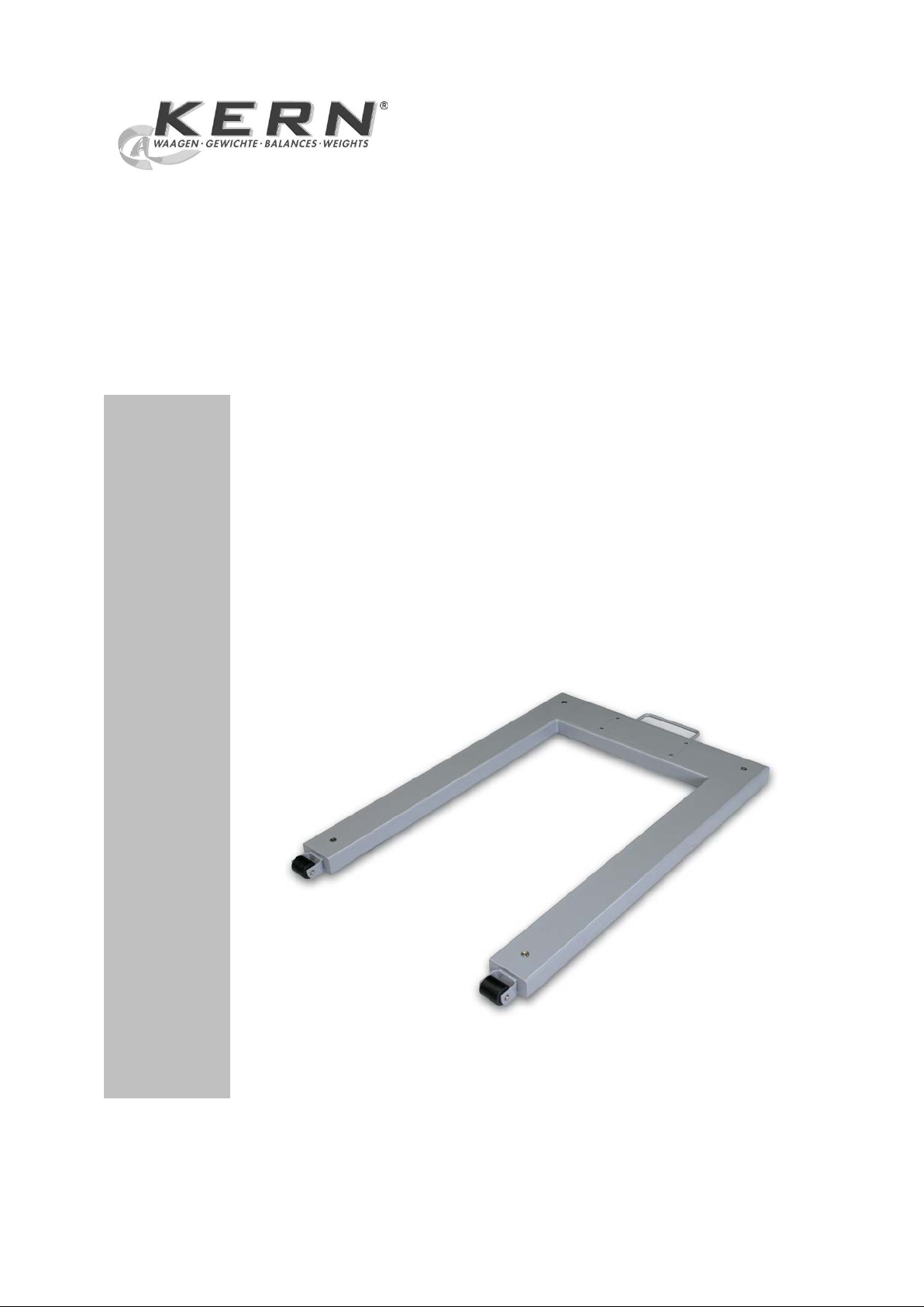
U-shaped weighing bridge
KERN KFU
Version 1.1
05/2012
GB
D-72336 Balingen
Fax: +49-[0]7433-9933-149
KFU-IA-e-1211
Page 2
GB
KERN KFU
U-shaped Weighing bridge
Version 1.1 05/2012
Installation instructions
Contents
1. Technical data ................................................................................................ 3
2 Appliance overview ....................................................................................... 4
3 Basic Information (Gen eral) .......................................................................... 5
3.1 Documentation ......................................................................................................................... 5
3.2 Proper use ................................................................................................................................. 5
3.3 Improper Use ............................................................................................................................ 5
3.4 Warranty .................................................................................................................................... 5
3.5 Monitoring of Test Resources ................................................................................................. 6
4 Basic Safety Precauti o ns .............................................................................. 6
4.1 Pay attention to the instructions in the Operation Manual .................................................. 6
4.2 Personnel training .................................................................................................................... 6
5 Transport and storage ................................................................................... 6
5.1 Testing upon acceptance ........................................................................................................ 6
5.2 Packaging / return transport ................................................................................................... 6
6 Unpacking, Setup and Commissioning ....................................................... 7
6.1 Installation Site, Location of Use ............................................................................................ 7
6.2 Unpacking and placement ....................................................................................................... 8
7 Operation ........................................................................................................ 9
7.1 Operation limits ........................................................................................................................ 9
7.2 Load/unload the weighing syste m ........................................................................................ 10
8 Service, maintenance, disposal .................................................................. 11
8.1 Daily checks ............................................................................................................................ 11
8.2 Cleaning .................................................................................................................................. 11
8.3 Service, maintenance ............................................................................................................. 11
8.4 Disposal ................................................................................................................................... 11
8.5 Instant help ............................................................................................................................. 12
9 Service documentation ............................................................................... 13
9.1 Overview, setting specification, tolerances ........................................................................ 13
9.2 Checking and adjustment of the corner load ...................................................................... 14
10 Preload / Deadload settings ........................................................................ 16
2 KFU-IA-e-1211
Page 3
1. Technical data
Max
d
e
Min
approx.
approx.
kg g g
kg
kg m kg
Model
KFU 600V20M
KFU 1500V20M
KFU 600V30M
KFU 1500V30M
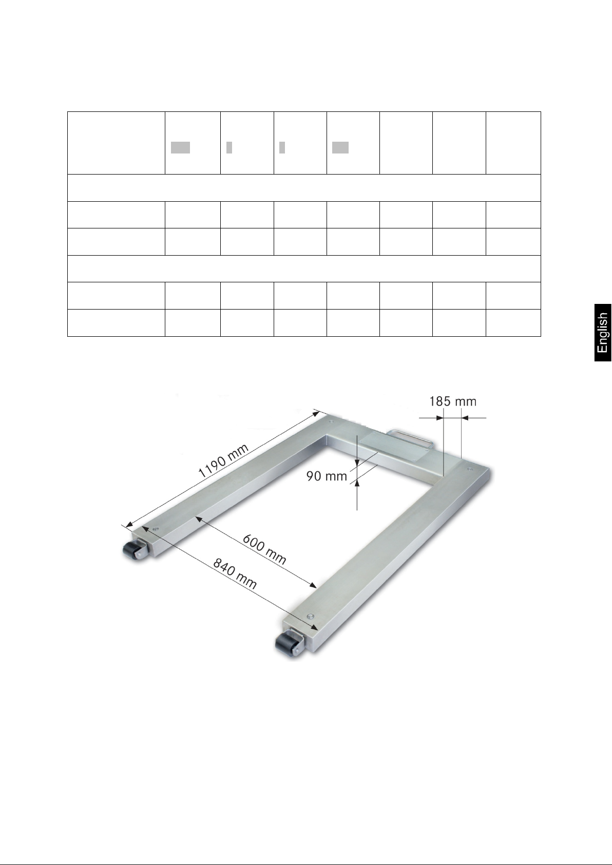
Dimensions:
Weighing
range
Readability
Verification value
Minimum
load
Preload
additive
Cable
length
Net
weight
Painted steel
600 200 200 4 120 5 41
1500 500 500 10 300 5 41
Stainlees steel
600 200 200 4 120 5 42
1500 500 500 10 300 5 42
KFU-IA-e-1211 3
Page 4
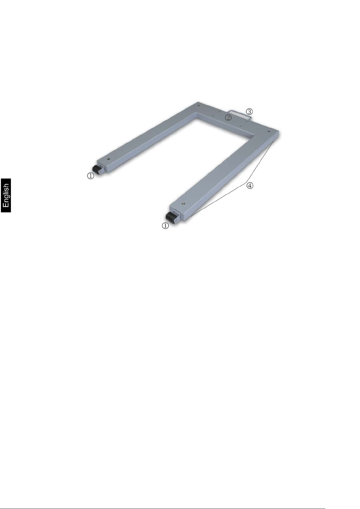
2 Appliance overview
There are two versions of the U-weighing bridge, painted steel ( _V20) and stainless
steel ( _V30).
Rollers for comfortable transport
Covering connection b ox
Holding grip for comfortable transport
Oscillating weighing cell feet and weighing cells
4 KFU-IA-e-1211
Page 5

3 Basic Information (General)
3.1 Documentation
This installation instructions contain all data about placement and commissioning of
the U-weighing bridges KERN KFU.
In combination with a display unit, in the following named weighing system, operation
and configuration can be seen in the manual of the display unit.
3.2 Proper use
The KERN KFU is designed for weighing Euro-pallets and containers with the
dimensions of Euro-pallets. It is provided for use as „non-au to mati c b al ance“ . As
soon as a stable weighing value is reached the weighing value can be read.
3.3 Improper Use
Do not leave permanent load on the weighing plate. This may damage the measuring
system.
-Impacts and overloading exceeding the stated maximum load (max) of the weighing
system, minus a possibly existing tare load, must be strictly avoided. This could
damage the weighing system.
Never operate the unit in explosive environment. The serial version is not explosion
protected.
Changes to the weighing system’s design are not permitted. This may lead to
incorrect weighing results, safety-related faults and destruction of the weighing
system.
The weighing system may only be operated in accordance with the described default
settings. Other areas of use must be released by KERN in writing.
3.4 Warranty
Warranty claims shall be voided in case
• Our conditions in the operation manual are ignored
• The appliance is used outside the described uses
• Structural changes of the unit
• Mechanical damage and damage caused by media, liquids
• Natural wear and tear
• The appliance is improperly set up or incorrectly electrically connected
• Overloading of the measuring sy stem
KFU-IA-e-1211 5
Page 6

3.5 Monitoring of Test Resources
Carefully read this operation manual before setup and commissioning,
even if you are already familiar with KERN balances.
In the framework of quality assurance the measuring-related properties of the
weighing system and, if applicable, the testing weight, must be checked regularly.
The responsible user must define a suitable interval as well as type and scope of this
test. Information is available on KERN’s home page (www.kern-sohn.com with regard
to the monitoring of balance test substances and the test weights required for the
weighing system. In KERN's accredited DKD calibration laboratory test weights and
weighing systems may be calibrated (return to the national standard) fast and at
moderate cost.
4 Basic Safety Precautions
4.1 Pay attention to the instructions in the Operation Manual
4.2 Personnel training
The appliance may only be operated and maintained by trained personnel.
The installation of the display unit is restricted to specialist staff possessing well
acquainted knowledge with the workings of weighing scales.
5 T ransport and storage
5.1 Testing upon acceptance
When receiving the appliance, please check packaging immediately, and the
appliance itself when unpacking for possibl e v i si bl e damage.
5.2 Packaging / return transport
Keep all parts of the original packaging for a possibly
required return.
Only use original packaging for returning.
Prior to dispatch disconnect all cables and remove
loose/mobile parts.
Reattach possibly supplied transport securing devices.
Secure all parts against slipping and damage.
6 KFU-IA-e-1211
Page 7

6 Unpacking, Setup and Commi s si oning
6.1 Installation Site, Location of Use
The U-weighing bridges are designed in a way that reliable weighing results are
achieved in common conditions of use.
You will work accurately and fast, if you select the right location for your weighing
system.
Therefore, observe the following for the installation site:
• Place the weighing system on a firm, level surface;
The foundation at the installation site must be able to carry the weight of the
weighing system as well as the weight of the maximum load.
• Avoid extreme heat as well as temperature fluctuation caused by installing
next to a radiator or in the direct sunlight;
• Protect the weighing system against direct draughts due to open windows and
doors;
• Avoid jarring during weighing
• Protect the weighing system against high humidity, vapours and dust;
• Do not expose the device to extreme dampness for longer periods of time.
Non-permitted condensation (co ndensation of air humidity on the appl i ance)
may occur if a cold appliance is taken to a considerably warmer environment.
In this case, acclimatize the disconnected appliance for ca. 2 hours at room
temperature.
• Avoid static charge of goods to be weighed or weighing container.
• Do not lean the weighing system against the wall.
• Do not move the weighing system when it is loaded.
• Keep away chemical substances such as liquids or gases which may attack or
damage the weighing system inside or outside.
• Keep the IP-protection of the unit
Major display deviations (incorrect weighing results) may be experienced should
electromagnetic fi elds ( e.g . due to mobile phones or radio equipment), static
electricity accumulations or instable power supply occur. Change location or remove
source of interference.
KFU-IA-e-1211 7
Page 8

6.2 Unpacking and placement
Danger for the back!
Position adjustment screw of the weighing cell
feet
Position of weighing cell
The weighing system is quite heavy. Always use an
CAUTION
Unpacking:
Remove the outer packaging.
Lift the weighing system off the packaging material, see note of caution.
Secure the weighing system that it cannot fall down when it is lifted.
Make sure that the contents of the packaging is complete.
Scope of delivery:
• U-weighing bridge with assembled connection cable
• 4 weighing cell feet
• Instruction Manual
Placing:
Make sure that the surface of the placement site, especially around the weighing cell
feet, is even. Small unevenness can be offset by adjustment of the weighing cell feet.
Before a final placement install the four weighing cell feet. For transporting lift-off
the handle and move it on the conveyor rollers.
Settle down the weighing system and check if it is positioned evenly and all the
four feet touch the floor. Remove the covering screw and carry out adjustment if
necessary by turning the adjustment screw on the four weighing cells.
according lifting device to lift it out of the packaging or
to transport it to the required placement site
Make sure that during lifting and settling the connection cable is not squeezed or
damaged.
8 KFU-IA-e-1211
Page 9

7 Operation
Information about
• Mains connection
Mains is connected via the connection cable of the display unit.
• Initial Commissioning
• Connection of peripheral devices
• Adjustment, linearization and verification
Only the complete balance can be verified, that means the U-weighing bridge
in connection with an appropriate display unit.
You will find the accurate operation in the operating instructions which are included in
the scope of delivery.
7.1 Operation limits
The U-weighing bridge is designed for an even distributed load.
KFU-IA-e-1211 9
Page 10

• Avoid falling load, shock loads and impacts from the side.
• The forks of the fork lift truck may not touch the pallet or the balance during
weighing process.
• Do not move the balance at any moment, when it is loaded.
7.2 Load/unload the weighing system
Place the load on the scales using a pallet lifting truck, a crane or a forklift truck.
Ensure that the load is not swinging when it is placed onto the scales.
Lift the load first vertically at least 10 cm above the scales before it is removed or
newly placed.
10 KFU-IA-e-1211
Page 11

8 Service, maintenance, disposal
Before any maintenance, cleaning and repair works, separate the
device from mains voltage.
8.1 Daily checks
Ensure that all the four feet touch the floor.
Ensure that the connection cable to the display unit and the mains connecti on
cable of the display unit are not damaged.
Make sure that the balance is free of dirt, especially under the edges of the
balance.
8.2 Cleaning
! Remove regularly corrosive substances.
! Keep IP protection.
! Do not point a water or steam jet onto the weighing cells.
U-weighing bridge, painted steel
Clean the weighing system with a soft cloth soaked in mild cleaning agent.
Ensure that no liquid penetrates into the device. Rub with a dry clean cloth.
U-Weighing bridge, stainless steel
Clean the stainless steel parts with a soft cloth soaked in cleaning agent
appropriate for stainless steel.
For stainless steel sheet do not use cleaning agents which contain sodium
hydroxide, acetic acid, hydrochloric acid, sulphuric acid or citric acid.
Do not use metallic brushes or cleaning sponges of steel wool as this will cause
superficial corrosion.
8.3 Service, maintenance
The appliance may only be opened by trained service technicians who are
authorized by KERN.
Make sure that the weighing system is calibrated regularly, see chap. Testing
instruments control.
8.4 Disposal
Disposal of packaging and appliance must be carried out by operator according
to valid national or regional law of the location where the appliance is used.
KFU-IA-e-1211 11
Page 12

8.5 Instant help
In case of an error in the program process, briefly turn off the balance and disconnect
from power supply. The weighing process must then be restarted from the beginning.
Help:
Fault Possible cause
The displayed weight is permanently
changing
The weighing result is obviously
incorrect
Should other error messages occur, switch balance off and then on again. If the error
message remains inform manufacturer.
• Draught/air movement
• Sites with vibration.
• Weighing plate has contact with other
objects.
• Electromagnetic fi elds / stati c c har g i ng
(choose different location/switch off
interfering device if possible)
• No zero display when balance unloaded
• Adjustment is no longer correct.
• Great fluctuations in temperature.
• The balance is on an uneven surface.
• Electromagnetic fi elds / stati c c har g i ng
(choose different location/switch off
interfering device if possible)
12 KFU-IA-e-1211
Page 13

9 Service documentation
• This chapter is only provided for a specialist of balances !
-1
-0,75
-0,5
-0,25
0
0,25
0,5
0,75
1
0 500 1000 1500
[kg]
[g]
-0,4
-0,3
-0,2
-0,1
0
0,1
0,2
0,3
0,4
0 100 200 300 400 500 600
[kg]
[g]
600 kg
1500 kg
• The weighing bridges are carried out in DMS sensor technology, at
9.1 Overview, setting specification, tolerances
every corner there is a DMS weighing cell.
• The analogue-digital conversion takes place in the display unit. There
are also saved all balance and country specific data.
Test and setting specification:
Capacity 600 kg
Readability 200 g
Min 4 kg
Max 600 kg
1/3 corner load 200 kg
Tolerance 200 g
1500 kg
500 g
10 kg
1500 kg
500 kg
500 g
Verification data and tolerances acc. to OIML:
KFU-IA-e-1211 13
Page 14

9.2 Checking and adjustment of the corner load
Checking the corner load
Adjusting the corner load
For a better control of the changes which are resulting
• Put pallet
• Put test weights in the centre on the pallet and tare.
• The balance displays -0-.
• Place the test weights subsequently at all four
corners, observe order 1, 2, 3, 4.
• Now the divergences are displayed with sign, write
down the values. If there are divergences beyond the
tolerances (see chap. 9.1), an adjustment will be
necessary.
Preparation:
•
during adjustment, select the highest readability for
control purposes in the configuration menu.
• Open the connection box
Adjustment rule:
The corner (weighing cell) with the largest minus
divergence must be set to zero. Do not misadjust this
corner even after several adjustment cycles.
14 KFU-IA-e-1211
Page 15

Adjustment of weighing cell J2 takes place at the potentiometer VR1 and VR2.
Increase the value turning to the right, reduce the value turning to the left.
Adjustment at the analogue print
Adjustment of weighing cell J3 takes place at the potentiometer VR3 and VR4.
Adjustment of weighing cell J4 takes place at the potentiometer VR5 and VR6.
Adjustment of weighing cell J5 takes place at the potentiometer VR7 and VR8.
KFU-IA-e-1211 15
Page 16

10 Preload / Deadload settings
Platform type
Platform
Load
cell
TC
Class
Max
E
E
Y n
Dead-
T
T
Z
Cable-
Type
No.
Preload
-1
-4 -3
(kg) -5 -6
or
length
(kg)
(kg)
(g)
DR
(m)
dimension
(mm)
Painted steel
max
min
load
min
max
KFU 600V20M
KFU 1500V20M
KFU 600V30M
KFU 1500V30M
840 x 1190 H8C D09-03.19 C3 0 500kg 0 10000 3000 33kg -10 40 3000 5
840 x 1190 SQB TC6911 C3 0 1000kg 0 10000 3000 33kg -10 40 3000 5
Stainlees steel
840 x 1190 H8C D09-03.19 C3 0 500kg 0 10000 3000 38kg -10 40 3000 5
840 x 1190 SQB TC6911 C3 0 1000kg 0 10000 3000 38kg -10 40 3000 5
KFU-IA-e-1211 16
 Loading...