

Page 1
KERN & Sohn GmbH
Ziegelei 1
D-72336 Balingen
E-Mail: info@kern-sohn.com
Phone: +49-[0]7433- 9933-0
Fax: +49-[0]7433-9933-149
Internet: www.kern-sohn.com
Operating and Installation
Instructions Display Unit
KERN KFE-TM
Version 1.3
06/2013
GB
KFE-TM-BA_IA-e-1313
Page 2
GB
KERN KFE-TM
Version 1.3 06/2013
Operating and installation instructions
Display unit
Contents
1 Technical data ................................................................................................... 4
2 Appliance overview ........................................................................................... 5
2.1 Keyboard overview .................................................................................................... 6
2.1.1 Numerical input via the navigation buttons ........................................................................ 7
2.2 Overview of display .................................................................................................... 7
3 Basic Information (General) ............................................................................. 8
3.1 Proper use ................................................................................................................. 8
3.2 Improper Use ............................................................................................................. 8
3.3 Warranty .................................................................................................................... 8
3.4 Monitoring of Test Resources .................................................................................... 9
4 Basic Safety Precautions .................................................................................. 9
4.1 Pay attention to the instructions in the Operation Manual .......................................... 9
4.2 Personnel training ...................................................................................................... 9
5 Transport and storage ...................................................................................... 9
5.1 Testing upon acceptance ........................................................................................... 9
5.2 Packaging / return transport ...................................................................................... 9
6 Unpacking and installation ............................................................................. 10
6.1 Installation Site, Location of Use ...............................................................................10
6.2 Unpacking and installation ........................................................................................10
6.3 Scope of delivery / serial accessories: ......................................................................10
6.4 Transit Securing .......................................................................................................11
6.5 Mains connection ......................................................................................................11
6.6 Storage battery operation (optional) ..........................................................................11
6.7 Adjustment................................................................................................................12
6.8 Linearization .............................................................................................................15
6.9 Verification ................................................................................................................16
2 KFE-TM-BA_IA-e-1313
Page 3

7 Operation ......................................................................................................... 18
7.1 Start-up .....................................................................................................................18
7.2 Switching Off ............................................................................................................18
7.3 Zeroing .....................................................................................................................18
7.4 Simple weighing ........................................................................................................18
7.5 Weighing with taring .................................................................................................19
7.6 Weighing with tolerance range .................................................................................19
7.7 Manual totalizing .......................................................................................................22
7.8 Automatic adding-up .................................................................................................24
7.9 Animal weighing ........................................................................................................25
8 Menu ................................................................................................................. 26
8.1 Navigation in the menu .............................................................................................26
8.2 Overview ...................................................................................................................26
9 Service, maintenance, disposal ..................................................................... 28
9.1 Cleaning ...................................................................................................................28
9.2 Service, maintenance ...............................................................................................28
9.3 Disposal ....................................................................................................................28
9.4 Error messages ........................................................................................................29
10 Instant help ................................................................................................... 30
11 Installing display unit / weighing bridge .................................................... 31
11.1 Technical data ..........................................................................................................31
11.2 Weighing system design ...........................................................................................31
11.3 How to connect the platform .....................................................................................32
11.4 Configure display unit ...............................................................................................33
12 Enclosure Declaration of conformity / Type approval / Test certificate . 36
KFE-TM-BA_IA-e-1313 3
Page 4
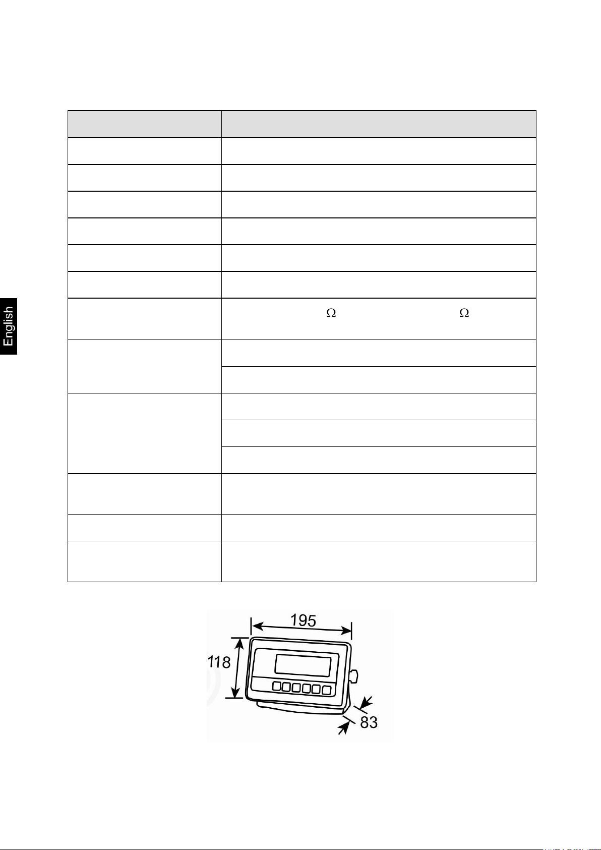
1 Technical data
KERN
KFE-TM
Display
6-digit
Solution verifiable
6.000 e
Verification class
III
Weighing ranges
2
Divisions
1,2,5,…10, n
Display
LCD 22 mm digits with back lighting
DMS weighing cells
80-100 . Max. 4 items per 350 ;
Sensitivity 2-3 mV/V
Electric Supply
Input voltage 220 V – 240 V, 50 Hz
Mains adapter secundary voltage 12V, 500 mA
Rechargeable battery
(optional)
6 x 1.5 V, 4 Ah
Service life – background illumination OFF 45 h
Loading time 12 h
Admissible
ambient temperature
-10°C – 40°C
Net weight
1.9 kg
Protection type
IP 65 as per DIN EN 60529
Dimensions:
4 KFE-TM-BA_IA-e-1313
Page 5

2 Appliance overview
Front view:
1. Weight display
2. Keyboard
Rear view:
3. Wall bracket
4. Connection power supply (mains adapter)
5. Fastening screws
6. Connection platform
7. Position of seal / housing screw
KFE-TM-BA_IA-e-1313 5
Page 6
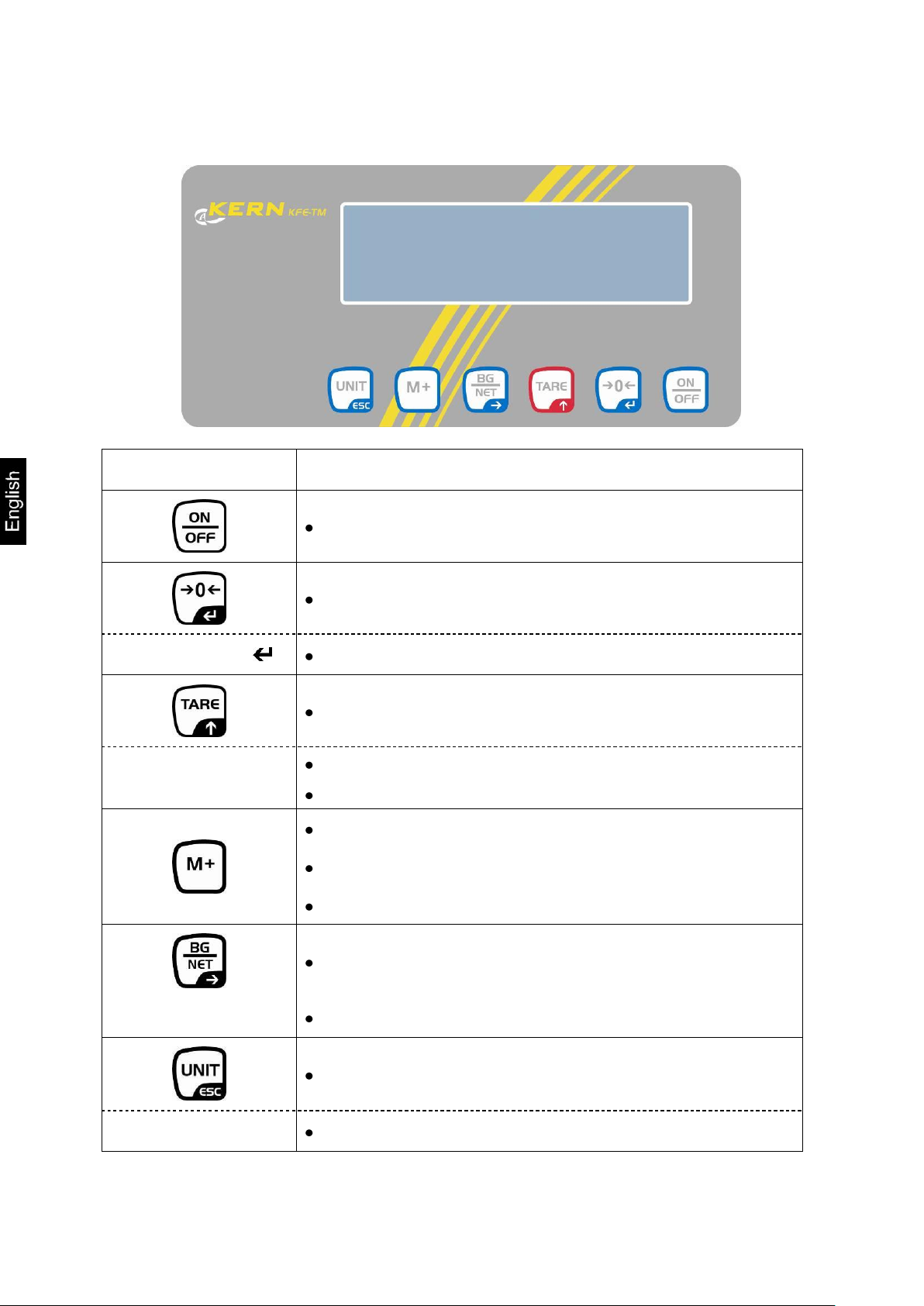
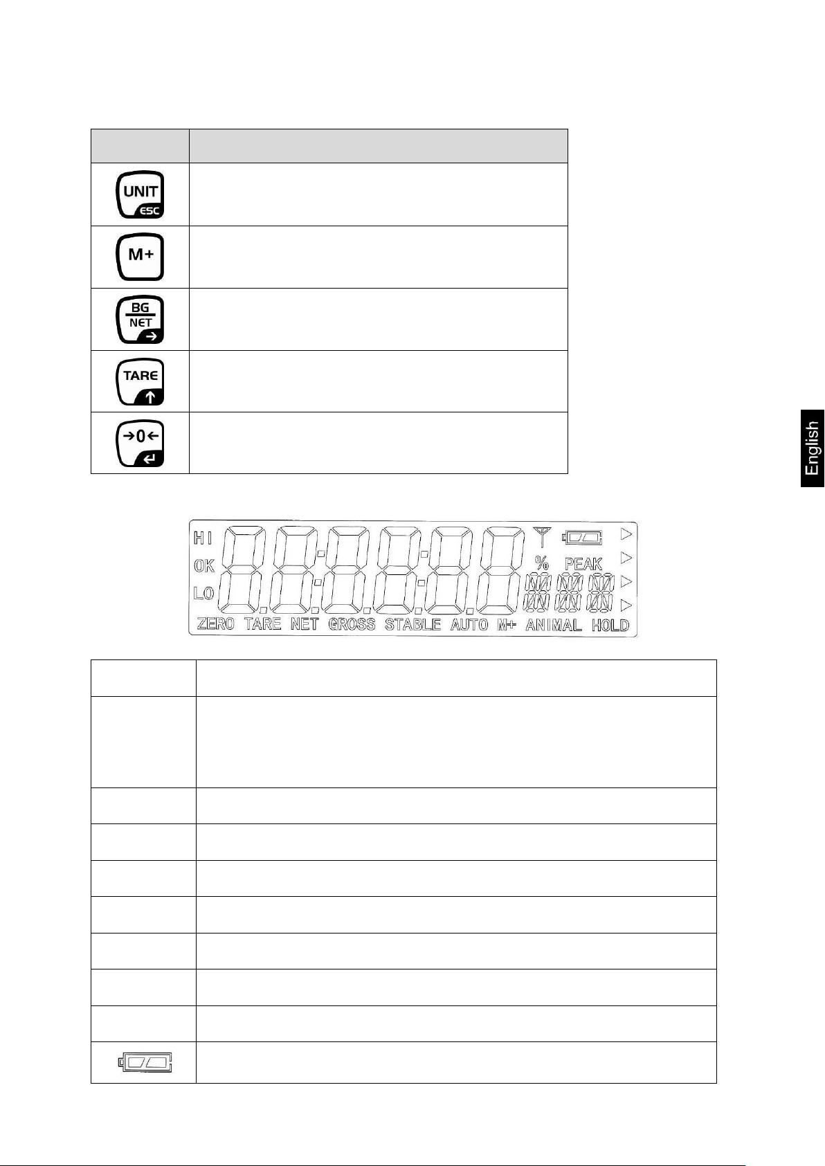
2.1 Keyboard overview
Key
Function
Turn on/off
Zeroing
Navigation key
Confirm entry
Taring
Navigation key
Scroll forward in menu
At numeric input increase flashing digit
Add weighing value to summation memory
Display sum total
Delete total added memory
Change between gross and net weight
Navigation key
Digit selection to the right
Switch-over weighing unit
ESC
Back to menu/weighing mode
6 KFE-TM-BA_IA-e-1313
Page 7
2.1.1 Numerical input via the navigation buttons
Key
Function
Digit selection to the left
Delete
Digit selection to the right
Increase flashing digit
Terminate input
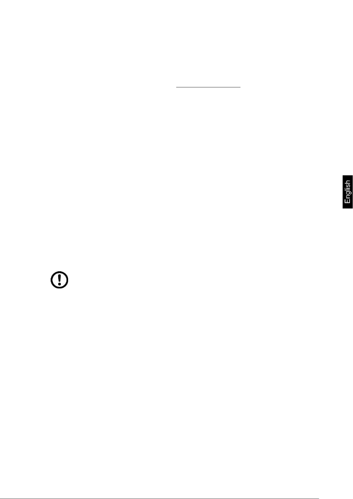
Display
Significance
HI
OK
LO
Status indicatoren for weighing with tolerance range
HI: Weighed goods over default tolerance
OK: Weighed goods within default tolerance
OK: Load below specified tolerance
ZERO
Indicator zero display
TARE
Indicator for saved tare value
NET
The displayed weighing value is a net weighing value
GROSS
The displayed weighing value is a gross weighing value
STABLE
Stability display
AUTO
Function for „Automatic totalizing“ is activated
ANIMAL
Animal weighing mode is activated
Charging status of rechargeable battery (optional)
2.2 Overview of display
KFE-TM-BA_IA-e-1313 7
Page 8

3 Basic Information (General)
3.1 Proper use
The display unit acquired by you is used in combination with a weighing plate and
serves to determine the weighing value of material to be weighed. It is intended to be
used as a “non-automatic weighing system”, i.e. the material to be weighed is
manually and carefully placed in the centre of the weighing plate. As soon as a
stable weighing value is reached the weighing value can be read.
3.2 Improper Use
Do not use display unit for dynamic weighings. In the event that small quantities are
removed or added to the material to be weighed, incorrect weighing results can be
displayed due to the “stability compensation“ in the display unit. (Example: Slowly
draining fluids from a container on the balance)
Do not leave permanent load on the weighing plate. This may damage the
measuring system.
Impacts and overloading exceeding the stated maximum load (max) of the weighing
plate, minus a possibly existing tare load, must be strictly avoided. Both, the
weighing plate and the display unit may be damaged during this process.
Never operate display unit in explosive environment. The serial version is not
explosion protected.
Changes to the display unit's design are not permitted. This may lead to incorrect
weighing results, safety-related faults and destruction of the display unit.
The display unit may only be operated in accordance with the described default
settings. Other areas of use must be released by KERN in writing.
3.3 Warranty
Warranty claims shall be voided in case
Our conditions in the operation manual are ignored
The appliance is used outside the described uses
The appliance is modified or opened
Mechanical damage or damage by media, liquids, natural wear and tear
The appliance is improperly set up or incorrectly electrically connected
The measuring system is overloaded
8 KFE-TM-BA_IA-e-1313
Page 9
3.4 Monitoring of Test Resources
Keep all parts of the original packaging for a possibly
required return.
Only use original packaging for returning.
Prior to dispatch disconnect all cables and remove
loose/mobile parts.
Reattach possibly supplied transport securing devices.
Secure all parts such as the glass wind screen, the
weighing platform, power unit etc. against shifting and
damage.
In the framework of quality assurance the measuring-related properties of the display
unit and, if applicable, the testing weight, must be checked regularly. The responsible
user must define a suitable interval as well as type and scope of this test. Information
is available on KERN’s home page (www.kern-sohn.com with regard to the
monitoring of display units’ test substances and the test weights required for this. In
KERN’s accredited DKD calibration laboratory test weights and display units may be
calibrated (return to the national standard) fast and at moderate cost.
4 Basic Safety Precautions
4.1 Pay attention to the instructions in the Operation Manual
Carefully read this operation manual before setup and commissioning, even if you
are already familiar with KERN balances.
4.2 Personnel training
The appliance may only be operated and maintained by trained personnel.
5 Transport and storage
5.1 Testing upon acceptance
When receiving the appliance, please check packaging immediately, and the
appliance itself when unpacking for possible visible damage.
5.2 Packaging / return transport
KFE-TM-BA_IA-e-1313 9
Page 10
6 Unpacking and installation
For display unit, see chapter 2
Mains adapter
Operating instructions
6.1 Installation Site, Location of Use
The display units are designed in a way that reliable weighing results are achieved in
common conditions of use. Precise and fast work is achieved by selecting the right
place for your display unit and your weighing plate.
On the installation site observe the following:
Place the display unit and the weighing plate on a stable, even surface.
Avoid extreme heat as well as temperature fluctuation caused by installing
next to a radiator or in the direct sunlight;
Protect the display unit and the weighing plate against direct draft from open
windows or doors.
Avoid jarring during weighing;
Protect the display unit and the weighing plate against high humidity, vapours
and dust.
Do not expose the display unit to extreme dampness for longer periods of
time. Non-permitted condensation (condensation of air humidity on the
appliance) may occur if a cold appliance is taken to a considerably warmer
environment. In this case, acclimatize the disconnected appliance for ca. 2
hours at room temperature.
Avoid static charge of goods to be weighed or weighing container.
Major display deviations (incorrect weighing results) may be experienced should
electromagnetic fields (e.g. due to mobile phones or radio equipment), static
electricity accumulations or instable power supply occur. Change location or remove
source of interference.
6.2 Unpacking and installation
Take the display unit carefully out of its packaging, remove the plastic jacket and
install it at the designated work space. Mount the display unit in a way that facilitates
operation and where it is easy to see.
6.3 Scope of delivery / serial accessories:
10 KFE-TM-BA_IA-e-1313
Page 11
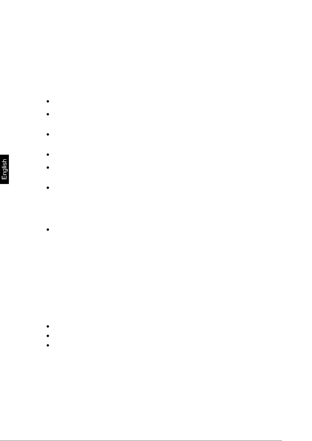
6.4 Transit Securing
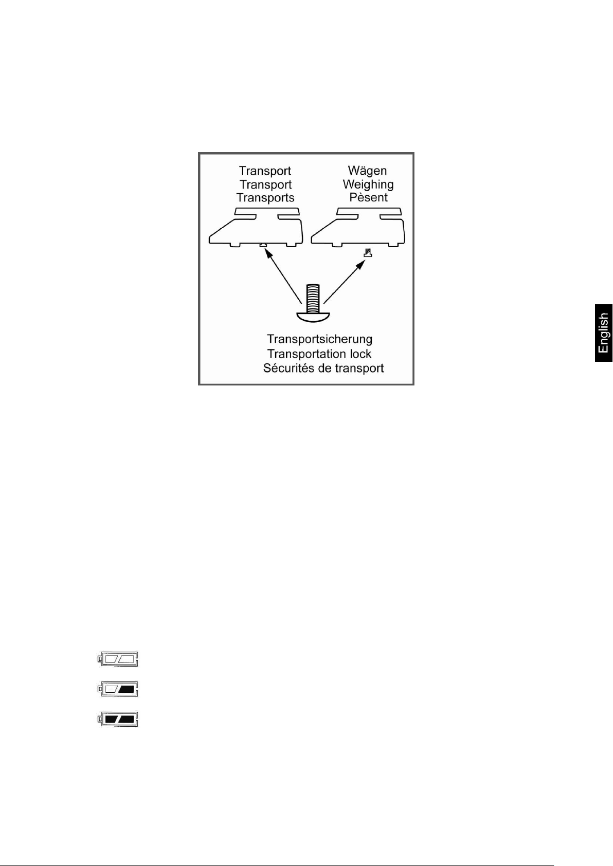
Voltage has dropped below prescribed minimum.
Battery very low.
Battery is completely discharged
Please note, if the display unit is used together with platform with transportation lock,
this transportation lock must be released prior to use.
See operating instructions attached to the respective platform.
6.5 Mains connection
Power is supplied via the external mains adapter. The stated voltage value must be
the same as the local voltage.
Only use original KERN mains adapters. Using other makes requires consent by
KERN.
6.6 Storage battery operation (optional)
Before the first use, the battery should be charged by connecting it to the mains
power supply for at least 12 hours.
The appearance of the rechargeable battery symbol in the weight display indicates
that the battery is almost exhausted. The unit will be ready for operation for approx.
another 10 hours before switching off automatically. Charge the battery with the help
of the supplied power pack.
The rechargeable battery symbol shows the charge status of the rechargeable
battery:
KFE-TM-BA_IA-e-1313 11
Page 12
6.7 Adjustment
The adjustment is locked for verified balances.
In order to unlock the access, the seal must be destroyed and the
jumper on the printed circuit board must be fitted (see chap. 6.9).
Attention:
After destruction of the seal the weighing system must be re-verified by
an authorised agency and a new verification wire/seal mark fitted before
it can be reused for applications subject to verification.
The weight to be used depends on the capacity of the scale. Carry out
adjustment as near as possible to the scale’s maximum weight. Info
about test weights can be found on the Internet at: http://www.kernsohn.com.
Observe stable environmental conditions. Stabilisation requires a
certain warm-up time.
As the acceleration value due to gravity is not the same at every location on earth,
each display unit with connected weighing plate must be coordinated - in compliance
with the underlying physical weighing principle - to the existing acceleration due to
gravity at its place of location (only if the weighing system has not already been
adjusted to the location in the factory). This adjustment process must be carried out
for the first commissioning, after each change of location as well as in case of
fluctuating environment temperature. To receive accurate measuring values it is also
recommended to adjust the display unit periodically in weighing operation.
12 KFE-TM-BA_IA-e-1313
Page 13
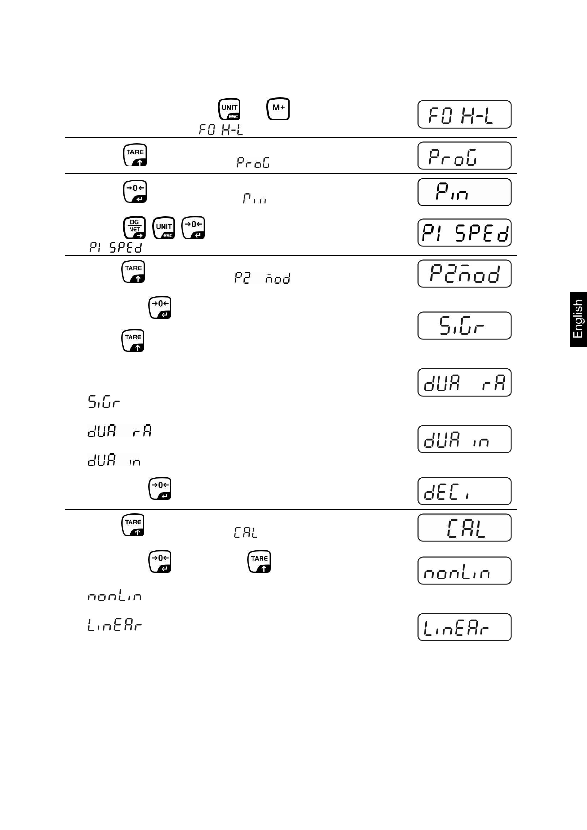
Call-up menu
In weighing mode press and at the same time and
the first menu block will appear.
Press repeatedly until is displayed.
Press , password query will appear.
Press , , subsequently until the first menu item
is shown.
Press repeatedly until is displayed.
Confirm by .
Press repeatedly until the currently balance typ will be
displayed.
= Singel range
= Dual range
= Multi interval
Confirm by .
Press repeatedly until
will be displayed.
Confirm by and select by .
= Justierung
= Linearisierung
KFE-TM-BA_IA-e-1313 13
Page 14
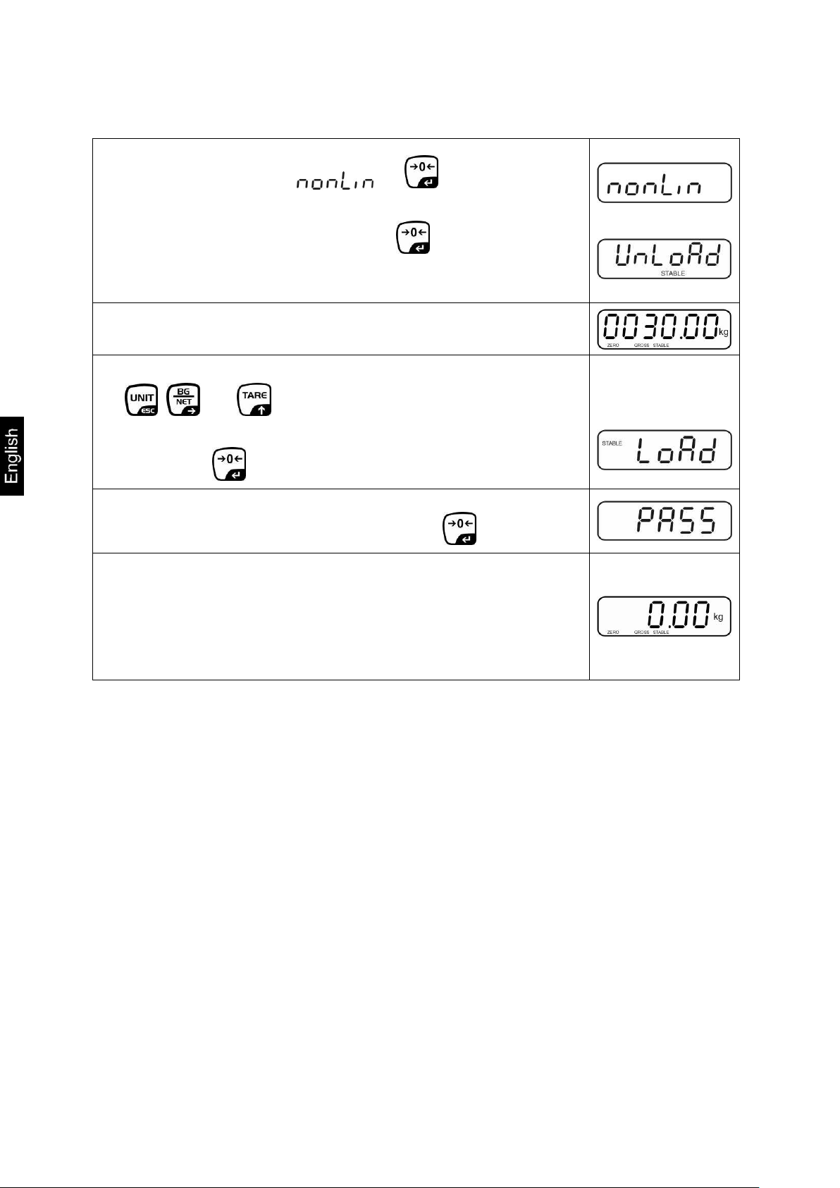
Procedure
Confirm menu setting by .
Ensure that there are no objects on the weighing plate.
Wait for stability display, then press .
The currently set adjustment weight will be displayed.
Either use the displayed adjustment weight or change it with
, and (numerical input see chapter 2.1.1), the
active digit is flashing.
Confirm by , „LoAd“ will be shown.
Carefully place adjusting weight in the centre of the weighing
plate. Wait for stability display, then press .
After the adjustment the balance will carry out a self-test.
Remove adjusting weight during selftest, balance will return
into weighing mode automatically.
An adjusting error or incorrect adjusting weight will be
indicated by the error message; repeat adjustment
procedure.
14 KFE-TM-BA_IA-e-1313
Page 15

6.8 Linearization
Carrying out linearization is restricted to specialist staff possessing well
acquainted with the workings of weighing scales.
The linearisation is locked for verified weighing systems.
In order to unlock the access, the seal must be destroyed and the
jumper on the printed circuit board must be fitted (see chap. 6.9).
Attention:
After destruction of the seal the weighing system must be re-verified by
an authorised agency and a new verification wire/seal mark fitted before
it can be reused for applications subject to verification.
The test weights to be used must be adapted to the weighing scale’s
specifications; see chapter 3.4 “testing instruments control”.
Observe stable environmental conditions. Stabilisation requires a
certain warm-up time.
After successful linearization you will have to carry out calibration; see
chapter “testing instruments control”
Procedure:
Call-up menu setting , see chap. 6.7.
Acknowledge with .
Ensure that there are no objects on the weighing plate.
Wait for stability display „STABLE“, then press . When
“LoAd 1“ is displayed, put the first adjustment weight (1/3
max) carefully in the centre of the weighing platform.
Wait for stability display „STABLE“, then press . When
“LoAd 2“ is displayed, put the second adjustment weight
(2/3 max) carefully in the centre of the weighing platform.
Linearity shows the greatest deviation of a weight display on the scale to the value of
the respective test weight according to plus and minus over the entire weighing
range.
If linearity deviation is discovered during a testing instrument control, you can
improve this by means of linearization.
KFE-TM-BA_IA-e-1313 15
Page 16
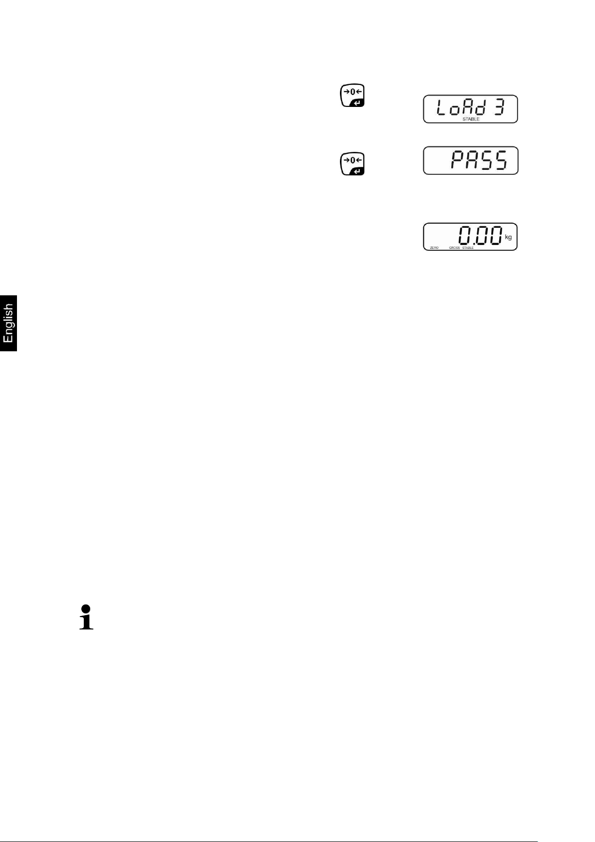
Wait for stability display „STABLE“, then press . When
“LoAd 3“ is displayed, put the third adjustment weight (1/3
max) carefully in the centre of the weighing platform.
Wait for stability display „STABLE“, then press .
After the adjustment the balance will carry out a self-test.
Remove adjusting weight during selftest, the appliance will
return into weighing mode automatically.
An adjusting error or incorrect adjusting weight will be
indicated by the error message; repeat adjustment
procedure.
Verification of the balance is invalid without the seal.
The seal marks attached on verified balances point out that the balance may
only be opened and serviced by trained and authorised specialist staff. If the
seal mark is destroyed, verification looses its validity. Please observe all
national laws and legal regulations. In Germany a re-verification will be
necessary.
6.9 Verification
General introduction:
According to EU directive 90/384/EEC or 2009/23EG balances must be officially
verified if they are used as follows (legally controlled area):
a) For commercial transactions if the price of goods is determined by weighing.
b) For the production of medicines in pharmacies as well as for analyses in the
medical and pharmaceutical laboratory.
c) For official purposes
d) For manufacturing final packages
In cases of doubt, please contact your local trade in standard.
Verification notes:
An EU type approval exists for balances described in their technical data as
verifyable. If a balance is used where obligation to verify exists as described above, it
must verified and re-verified in regular intervals.
Re-verification of a balance is carried out according to the respective national
regulations. The validity for verification of balances in Germany is e.g. 2 years.
The legal regulation of the country where the balance is used must be observed!
16 KFE-TM-BA_IA-e-1313
Page 17
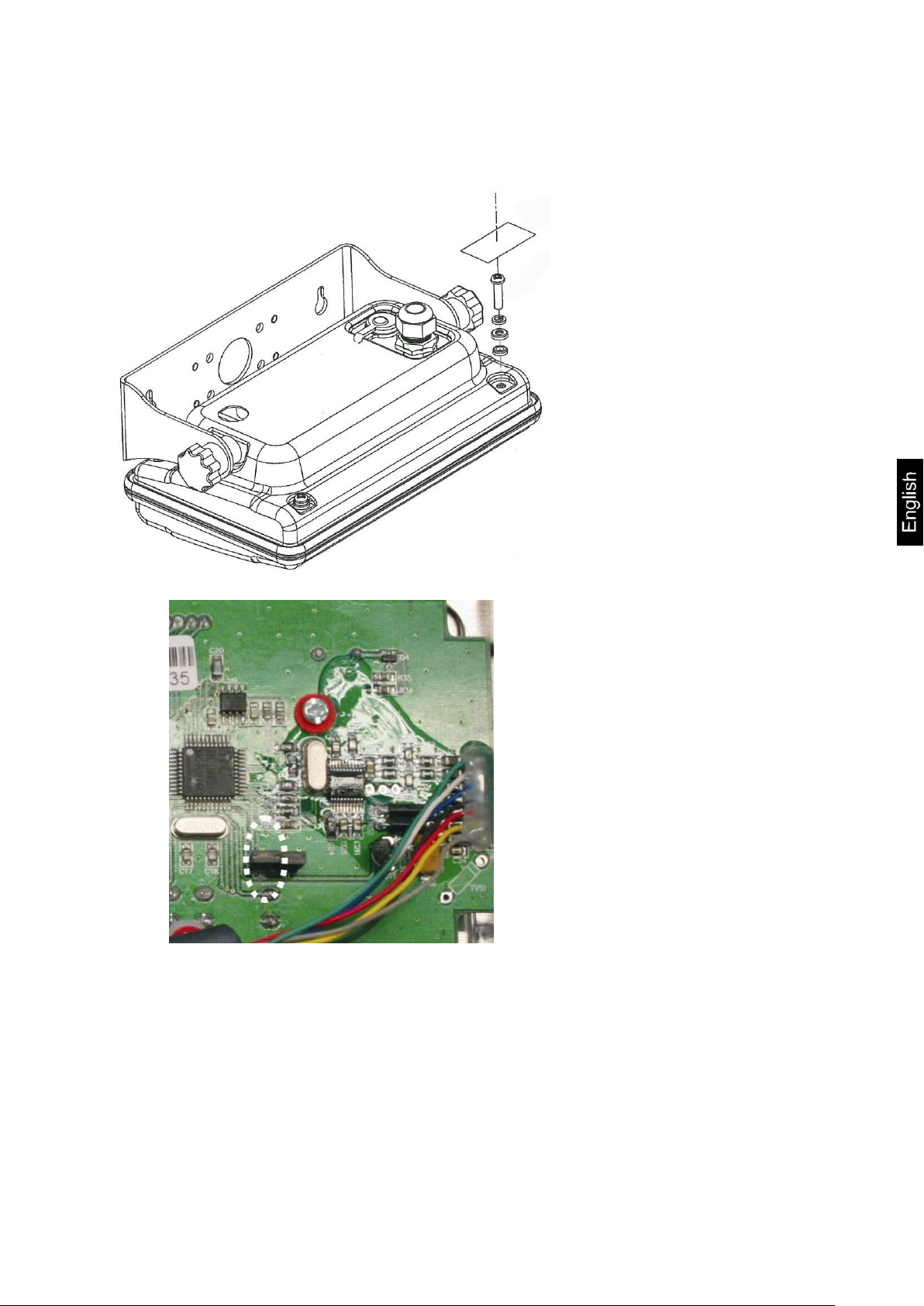
Position of seals and jumper
Remove seal
Open display unit
For adjustment / access
to the configuration
menu the jumper „CAL“
must be fitted.
Access to conductor plate:
KFE-TM-BA_IA-e-1313 17
Page 18
7 Operation
Overload warning
Overloading exceeding the stated maximum load (max) of the device, minus
a possibly existing tare load, must be strictly avoided. This could damage the
instrument.
Exceeding maximum load is indicated by the display of “ol“, and an audio
sound. Unload weighing system or reduce preload.
7.1 Start-up
Press and the instrument will carry out a self-test. As soon as the weight
display appears, the instrument will be ready to weigh.
7.2 Switching Off
Press and the display will disappear.
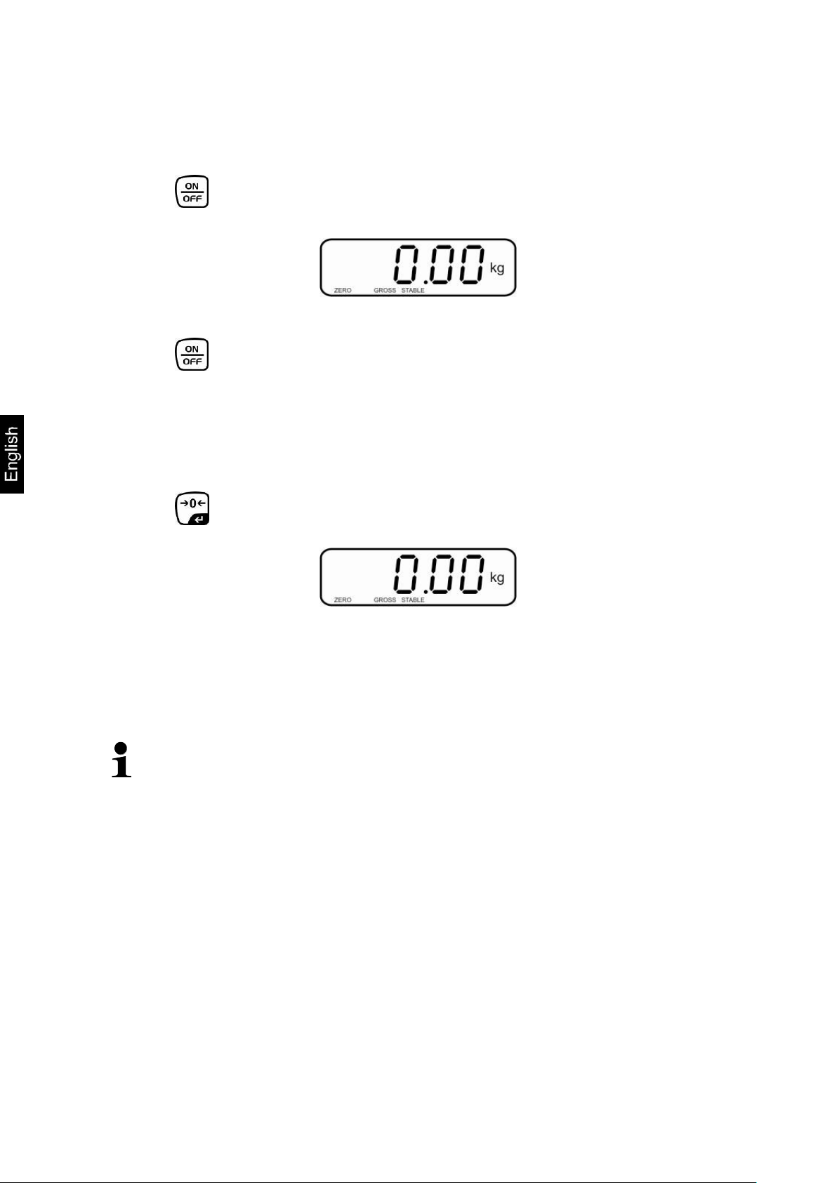
7.3 Zeroing
Resetting to zero corrects the influence of light soiling on the weighing plate.
To unload the weighing system
Press and zero display as well as indicator ZERO will appear.
7.4 Simple weighing
Place goods to be weighed on balance.
Wait until stability display STABLE appears.
Read weighing result.
18 KFE-TM-BA_IA-e-1313
Page 19

7.5 Weighing with taring
Selectable mode
Description
bp 1
Acoustic signal switched off, only optical signal active
[LO], [OK] or [HI]
bp 2
If load is within tolerance range, [ok] will be displayed
and audio signal will be sounded.
bp 3
If the load is beyond the tolerance range [ok] will be
shown and the audio signal will sound.
Deposit weighing vessel. After successful stop check press the button. Zero
display and indicator NET appear.
The weight of the container is now internally saved.
Weigh the material, the net weight will be indicated.
After removing the weighing container, the weight of the weighing container
appears as negative display.
The taring process can be repeated any number of times, e.g. when adding
several components for a mixture (adding). The limit is reached when the whole
weighing range is exhausted.
To change between gross weight and net weight, press .
To delete the tare value, remove load from weighing plate and press .
7.6 Weighing with tolerance range
You can set an upper or lower limit when weighing with tolerance range and thus
ensure that the weighed load remains exactly within the set limits.
During tolerance controls such as dispensing, portioning or sorting the unit will
indicate whether a value exceeds or falls short of limits with an optical [LO, OK, HI]
as well as an audio signal according to the setting in the menu block “F4
oFF_BEEP“; see chapter 8.2.
KFE-TM-BA_IA-e-1313 19
Page 20

1. Call up menu
In weighing mode press and at the same time and
the first menu block will appear.
2. Set limit values
Keep on pressing until the display used for entering the
lower limit SET LO appears.
Press and current setting will be displayed.
To enter the lower limit, e. g. 1000 Kg, press the navigation
keys (See chpt. 2.1.1); the currently enabled digit will be
flashing.
Confirm input by .
Select SET HI by pressing .
Press and the current setting for the upper limit will be
displayed.
Press the navigation keys (See chpt. 2.1.1) to enter the
upper limit, e.g. 1,100 kg; the currently enabled digit will be
flashing.
Confirm input by .
Press and the unit will return to the menu
20 KFE-TM-BA_IA-e-1313
Page 21

3. How to set tolerance weighing mode
Press repeatedly until is displayed.
Acknowledge with .
Press repeatedly until BEEP is displayed.
Press and current setting will be displayed.
Select desired setting (bp 1, bp 2, bp 3) with and
confirm by pressing .
Press repeatedly to exit menu. The weighing system is
in tolerance weighing mode, i.e. from here occurs the
graduation if the weighed material is within the two tolerance
limits.
4. Weighing with tolerance range
Tare when using a weighing container
Put on goods to be weighed, tolerance control is started
Load below specified
tolerance
Load within specified
tolerance
Load exceeds specified
tolerance
The indicator [LO] is
displayed
The indicator [OK] is
displayed
The indicator [HI] is
displayed
The tolerance control is not active when the weight is under 20d.
To delete limits, enter “00.000 kg“.
KFE-TM-BA_IA-e-1313 21
Page 22

7.7 Manual totalizing
Menu settings:
„F5 Prt“ „P prt“, see chap. 8.2
“P4 CHk“ „mode 1“, see chap. 11.4
The totalizing function is not active when the weight is under 20d.
Add up:
Place weighing goods A.
Wait until the stability display STABLE appears, then press . The weighing
value is saved.
Remove the weighed good. More weighed goods can only be added when the
display ≤ zero.
Place goods to be weighed B.
Wait until the stability display appears, then press . The weighing value is
added into the summation memory. Number of weighing, followed by the total
weight will be displayed for 2 sec.
Add more weighed goods as described before.
Please note that the weighing system must be unloaded between the individual
weighing procedures.
You can repeat this process 99 times until the capacity (max) of the weighing
system is exhausted.
Display of the saved weighing data:
When zero is displayed press , the number of weighings followed by the total
weight will be displayed for 2 sec.
With this function the individual weighing values are totalized into the sum memory
by pressing .
22 KFE-TM-BA_IA-e-1313
Page 23

Delete weighing data:
If you see a display of zero, press and the number of weighing, followed by
the total weight will be shown for 2 sec. Press during this display.
The data in the summation memory are deleted.
KFE-TM-BA_IA-e-1313 23
Page 24

7.8 Automatic adding-up
Menu settings:
„F5 Prt“ „P prt“, see chap. 8.2
“P4 CHk“ „mode 1“, see chap. 11.4
When function is activated, the indicator AUTO appears.
Add up:
Place weighing goods A.
After the standstill control sounds a signal tone.
Unload the weighing good, the weighing value is added into the summation
memory.
More weighed goods can only be added when the display ≤ zero.
Place goods to be weighed B.
After the standstill control sounds a signal tone. Unload the weighing good, the
weighing value is added into the summation memory. Number of weighing,
followed by the total weight will be displayed for 2 sec.
Add more weighed goods as described before.
Please note that the weighing system must be unloaded between the individual
weighing procedures.
You can repeat this process 99 times until the capacity (max) of the weighing
system is exhausted.
After the audio sound was sounded you can remove the load or add to it.
Display and delete weighing data see chap. 7.7.
This function is used to issue and add individual weighing values automatically to the
summation memory on unloading of weighing scale without pressing .
24 KFE-TM-BA_IA-e-1313
Page 25

7.9 Animal weighing
Menu setting:
, see chap. 11.4
When function is activated, the indicator ANIMAL appears.
Place goods to be weighed on balance.
When the load has somewhat calmed down, you will hear an audio sound. The
mean value achieved will be shown.
Whilst averaging is taking place you can add or remove loads as the measuring
value will be constantly updated.
To disable the animal weighing function, return to weighing mode
Select menu setting , see chpt. 11.4.
The mean value function is suitable for weighing restless loads.
KFE-TM-BA_IA-e-1313 25
Page 26

8 Menu
Call up menu
In weighing mode press and at the same time
and the first menu block will appear.
Select menu block
With help of , the individual menu blocks can be
selected one after the other.
Select setting
Confirm selected menu item by pressing . The
current setting will be displayed.
Change settings
To change to the available settings, press the
navigations keys as described in chpt. 2.1.1.
Acknowledge setting /
exit the menu
Either save by pressing or cancel by pressing .
Return to weighing
mode
Press repeatedly to exit menu.
Menu block
Menu item
Available settings / explanation
Weighing with
tolerance range
SET Lo
Upper limit value, input see chapter 7.6
(factory setting 000.000)
SET Hi
Lower limit value, input see chapter 7.6
(factory setting 000.000)
to Clr
Not documented
to P-C
Not documented
to Prt
Not documented
Weighing Units
Factory setting „kg“, no further units available.
Date/time
SET dA
Set date
Press and the currently set date (yy.mm.dd)
will be displayed. To make changes, press the
navigation keys as explained in chpt. 2.1.1.
SET ti
Set time
Press and the currently set time (hh.m.ss) will
be displayed. To make changes, press the
navigation keys as explained in chpt. 2.1.1.
8.1 Navigation in the menu
8.2 Overview
26 KFE-TM-BA_IA-e-1313
Page 27

Clock
Clk on
Display time switched on
After 5 min without change of load the weight
display passes to the time display.
Clk of*
Display of time OFF
bl
bk on
Background lighting of display is switched on
permanently
bk AU
Display background illumination off
bk off
Automatic background illumination on when
weighing pate is loaded or key pressed.
bEEP
see chpt
7.6
bp 1
Audio signal switched off during tolerance
weighing
bp 2
If load is within tolerance, [ok] will be displayed
and audio signal will be sounded
bp 3
If the load is beyond the tolerance range, [ok]
will be shown and the audio signal will sound.
P Prt
Manual totalizing, see chap. 7.7
P Cont
Not documented
Series
Not documented
ASK
Not documented
P cnt 2
Not documented
P Stab
A Not documented
P Auto
For automatic totalizing see chpt. 7.8.
Confirm selection by , after that the following menu items are
available.
b9600
Not documented
Pr X
Lab X
Ty-tp
Ty 711
Lp 50
St on
Following tare ON
St off
Following tare OFF
Access to configuration menu see chap. 11.4
KFE-TM-BA_IA-e-1313 27
Page 28

9 Service, maintenance, disposal
Before any maintenance, cleaning and repair work disconnect the
appliance from the operating voltage.
9.1 Cleaning
Keep IP protection.
Clean the stainless-steel parts with a soft cloth soaked with a cleaning agent
suitable for stainless steel.
For stainless steel parts do not use any cleaning agents which contain sodium
hydroxide solution, acetic, hydrochloric, sulphuric or citric acid.
Do not use metal brushes or cleaning sponges of steel wool, as this causes
superficial corrosion.
9.2 Service, maintenance
The appliance may only be opened by trained service technicians who are
authorized by KERN.
Ensure that the balance is regularly calibrated, see chap. Testing instruments
control.
9.3 Disposal
Disposal of packaging and appliance must be carried out by operator
according to valid national or regional law of the location where the appliance
is used.
28 KFE-TM-BA_IA-e-1313
Page 29

9.4 Error messages
Error
message
Description
Possible causes
- - - - -
Maximum load exceeded
Unload weighing system or reduce
preload.
- - ol - -
Err 1
Incorrect data input
Follow format “yy:mm:dd“
Err 2
Incorrect time entry
Follow format “hh:mm:ss“
Err 4
Zeroing range exceeded due
to switching-on balance or
pressing
(normally 4% max)
Object on the weighing plate
Overload when zeroing
Err 5
Keyboard error
Err 6
Value outside the A/D
changer range
Weighing plate not installed
Damaged weighing cell
Damaged electronics
Err 9
Stability display does not
appear
Check the environmental
conditions.
Err 17
Taring range exceeded
Reduce load
Fai l h /
Fai l l
Adjustment error
Repeat adjustment.
Ba lo /
Lo ba
Battery very low
Recharge battery
Should other error messages occur, switch balance off and then on again. If the error
message remains inform manufacturer.
KFE-TM-BA_IA-e-1313 29
Page 30

10 Instant help
Fault
Possible cause
The displayed weight does
not glow.
The display unit is not switched on.
Mains power supply interrupted (mains cable
defective).
Power supply interrupted.
(Rechargeable) batteries are inserted incorrectly or
empty
No (rechargeable) batteries inserted.
The displayed weight is
permanently changing
Draught/air movement
Table/floor vibrations
Weighing plate has contact with other objects.
Electromagnetic fields / static charging (choose
different location/switch off interfering device if
possible)
The weighing result is
obviously incorrect
The display of the balance is not at zero
Adjustment is no longer correct.
Great fluctuations in temperature.
Warm-up time was ignored.
Electromagnetic fields / static charging (choose
different location/switch off interfering device if
possible)
In case of an error in the program process, briefly turn off the display unit and
disconnect from power supply. The weighing process must then be restarted from
the beginning.
Help:
30 KFE-TM-BA_IA-e-1313
Page 31

11 Installing display unit / weighing bridge
Installation / configuration of the weighing system must be carried out by a
well acquainted specialist with the workings of weighing balances.
Supply voltage:
5 V/150mA
Max. signal voltage
0 15 mV
Zeroing range
0 5 mV
Sensitivity
2-3 mV/V
Resistance parameter
80 - 100 Ω, max 4 items per 350 Ω load cell
11.1 Technical data
11.2 Weighing system design
The display unit is suitable for connection to any analogue platform in compliance
with the required specifications.
The following data must be established before selecting a weighing cell:
Weighing balance capacity
This usually corresponds to the heaviest load to be weighed.
Preload
This corresponds to the total weight of all parts that are to be placed on the
weighing cell such as upper part of platform, weighing pan etc.
Total zero setting range
This is composed of the start-up zero setting range (± 2%) and the zero
setting range available to the user via the ZERO-key (2%). The total zero
setting range equals therefore 4 % of the scale’s capacity.
The addition of weighing scales capacity, preload and the total zero setting
range give the required capacity for the weighing cell.
To avoid overloading of the weighing cell, include an additional safety
margin.
Smallest desired display division
KFE-TM-BA_IA-e-1313 31
Page 32

11.3 How to connect the platform
Disconnect device from mains.
Pull load cell cable into the display unit through the screwable cable attachment.
Weld the individual wires of the load cell cable to the printed circuit board,
see fig. 1. Details can be seen in the technical data of the load cell.
Fig. 1
32 KFE-TM-BA_IA-e-1313
Page 33

11.4 Configure display unit
Call-up configuration menu:
In weighing mode press and at the same time and the first menu
block will appear.
Press repeatedly until is displayed.
Press , password query will appear.
Press , , subsequently until the first menu item is
shown.
Navigation in the menu
With help of , the individual menu items can be selected one after the
other.
Confirm selected menu item by pressing . The current setting will be
displayed.
Switch into the available settings using .
Either save by pressing or cancel by pressing .
Press repeatedly to exit menu.
KFE-TM-BA_IA-e-1313 33
Page 34

Configuration menu overview:
Menu block
Main menu
Menu item
Submenu
Available settings / explanation
Not documented
Single-range balance
Confirm by , after that the following menu items are
available.
Position decimal point
available selection 0, 0.0, 0.00, 0.000,
0.0000
Readability/verification value
selectable 1, 2, 5, 10, 20, 50
Balance capacity (max)
Adjust weighing system according to configuration.
Adjustment, see chap. 6.7
For linearisation see chapter 6.8
34 KFE-TM-BA_IA-e-1313
Page 35

Dual range balance
Confirm by , after that the following menu items are
available.
Position decimal point available
selection 0, 0.0, 0.00, 0.000, 0.0000
Readability / verification
value for
1. Weighing range
Selectable 1, 2, 5, 10, 20,
50
Readability / verification
value for
2. Weighing range
Selectable 1, 2, 5, 10, 20,
50
Balance capacity (Max) 1st weighing
range
Balance capacity (Max) 2nd weighing
range
Adjust weighing system according to configuration.
Adjustment, see chap. 6.7
For linearisation see chap. 6.8
KFE-TM-BA_IA-e-1313 35
Page 36

Multi-interval balance
Confirm by , after that the following menu items are
available.
Position decimal point available
selection 0, 0.0, 0.00, 0.000, 0.0000
Readability / verification
value for
1. Weighing range
Selectable 1, 2, 5, 10, 20,
50
Readability / verification
value for
2. Weighing range
Selectable 1, 2, 5, 10, 20,
50
Balance capacity (Max) 1st weighing
range
Balance capacity (Max) 2nd weighing
range
Adjust weighing system according to configuration.
Adjustment, see chap. 6.7
For linearisation see chapter 6.8
Not documented
Internal A/D converter value
Reset to default setting
Not documented
Weighing mode
(tolerance weighing, totalizing)
Animal weighing mode
Not documented
Not documented
12 Enclosure Declaration of conformity / Type approval /
Test certificate
36 KFE-TM-BA_IA-e-1313
Page 37

KERN & Sohn GmbH
D-72322 Balingen-Frommern
Postfach 4052
E-Mail: info@kern-sohn.de
Tel: 0049-[0]7433- 9933-0
Fax: 0049-[0]7433-9933-149
Internet: www.kern-sohn.de
D
Konformitätserklärung
Wir erklären hiermit, dass das Produkt, auf das sich diese Erklärung bezieht,
mit den nachstehenden Normen übereinstimmt.
GB
Declaration of
conformity
We hereby declare that the product to which this declaration refers conforms
with the following standards.
CZ
Prohlášení o
shode
Tímto prohlašujeme, že výrobek, kterého se toto prohlášení týká, je v souladu
s níže uvedenými normami.
E
Declaración de
conformidad
Manifestamos en la presente que el producto al que se refiere esta
declaración está de acuerdo con las normas siguientes
F
Déclaration de
conformité
Nous déclarons avec cela responsabilité que le produit, auquel se rapporte la
présente déclaration, est conforme aux normes citées ci-après.
I
Dichiarazione di
conformitá
Dichiariamo con ciò che il prodotto al quale la presente dichiarazione si
riferisce è conforme alle norme di seguito citate.
NL
Conformiteitverklaring
Wij verklaren hiermede dat het product, waarop deze verklaring betrekking
heeft, met de hierna vermelde normen overeenstemt.
P
Declaração de
conformidade
Declaramos por meio da presente que o produto no qual se refere esta
declaração, corresponde às normas seguintes.
PL
Deklaracja
zgodności
Niniejszym oświadczamy, że produkt, którego niniejsze oświadczenie dotyczy,
jest zgodny z poniższymi normami.
RUS
Заявление о
соответствии
Мы заявляем, что продукт, к которому относится данная декларация,
соответствует перечисленным ниже нормам.
EU Directive
Standards
2004/108/EC
EN55022: 2006 A1:2007
EN61000-3-3:1995+A1:2001+A2:2005
EN55024: 1998+A1:2001+A2:2003
2006/95/EC
EN 60950-1:2006
EN 60065:2002+A1:2006
Signatur
Signature
Datum
Date
08.04.2013
Ort der Ausstellung
Place of issue
72336 Balingen
Albert Sauter
KERN & Sohn GmbH
Geschäftsführer
Managing director
KERN & Sohn GmbH, Ziegelei 1, D-72336 Balingen, Tel. +49-[0]7433/9933-0
Fax +49-[0]7433/9933-149, E-Mail: info@kern-sohn.com, Internet: www.kern-sohn.com
Declaration of conformity
EG-Konformitätserklärung EC-Declaration of -Conformity
EC- Déclaration de conformité EC-Declaración de Conformidad
EC-Dichiarazione di conformità EC-Conformiteitverklaring
EC- Declaração de conformidade EC- Prohlášení o shode
EC-Deklaracja zgodności EC-Заявление о соответствии
Electronic Balance: KERN KFF-T; KFE-TM; SFE
KFE-TM-BA_IA-e-1313 37
Page 38

Page 39

Annex page 1 of 12
EC type-approval certificate no. DK 0199.312
Descriptive annex
Contents Page
1. Name and type of instrument and modules 2
2. Description of the construction and function 2
2.1 Construction 2
2.2 Functions 2
3. Technical data 4
3.1 Indicator 4
3.2 Load receptors, load cells and load receptor supports 5
3.3 Composition of modules 5
3.4 Documents 5
4. Interfaces and peripheral equipment 6
4.1 Interfaces 6
4.2 Peripheral equipment 6
5. Approval conditions 6
5.1 Measurement functions other than non-automatic functions 6
5.2 Totalised weight is not a legal value. 6
5.3 Compatibility of modules 6
6. Special conditions for verification 6
6.1 Composition of modules 6
7. Securing and location of seals and verification marks 7
7.1 Securing and sealing 7
7.2 Verification marks 7
8. Location of CE mark of conformity and inscriptions 7
8.1 Indicator 7
9. Pictures 9
10. Composition of modules - illustrated 12
Issued by DELTA
Page 40

Annex page 2 of 12
EC type-approval certificate no. DK 0199.312
1. Name and type of instrument and modules
The weighing instrument is designated KFA.. / KFE.. / KFC... It is a system of modules consisting of
an electronic indicator, connected to a separate load receptor and peripheral equipment such as printers
or other devices, as appropriate. The instrument is a Class III or IIII, self-indicating weighing instrument with single-interval, multi-range or multi-interval, an external AC mains adapter, and an internal
rechargeable battery (optional).
The indicators consist of analogue to digital conversion circuitry, microprocessor control circuitry,
power supply, keyboard, non-volatile memory for storage of calibration and setup data, and a weight
display contained within a single enclosure.
The modules appear from the sections 3.1, 3.2.1 and 3.2.2; the principle of the composition of the
modules is set out in the sections 6.1 and 10.
2. Description of the construction and function
2.1 Construction
2.1.1 Indicator
The indicator is specified in section 3.1.
Enclosures and keyboard
The indicators are housed in an enclosure made of either ABS plastic (model KFA-TM / KFC-TM) or
stainless steel (Model KFE-TM).
The front panels of the indicator comprise of
- LCD display with backlight having appropriate state indicators and 6 digits (22 mm high)
- keyboard containing 5 keys used to enter commands or data into the weight indicator, plus a
key for turning the indicator on/off. Each key is identified with a name and/or pictograph.
Electronics
The instruments use a single printed circuit board, which contains all of the instrument circuitry. The
metrological circuitry for the models of weight indicator is identical.
All instrument calibration and metrological setup data are contained in non-volatile memory. The
power supply accepts an input voltage of 9 - 12 VDC from the external power adapter, with input from
230 VAC 50 Hz. The indicator produces a load cell excitation voltage of 5 VDC.
2.1.2 Load receptors, load cells and load receptor supports
Set out in section 3.2.
2.1.3 Interfaces and peripheral equipment
Set out in section 4.
2.2 Functions
The weight indicating instruments are microcontroller based electronic weight indicators that require
the external connection of strain gauge load cell(s). The weight information appears in the digital display located on the front panel and may be transmitted to peripheral equipment for recording, processing or display.
Issued by DELTA
Page 41

Annex page 3 of 12
EC type-approval certificate no. DK 0199.312
The primary functions provided are detailed below.
2.2.1 Display range
The weight indicators will display weight from –Max to Max (gross weight) within the limits of the
display capacity.
2.2.2 Zero-setting
Pressing the “ZERO” key causes a new zero reference to be established and ZERO annunciator to turn
on indicating the display is at the centre of zero.
Semi-automatic zero-setting range: ±2 % of Max.
Automatic zero-tracking range: ±2 % of Max.
Initial zero-setting range: ±10 % of Max.
Zero-setting is only possible when the load receptor is not in motion.
2.2.3 Zero-tracking
The indicators are equipped with a zero-tracking feature which operates over a range of 4 % of Max
and only when the indicator is at gross zero and there is no motion in the weight display.
2.2.4 Tare
The instrument models are provided with a semi-automatic subtractive tare feature activated using the
“TARE” key.
When the tare function is active the “G/N” (BG) key will toggle the display between showing Net and
Gross value.
2.2.5 Printing
A printer may be connected to the optional serial data port. The weight indicator will transmit the current to the printer when the “PRINT” key is pressed.
The printing will not take place if the load receptor is not stable, if the gross weight is less than zero,
or if the weight exceeds Max.
2.2.6 Check weighing
The indicator can be set to check the actual weight against a high and a low limit by the user pressing
“Unit” and “M+” key simultaneously and then setting the appropriate parameters.
2.2.7 Weighing unstable samples
The indicator has a special mode for weighing unstable samples. As this mode is a configuration mode
switching between this mode and normal weighing mode is not possible, when the indicator is sealed.
2.2.8 Display test
A self-test routine is initiated by pressing the on/off key to turn the instrument off, then pressing it
again to turn the instrument on. The test routine turns on and off all of the display segments and light
indicators to verify that the display is fully functional.
Issued by DELTA
Page 42

Annex page 4 of 12
EC type-approval certificate no. DK 0199.312
2.2.9 Operator information messages
The weight indicator has a number of general and diagnostic messages which are described in detail in
the user’s guide.
2.2.10 Software version
The software revision level is displayed during the power-up sequence of the instrument.
The approved software version is 1.00.
2.2.11 Totalisation
The indicator can be configured with a totalisation function, adding actual weight display values to the
memory when pressing “M+” key or automatic, if the equilibrium is stable.
The totalised value is a calculated value and shall be marked as such when printed.
2.2.12 Battery operation
The indicator can be operated from an internal rechargeable battery, if this option is installed.
3. Technical data
The KFA.. / KFE.. / KFC.. weighing instruments are composed of separate modules, which are set out
as follows:
3.1 Indicator
The indicators have the following characteristics:
Type: KFA-TM / KFE-TM / KFC-TM
Accuracy class: III and IIII
Weighing range: Single-interval, multi-range (2 ranges) or multi-interval (2
partial intervals)
Maximum number of Verification
Scale Intervals: ≤ 6000 (class III), ≤ 1000 (class IIII) for single-interval
≤ 3000 (class III), ≤ 1000 (class IIII) for multi-range and
multi-interval
Maximum tare effect: -Max within display limits
Fractional factor: p'i = 0.5
Minimum input voltage per VSI: 1 μV
Excitation voltage: 5 VDC
Circuit for remote sense: present on the model with 7-terminal connector
Minimum input impedance: 350 ohm
Maximum input impedance: 1200 ohm
Mains power supply: 9 - 12 VDC / 230 VAC, 50 Hz using external adapter
Operational temperature: -10 °C to +40 °C
Peripheral interface: Set out in section 4
Issued by DELTA
Page 43

Annex page 5 of 12
EC type-approval certificate no. DK 0199.312
3.1.1 Connecting cable between the indicator and load cell / junction box for load cell(s)
3.1.1.1 4-wire system
Cable between indicator and load cell(s): 4 wires (no sense), shielded
Maximum length: the certified length of the load cell cable, which
shall be connected directly to the indicator.
3.2 Load receptors, load cells and load receptor supports
Removable platforms shall be equipped with level indicators.
3.2.1 General acceptance of modules
Any load cell(s) may be used for instruments under this certificate of type approval provided the following conditions are met:
1) A test certificate (EN 45501) or OIML Certificate of Conformity (R60) respectively issued
for the load cell by a Notified Body responsible for type examination under the Directive
2009/23/EC.
2) The certificate contains the load cell types and the necessary load cell data required for the
manufacturer’s declaration of compatibility of modules (WELMEC 2, Issue 5, 2009), and
any particular installation requirements). A load cell marked NH is allowed only if humidity
testing to EN 45501 has been conducted on this load cell.
3) The compatibility of load cells and indicator is established by the manufacturer by means of
the compatibility of modules form, contained in the above WELMEC 2 document, or the
like, at the time of EC verification or declaration of EC conformity of type.
4) The load transmission must conform to one of the examples shown in the WELMEC 2.4
Guide for load cells.
3.2.2 Platforms, weigh bridge platforms
Construction in brief All-steel or steel-reinforced concrete construction, surface or pit
mounted
Reduction ratio 1
Load cell Load cell according to section 3.2.1
Drawings Various
3.2.3 Bin, tank, hopper and non-standard systems
Construction in brief Load cell assemblies each consisting of a load cell stand assembly to
support one of the mounting feet bin, tank or hopper
Reduction ratio 1
Load cell Load cell according to section 3.2.1
Drawings Various
3.3 Composition of modules
In case of composition of modules, EN 45501 paragraph 3.5 and 4.12 shall be satisfied.
3.4 Documents
The documents filed at DELTA (reference No. A530976) are valid for the weighing instruments described here.
Issued by DELTA
Page 44

Annex page 6 of 12
EC type-approval certificate no. DK 0199.312
4. Interfaces and peripheral equipment
4.1 Interfaces
The interfaces are characterised “Protective interfaces” according to paragraph 8.4 in the Directive.
4.1.1 Load cell input
A 5-terminal connector or 7-terminal connector for the load cell is positioned on the back of the enclosure.
4.1.2 Other interfaces
The indicator may be equipped with one or more of the following protective interfaces located on the
main board or on separate interface boards.
• RS-232C
The interfaces do not have to be secured.
4.2 Peripheral equipment
Connection between the indicator and peripheral equipment is allowed by screened cable.
The instrument may be connected to any simple peripheral device with a CE mark of conformity.
5. Approval conditions
5.1 Measurement functions other than non-automatic functions
Measurement functions that will enable the use of the instrument as an automatic weighing instrument
are not covered by this type approval.
5.2 Totalised weight is not a legal value.
When using the totalisation function creating a sum of several weighing results, this sum is only informative, as it is not a legal value.
5.3 Compatibility of modules
In case of composition of modules, WELMEC 2 (Issue 5) 2009, paragraph 11 shall be satisfied.
6. Special conditions for verification
6.1 Composition of modules
The environmental conditions should be taken into consideration by the composition of modules for a
complete weighing instrument, for example instruments with load receptors placed outdoors and having no special protection against the weather.
The composition of modules shall agree with section 5.3.
An example of a declaration of conformity document is shown in section 10.
Issued by DELTA
Page 45

Annex page 7 of 12
EC type-approval certificate no. DK 0199.312
7. Securing and location of seals and verification marks
7.1 Securing and sealing
Seals shall bear the verification mark of a notified body or alternative mark of the manufacturer according to ANNEX II, section 2.3 of the Directive 2009/23/EC.
7.1.1 Indicator
Access to the configuration and calibration facility requires that a calibration jumper is installed on the
main board.
Sealing of the cover of the enclosure - to prevent access to the calibration jumper and to secure the
electronics against dismantling/adjustment - is accomplished with a brittle plastic sticker. The sticker
is placed so access to one of the screws of the enclosure is prohibited (see figure 2, 4 and 6).
7.1.2 Indicator - load cell connector - load receptor
Securing of the indicator, load receptor and load cell combined is done in one of the following ways:
• Sealing of the load cell connector with the indicator by a lead wire seal.
• Inserting the serial number of the load receptor as part of the principal inscriptions contained on the
indicator identification label.
• The load receptor bears the serial number of the indicator on its data plate.
7.1.3 Peripheral interfaces
All peripheral interfaces are “protective”; they neither allow manipulation with weighing data or legal
setup, nor change of the performance of the weighing instrument in any way that would alter the legality of the weighing.
7.2 Verification marks
7.2.1 Indicator
A green M-sticker shall be placed next to the CE mark on the inscription plate.
The sticker with verification marks may be placed on or next to the inscription plate or on the front of
the indicator.
7.2.2 Printers used for legal transactions
Printers covered by this type approval and other printers according to section 4.2, which have been
subject to the conformity assessment procedure, shall not bear a separate green M-sticker in order to
be used for legal transactions.
8. Location of CE mark of conformity and inscriptions
8.1 Indicator
8.1.1 CE mark
A sticker with the CE mark of conformity and year of production is located on the identification plate
which is located on the enclosure of the weight indicator.
Issued by DELTA
Page 46

Annex page 8 of 12
EC type-approval certificate no. DK 0199.312
8.1.2 Inscriptions
Manufacturer’s trademark and/or name and the type designation is located on the front panel overlay.
Indelibly printed on a brittle plastic sticker located on the front panel overlay:
• Max, Min, e =, accuracy class
On the inscription plate:
• Manufacturer’s name and/or logo, model no., serial no., type-approval certificate no., accuracy
class, temperature range, electrical data and other inscriptions.
8.1.2.1 Load receptors
On a data plate:
• Manufacturer's name, type, serial number, capacity
Left to the manufacturer choice as provided in section 7.1.2:
• Serial no. of the indicator
Issued by DELTA
Page 47

Annex page 9 of 12
EC type-approval certificate no. DK 0199.312
9. Pictures
Figure 1a KFA-TM indicator without finalisation of front.
Figure 1b Finalisation of front for KFA-TM.
Issued by DELTA
Figure 2 Sealing of KFA-TM indicator.
Page 48

Annex page 10 of 12
EC type-approval certificate no. DK 0199.312
Figure 3a KFE-TM indicator without finalisation of front.
Figure 3b Finalisation of front for KFE-TM.
Issued by DELTA
Figure 4 Sealing of KFE-TM indicator.
Page 49

Annex page 11 of 12
EC type-approval certificate no. DK 0199.312
Figure 5a KFC-TM indicator without finalisation of front.
Figure 5b Finalisation of front for KFC-TM.
Figure 6 Sealing of KFC-TM indicator.
Issued by DELTA
Page 50

Annex page 12 of 12
EC type-approval certificate no. DK 0199.312
10. Composition of modules - illustrated
Issued by DELTA
Page 51

Page 52

Annex page 1 of 7
Annex to Test Certificate No. DK0199-R76-11.10
1. Name and type of instrument
The indicators KFA-TM / KFE-TM / KFC-TM are a family of weighing indicators suitable to be incorporated in a non-automatic weighing instruments, class III or class IIII, single-interval, dual-range
or dual-interval.
2. Description of the construction and function
2.1 Construction
The electronic indicator consists of a single circuit board, SMD populated on both sides as the A/Dinterface circuits, the microprocessor and the voltage regulation are placed on one side and the LCD
display on the other side.
The LCD-display has indication for: stable, zero, gross, net, tare, and weight unit (kg, g, t), and 6 digits with a height of 22 mm.
The enclosure is made of stainless steel for the KFE-TM indicator or of ABS plastics for the KFATM and KFC-TM indicators.
The front of the enclosure has an on/off key plus 5 keys for operating the functions of the indicator.
All instrument calibration and metrological setup data are stored in the non-volatile memory.
The indicators are power supplied with 9-12 VDC - normally supplied by external 230 VAC to
12 VDC adapter. An optional internal battery can be factory installed.
Software
The software version is displayed during the start-up of the indicator.
The tested software version is 1.00.
Sealing
The configuration and calibration data can only be changed if the calibration jumper is installed on
the circuit board.
2.2 Function
The devices are a microprocessor based electronic weighing indicators for connection of strain gauge
load cells.
List of devices:
• Self-test
• Determination and indication of stable equilibrium
• Initial zero-setting ± 10 % of Max
• Semi-automatic zero-setting ± 2 % of Max
• Automatic zero-tracking ± 2 % of Max
• Indication of zero
• Semi-automatic subtractive tare
• Check-weighing
Issued by DELTA
Page 53

Annex page 2 of 7
Annex to Test Certificate No. DK0199-R76-11.10
•
Weighing unstable samples
• Totalisation
3. Technical data
3.1 Indicator
Type KFA-TM / KFE-TM / KFC-TM
Accuracy class III or IIII
Weighing range Single-interval, multi-range or multi-interval
scale intervals (n) 6000 or 2×3000 for class III,
1,000 or 2×1000 for class IIII
Minimum input voltage per VSI 1 µV
Maximum capacity of interval (Max
Verification scale interval, e
= Maxi / ni
i
Initial zero-setting range: ± 10 % of Max
Maximum tare effect: 100 % of Max
Fractional factor (pi) 0.5
Excitation voltage 5 VDC
Circuit for remote sense Not active
Minimum input impedance 350 ohm
Maximum input impedance 1200 ohm
Connecting cable to load cell(s): See Section 3.1.1
Supply voltage: 9-12 VDC
Operating temperature range Min / Max = -10 °C / +40 °C
Peripheral interface(s) See Section 4
): ni × ei
i
3.1.1 Connecting cable between the indicator and the junction box for load cell(s), if any
3.1.1.1 4-wire system
Line 4 wires, shielded
Maximum length The certified length of the load cell cable, which shall be con-
nected directly to the indicator.
4. Interfaces
4.1 Load cell interface
Refer to section 3.1.1.
Any load cell(s) can be used for instruments under this certificate provided the following conditions
are met:
• There is a respective test certificate (EN 45501) or an OIML Certificate of Conformity (R60)
issued for the load cell by a Notified Body responsible for type examination under the
Directive 2009/23/EC.
• The certificate contains the load cell types and the necessary load cell data required for the
manufacturer’s declaration of compatibility of modules (WELMEC 2, Issue 5, 2009, section
Issued by DELTA
Page 54

Annex page 3 of 7
Annex to Test Certificate No. DK0199-R76-11.10
11), and any particular installation requirements. A load cell marked NH is allowed only if
humidity testing to EN 45501 has been performed.
• The compatibility of load cells and indicator is established by the manufacturer by means of
the compatibility of modules form, contained in the above WELMEC 2 document, or the like,
at the time of EC verification or declaration of EC conformity of type.
• The load transmission must conform to one of the examples shown in the WELMEC 2.4 Guide
for load cells.
4.2 Peripheral interfaces
The indicator may be equipped with the following protective interfaces that have not to be secured.
• RS-232C
The peripheral interfaces are characterised “Protective interfaces” according to paragraph 8.4 in the
Directive.
5. Conditions for use
Legal use of the indicator for automatic weighing or as counting device is not allowed with reference
to this test certificate.
6. Location of seals and inscriptions
Seals shall bear the verification mark of a notified body or alternative mark of the manufacturer according to ANNEX II, section 2.3 of the Directive 2009/23/EC. The seals shall be placed as shown in
section 9.
Location of CE mark of conformity:
The CE mark of conformity is placed on the overlay on the rear side of the device.
Inscription near the display:
Max
, Mini, ei
i
Inscription on the overlay:
Type, accuracy class, Temp. -10 °C / +40 °C, Certificate No. DK0199-R76-11.05.
Other inscriptions on the overlay:
Manufacturer’s name and/or logo, Part No, Supply voltage.
Issued by DELTA
Page 55

Annex page 4 of 7
Annex to Test Certificate No. DK0199-R76-11.10
7. Tests
The indicator has been tested according to EN 45501 and WELMEC 2.1 Guide for testing
of indicators.
Examination / tests
Temperature tests: 20 / 40 / -10 / 5 / 20 (tested at minimum input-voltage sensitivity)
Temperature effect on no-load indication (tested at minimum input-voltage sensitivity)
Stability of equilibrium
Repeatability
Warm-up time
Voltage variations
Short time power reductions
Electrical bursts
Electrostatic discharges
Immunity to radiated electromagnetic fields
Damp heat, steady state
Span stability
Checklist
Maximum load cell cable length and impedance of cable to load cell
The test item fulfilled the maximum permissible errors at all tests.
8. Documentation
Contents of the technical documentation held by the notified body (reference No. A530976):
8.1 Product specification
• Manuals and descriptions
• Drawings
• Etc.
8.2 Examination report
OIML R76 report no. DANAK-1911334, DANAK-1910859, DANAK-1910686,
DANAK-1910568, DANAK-1910388 and NMi 709226.
8.3 Test results
See above test reports.
Issued by DELTA
Page 56

Annex page 5 of 7
Annex to Test Certificate No. DK0199-R76-11.10
9. Pictures
Figure 1a KFA-TM indicator without finalisation of front.
Figure 1b Finalisation of front for KFA-TM.
Issued by DELTA
Figure 2 Sealing of KFA-TM indicator.
Page 57

Annex page 6 of 7
Annex to Test Certificate No. DK0199-R76-11.10
Figure 3a KFE-TM indicator without finalisation of front.
Figure 3b Finalisation of front for KFE-TM.
Issued by DELTA
Figure 4 Sealing of KFE-TM indicator.
Page 58

Annex page 7 of 7
Annex to Test Certificate No. DK0199-R76-11.10
Figure 5a KFC-TM indicator without finalisation of front.
Figure 5b Finalisation of front for KFC-TM.
Figure 6 Sealing of KFC-TM indicator.
Issued by DELTA
 Loading...