

Page 1
KERN & Sohn GmbH
Ziegelei 1
D-72336 Balingen
E-Mail: info@kern-sohn.com
Phone: +49-[0]7433- 9933-0
Fax: +49-[0]7433-9933-149
Internet: www.kern-sohn.com
Installation instructions Drive-through
balance
KERN KFD V40
Version 1.0
10/2013
GB
KFD V40-IA-e-1310
Page 2
GB
KERN KFD V40
Version 1.0 10/2013
Installation instructions Drive-through balance
Contents
1 General hints .................................................................................................. 3
2 Technical data ................................................................................................ 3
2.1 Dimensions ................................................................................................................................. 4
3 Appliance overview ....................................................................................... 5
4 Basic Information (General) .......................................................................... 6
4.1 Documentation ........................................................................................................................... 6
4.2 Proper use .................................................................................................................................. 6
4.3 Improper Use .............................................................................................................................. 6
4.4 Warranty ..................................................................................................................................... 6
4.5 Monitoring of Test Resources .................................................................................................... 7
5 Basic Safety Precautions .............................................................................. 7
5.1 Pay attention to the instructions in the Operation Manual.......................................................... 7
5.2 Personnel training ....................................................................................................................... 7
6 Transport and storage ................................................................................... 7
6.1 Testing upon acceptance ........................................................................................................... 7
6.2 Packaging / return transport ....................................................................................................... 7
7 Unpacking, Setup and Commissioning ....................................................... 8
7.1 Installation Site, Location of Use ................................................................................................ 8
7.2 Unpacking, Scope of delivery ..................................................................................................... 9
7.3 Assembly, levelling ..................................................................................................................... 9
7.4 Connecting a display unit ......................................................................................................... 10
8 Operation ...................................................................................................... 10
8.1 Operation limits ......................................................................................................................... 11
8.2 Load/unload weighing bridge ................................................................................................... 11
9 Servicing, maintenance, disposal .............................................................. 12
9.1 Daily check ............................................................................................................................... 12
9.2 Cleaning ................................................................................................................................... 12
9.3 Comply with the IP protection Maintenance, servicing ............................................................. 12
9.4 Disposal .................................................................................................................................... 12
9.5 Instant help ............................................................................................................................... 13
10 Service documentation ............................................................................... 14
10.1 Overview, setting regulation, tolerances .................................................................................. 14
10.2 Check and adjustment of the corner load................................................................................. 16
11 Preload, Deadload and Overload settings ................................................. 18
2 KFD V40-IA-e-1310
Page 3
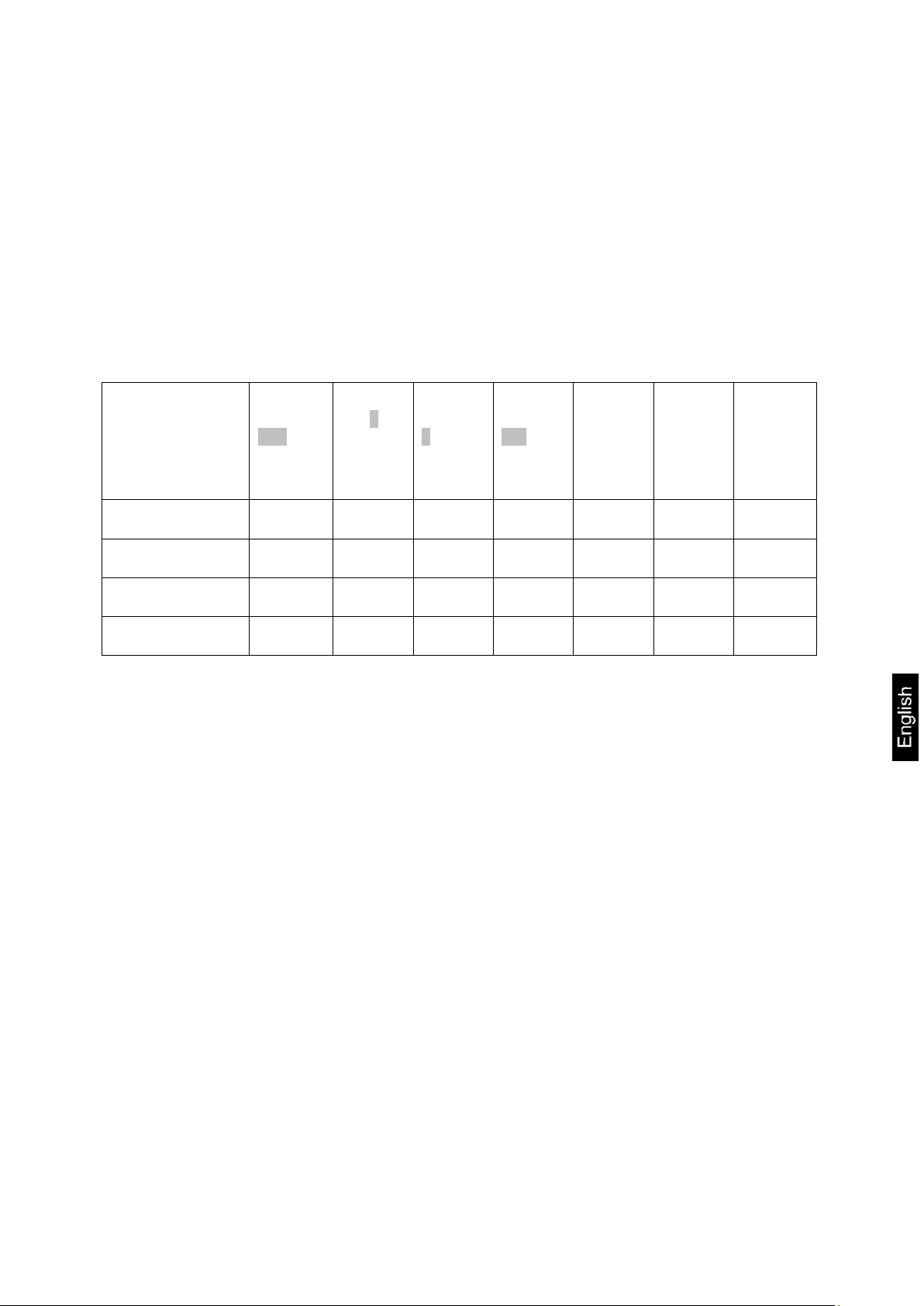
1 General hints
Model
Weighing
range
Max
Readabil
ity d
Verificati
on value
e
Minimum
load
Min
Preload
additive
Cable
length
approx.
Net
weight
approx.
kg g g kg kg m kg
KFD 600V40M
600
200
200
4
120
5
131
KFD 600V40LM
600
200
200
4
120
5
175
KFD 1500V40M
1500
500
500
10
300
5
131
KFD 1500V40LM
1500
500
500
10
300
5
175
These installation instructions contain all data necessary for placing and
commissioning the following weighing bridges:
KERN KFD 600V40M
KERN KFD 600V40LM
KERN KFD 1500V40M
KERN KFD 1500V40LM
2 Technical data
KFD V40-IA-e-1310 3
Page 4
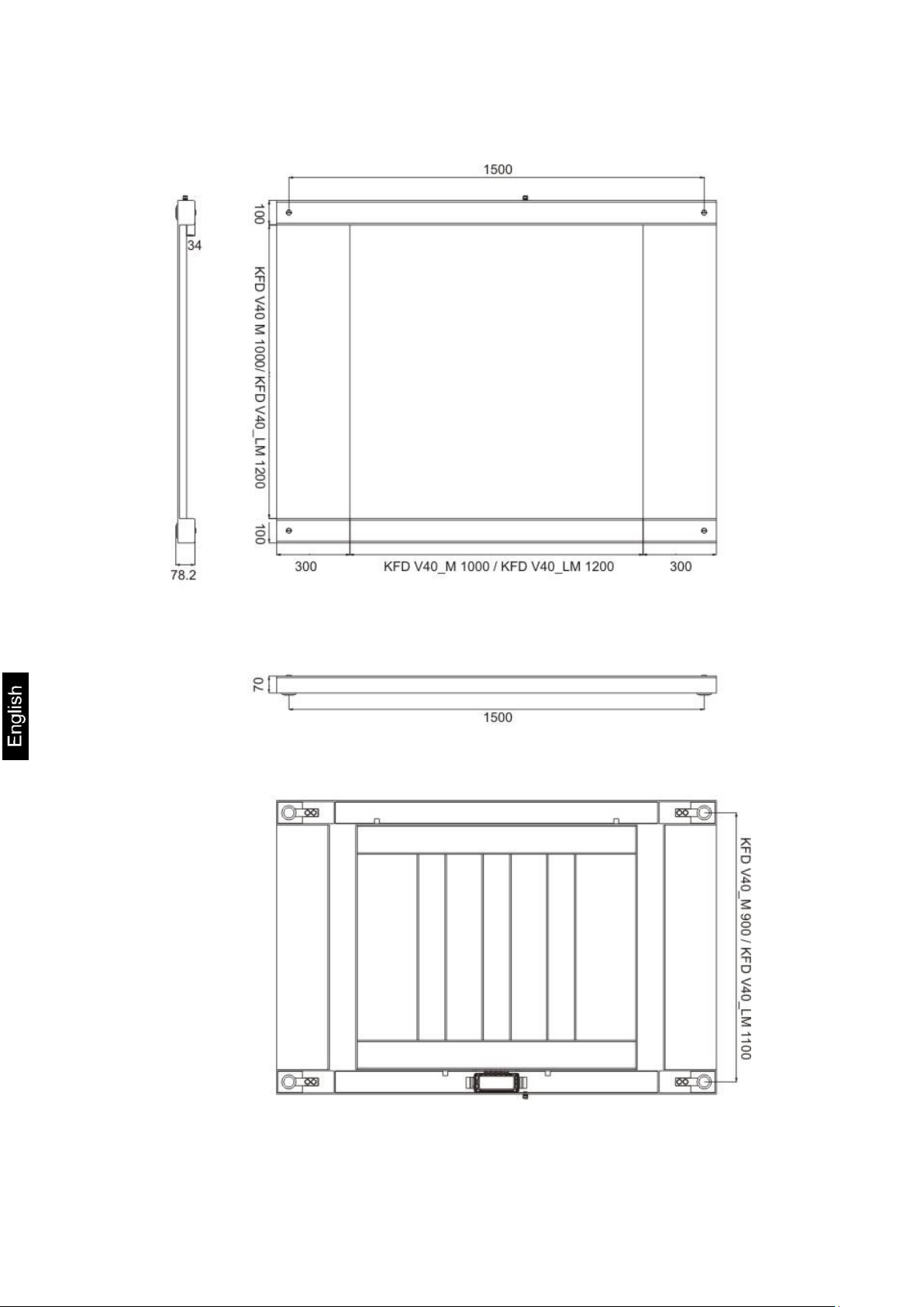
2.1 Dimensions
4 KFD V40-IA-e-1310
Page 5
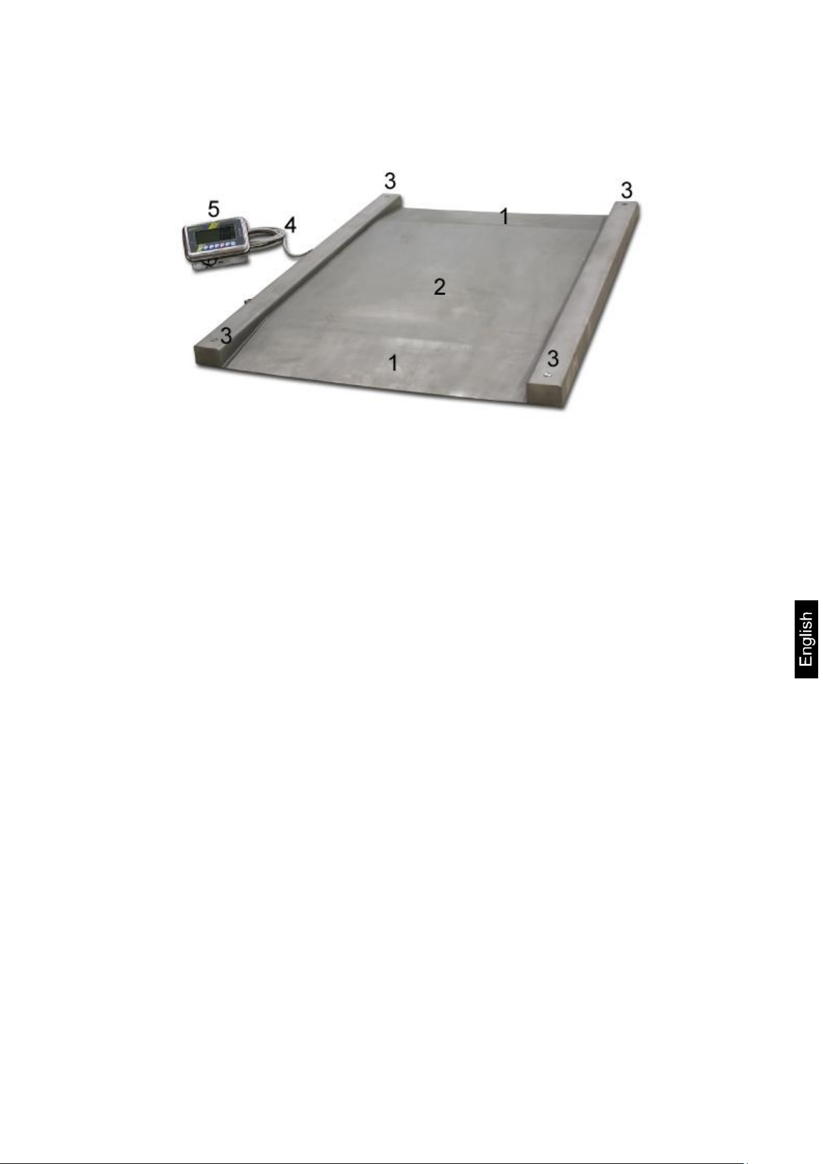
3 Appliance overview
1
Access ramp
2
Weighing bridge
3
Cover of weighing cell feet
4
Connection cable
5
Display Unit
KFD V40-IA-e-1310 5
Page 6
4 Basic Information (General)
4.1 Documentation
These installation instructions contain all data necessary for placing and
commissioning the weighing bridges KERN KFD V40.
In combination with a display unit, described below as weighing system, for operation
configuration, please refer to the operating instructions of the display unit.
4.2 Proper use
The balance you purchased is intended to determine the weighing value of material
to be weighed. It is intended to be used as a “non-automatic balance”, i.e. the
material to be weighed is manually and carefully placed in the centre of the weighing
pan.. As soon as a stable weighing value is reached the weighing value can be read.
4.3 Improper Use
Do not leave permanent load on the weighing bridge. This may damage the
measuring system.
Impacts and overloading exceeding the stated maximum load (max) of the weighing
system, minus a possibly existing tare load, must be strictly avoided. The weighing
system could be damaged.
Never operate in an explosive environment. The serial version is not explosion
protected.
Changes to the weighing system's design are not permitted. This may lead to
incorrect weighing results, safety-related faults and destruction of the balance.
The weighing system unit may only be operated in accordance with the described
default settings. Other areas of use must be released by KERN in writing.
4.4 Warranty
Warranty claims shall be voided in case
Our conditions in the operation manual are ignored
The appliance is used outside the described uses
Structural changes of the device
Mechanical damage and damage caused by media, liquids
Natural wear and tear
The appliance is improperly set up or incorrectly electrically connected
Overload of the measuring system
6 KFD V40-IA-e-1310
Page 7

4.5 Monitoring of Test Resources
Carefully read this operation manual before setup and commissioning,
even if you are already familiar with KERN balances.
All language versions contain a non-binding translation.
The original German is binding.
Keep all parts of the original packaging for a possibly
required return.
Only use original packaging for returning.
Prior to dispatch disconnect all cables and remove
loose/mobile parts.
Reattach possibly supplied transport securing devices.
Secure all parts against shifting and damage.
In the framework of quality assurance the measuring-related properties of the
weighing system and, if applicable, the testing weight, must be checked regularly.
The responsible user must define a suitable interval as well as type and scope of this
test. Information is available on KERN’s home page (www.kern-sohn.com) with
regard to the monitoring of weighing system test substances and the test weights
required for this. In KERN's accredited DKD calibration laboratory test weights and
weighing systems may be calibrated (return to the national standard) fast and at
moderate cost.
5 Basic Safety Precautions
5.1 Pay attention to the instructions in the Operation Manual
5.2 Personnel training
The appliance may only be operated and maintained by trained personnel.
The installation of a display unit must only be carried out by a well acquainted
specialist with the workings of weighing balances.
6 Transport and storage
6.1 Testing upon acceptance
When receiving the appliance, please check packaging immediately, and the
appliance itself when unpacking for possible visible damage.
6.2 Packaging / return transport
KFD V40-IA-e-1310 7
Page 8
7 Unpacking, Setup and Commissioning
7.1 Installation Site, Location of Use
The weighing bridges are designed in a way that reliable weighing results are
achieved in common conditions of use.
You will work accurately and fast, if you select the right location for your weighing
system.
On the installation site observe the following:
Place the weighing system on a firm, level surface.
The floor at the installation site must be able to carry safely the weight of the
maximally loaded weighing bridge at the resting points. At the same time it
should be sufficiently stable, that no vibrations may occur during weighing
work.
In the installation site possibly no vibrations, e.g. by neighbouring machines
should occur.
Do not use the weighing bridge in an explosive environment.
Avoid extreme heat as well as temperature fluctuation caused by installing
next to a radiator or in the direct sunlight.
Protect the weighing bridge against direct draughts e.g. due to open windows
and doors.
Use weighing bridge only in dry environment, protect it against high humidity,
vapours and dust.
Do not expose the device to extreme dampness for longer periods of time.
Non-permitted condensation (condensation of air humidity on the appliance)
may occur if a cold appliance is taken to a considerably warmer environment.
In this case, acclimatize the disconnected appliance for ca. 2 hours at room
temperature.
Avoid jarring during weighing.
Avoid static charge of goods to be weighed or weighing container.
Keep away chemicals (such as liquids or gasses), which could attack and
damage the balance inside or from outside.
Keep IP protection of the device.
Major display deviations (incorrect weighing results) may be experienced
should electromagnetic fields (e.g. due to mobile phones or radio equipment),
static electricity accumulations or instable power supply occur. Change
location or remove source of interference.
8 KFD V40-IA-e-1310
Page 9

7.2 Unpacking, Scope of delivery
CAUTION
+ Danger for the back!
The weighing bridge is relatively heavy. Always use a suitable
lifting device to lift it out of the packaging or to transport it to
the required installation site.
+ Do not step under the suspended load, risk of injury!
+ The weighing bridge must be aligned with the help of a
water level.
+ All setting feet must rest equally.
Verified weighing systems:
In case of verified weighing systems the weighing bridge must be
firmly fixed on the floor. This is essential for the reproducibility of
the measuring results and may be replaced with the help of foot
plate pairs.
Remove outer packaging and packaging material.
Lift the weighing bridge equally off the packaging material, see caution note.
Secure the weighing bridge that it cannot fall down when it is lifted.
Ensure that the contents of package is complete.
Scope of delivery:
Weighing bridge see chapter 3
Operating manual
7.3 Assembly, levelling
Accurate weighing results require a weighing bridge with perfect horizontal
alignment. During initial installation and after each change of work area it is
necessary to level the weighing bridge.
Prior to the final placing, install the four weighing cell feet.
Place the weighing bridge equally on the installation site and check if it is in an
even position and all four feet are in contact with the floor. Level the weighing
bridge by turning the weighing cell feet. For this purpose use an external
levelling appliance, e.g. a water level.
Ensure that the connecting cable is not damaged or squeezed during lifting and
placing.
KFD V40-IA-e-1310 9
Page 10
7.4 Connecting a display unit
Terminal
Color
State
EXC+ [IN+]
red
voltage +
SIG + [OUT+]
green
signal +
SIG -[OUT-]
white
signal -
EXC -[IN- ]
black
voltage -
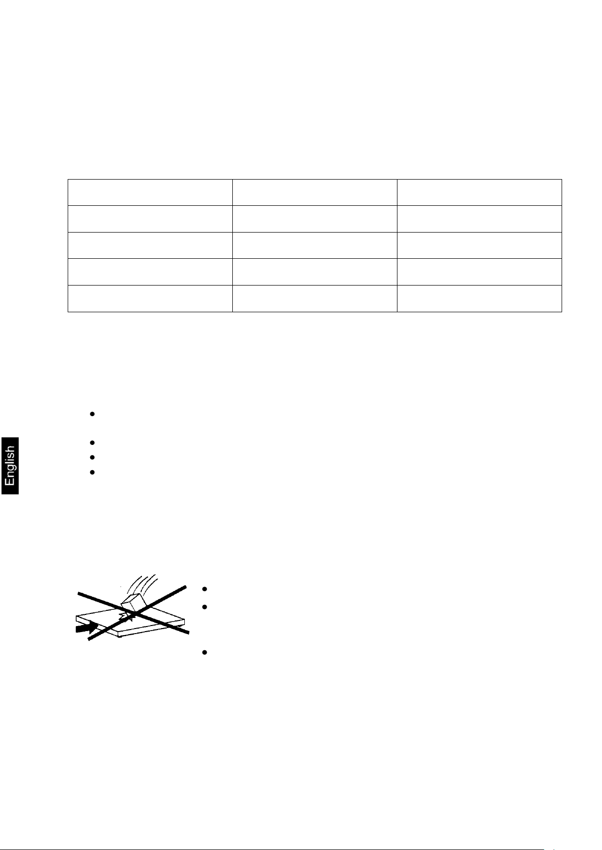
So a continuous optimal performance is guaranteed:
Avoid falling load, shock loads and impacts from the side!
For weighing operation, all objects must be placed
centrically of the weighing bridge and may not hang over
the edges or the ramps.
Check adjustment at regular intervals.
Attention
Put the connecting cable to the display unit in a manner that it is protected against
damage.
Description of the connection cable:
8 Operation
Information about
Network connection (power is supplied via the connecting cable of the
display unit)
Initial Commissioning
Connection of peripheral devices
Adjustment, linearization and verification (only the complete balance is
verifiable, i.e. weighing bridge in conjunction with a suitable display unit)
and the correct operation you will in the operating instructions included in the scope
of delivery of the display unit.
10 KFD V40-IA-e-1310
Page 11

8.1 Operation limits
Weighing ranges
600kg
1500kg
With centrical load
3000kg
4500kg
With side stress
2000kg
3000kg
With one-sided loading
1000kg
1500kg
With single-wheel load
400kg
800kg
The weighing bridges are designed extremely robust. However the load limits
according to the following table should not be exceeded!
Depending on the type of load receptacle, the static carrying capacity, i.e. the
maximum admissible load is:
8.2 Load/unload weighing bridge
Place the load on the scales using a lifting truck, a crane or a forklift truck. Ensure
that the load is not swinging when it is placed onto the scales.
Lift the load first vertically at least 10 cm above the scales before it is removed or
newly placed.
KFD V40-IA-e-1310 11
Page 12
9 Servicing, maintenance, disposal
Before any maintenance, cleaning and repair work disconnect the
appliance from the operating voltage.
9.1 Daily check
Ensure that all four feet are in contact with the floor.
Ensure that the connecting cable to the display unit and the network connection
cable of the display unit are not damaged.
Ensure that the balance is free from dirt, especially under the edges of the
balance.
9.2 Cleaning
Clean the stainless-steel parts with a soft cloth soaked with a cleaning agent
suitable for stainless steel.
For stainless steel parts do not use any cleaning agents which contain sodium
hydroxide solution, acetic, hydrochloric, sulphuric or citric acid.
Do not use metal brushes or cleaning sponges of steel wool, as this causes
superficial corrosion.
Take away the weighing plate and remove dirt and foreign matters, which have
been accumulated below. Do not use hard or sharp objects for this.
Remove regularly corrosive substances.
9.3 Comply with the IP protection Maintenance, servicing
The appliance may only be opened by trained service technicians who are
authorized by KERN.
Ensure that the weighing system is regularly calibrated, see chap. 4.5 Testing
instruments control.
9.4 Disposal
Disposal of packaging and appliance must be carried out by operator according to
valid national or regional law of the location where the appliance is used.
12 KFD V40-IA-e-1310
Page 13

9.5 Instant help
Fault
Possible cause
The displayed weight is permanently
changing
Draught/air movement
Floor vibrations
Weighing plate has contact with other
objects.
Electromagnetic fields / static charging
(choose different location/switch off
interfering device if possible)
The weighing result is obviously
incorrect
No zero display with unloaded balance
Adjustment is no longer correct.
Great fluctuations in temperature.
Weighing bridge on an uneven surface.
Electromagnetic fields / static charging
(choose different location/switch off
interfering device if possible)
In case of an error in the program process, briefly turn off the balance and disconnect
from power supply. The weighing process must then be restarted from the beginning.
Help:
Should other error messages occur, switch balance off and then on again. If the error
message remains inform manufacturer.
KFD V40-IA-e-1310 13
Page 14

10 Service documentation
This chapter is only intended for a balance specialist!
At every each corner of the weighing bridge a DMS weighing cell is
installed.
The analogue-digital transformation occurs in the display unit. Also all
the balance and country-specific data are stored there.
Capacity
600 kg
1500 kg
Readability
200 g
500 g
Min
4 kg
10 kg
Max
600 kg
1500 kg
1/3 corner load
200 kg
500 kg
Tolerance
200 g
500 g
10.1 Overview, setting regulation, tolerances
Testing and setting regulations:
14 KFD V40-IA-e-1310
Page 15

Verification data and tolerances as per OIML
-1
-0,75
-0,5
-0,25
0
0,25
0,5
0,75
1
0 500 1000 1500
[kg]
[g]
-0,4
-0,3
-0,2
-0,1
0
0,1
0,2
0,3
0,4
0 100 200 300 400 500 600
[kg]
[g]
600kg
1500kg
KFD V40-IA-e-1310 15
Page 16

10.2 Check and adjustment of the corner load
Check of the corner load:
Place the test weights in the centre of the load plate
and tare.
The balance displays -0-.
Place the test weights successively on all four
corners.
Now the deviations are displayed with sign, write
down the values. If there are deviations out of the
tolerances (see chap. 9.1), an adjustment will be
necessary.
Adjustment of corner load:
Preparation:
For a better control of the modifications which occur
during adjustment, select in the configuration menu
the highest readability for control purposes.
Open connection box
Adjustment rule:
The corner (weighing cell) with the biggest negative
deviation must be set to zero. Do not re-adjust this corner
even after several adjustment sequences.
16 KFD V40-IA-e-1310
Page 17
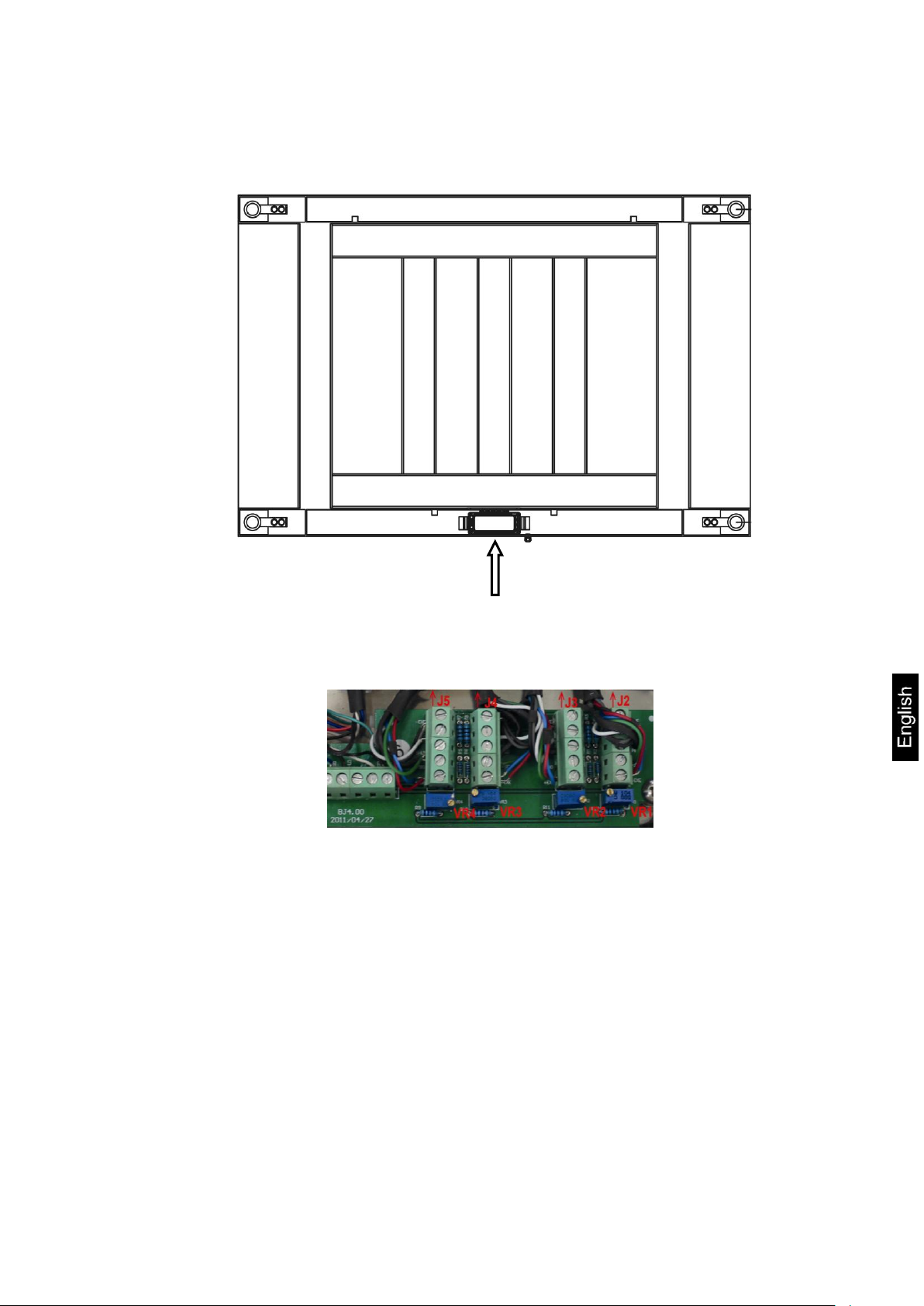
Adjustment on the analogue print
Adjustment of weighing cell J2 takes place at potentiometer VR1.
Adjustment of weighing cell J3 takes place at potentiometer VR2.
Adjustment of weighing cell J4 takes place at potentiometer VR3.
Adjustment of weighing cell J5 takes place at potentiometer VR4.
Increase the value turning to the right, reduce the value turning to the left.
KFD V40-IA-e-1310 17
Page 18
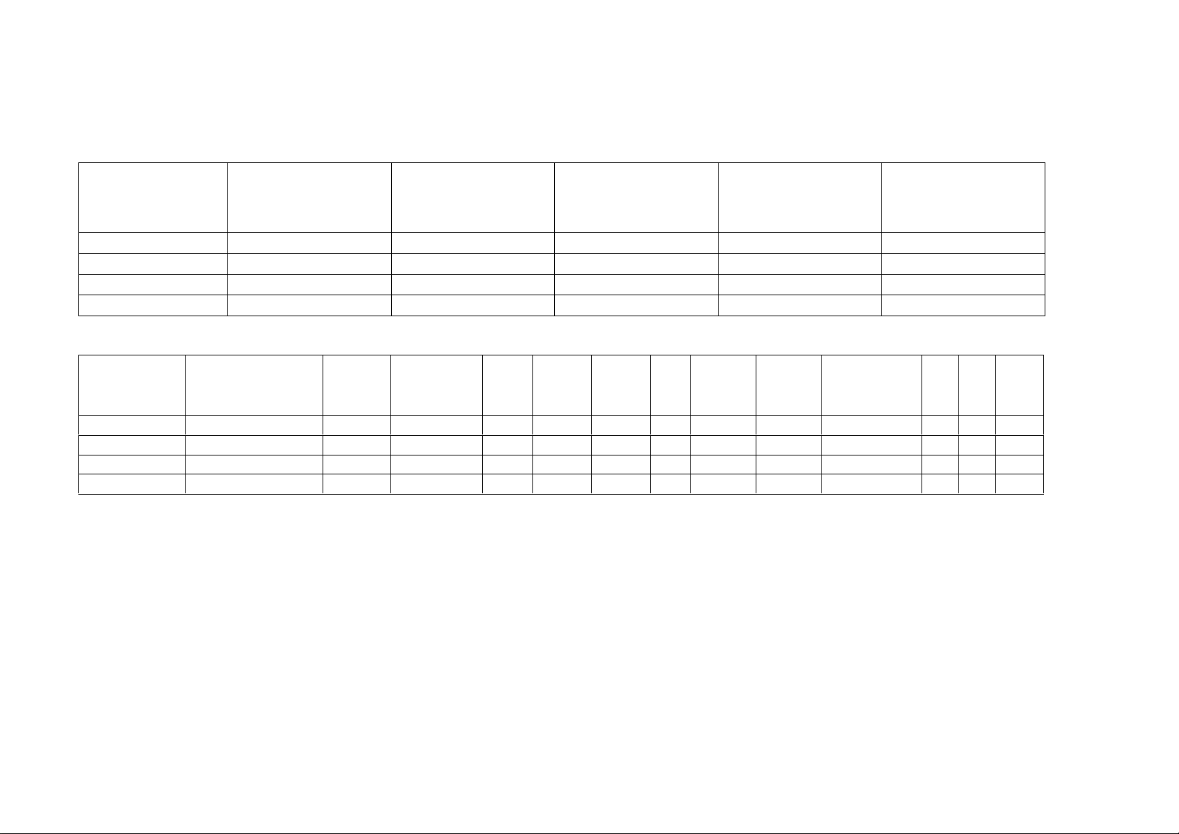
Kern model
max. Preload* (kg)
* = additive preload
Deadload** (kg)
**= already applied
preload
Center Overload
Protection circa (kg)
Corner Overload
Protection circa (kg)
Loadcell
Capacity (kg)
KFD 600V40M
0
100kg
0
0
500 kg
KFD 600V40LM
0
160kg
0
0
500 kg
KFD 1500V40M
0
100kg
0
0
1000 kg
KFD 1500V40LM
0
160kg
0
0
1000 kg
Platform type
Platform dimension
(mm)
Loadcell
TC
Class
Max
E
max
E
min
Y
n
Dead-load
T
min
T
max
Cable-
Type
Nr.
Preload
-1
-4 -3
(kg)
-5 -6
length
(kg)
(kg)
(g)
(m)
KFD 600V40M
1000x1000
H8C
D09-03.19R2
C3 0 500kg
30
15000
3000
100kg
-10
40
5
KFD 600V40LM
1200x1200
H8C
D09-03.19R2
C3 0 500kg
30
15000
3000
160kg
-10
40
5
KFD 1500V40M
1000x1000
SQB
TC6911
C3
0
1000kg
100
10000
3000
100kg
-10
40 5 KFD 1500V40LM
1200x1200
SQB
TC6911
C3
0
1000kg
100
10000
3000
160kg
-10
40
5
11 Preload, Deadload and Overload settings
18 KFD V40-IA-e-1211
 Loading...