

Page 1
KERN & Sohn GmbH
Ziegelei 1
D-72336 Balingen
E-Mail: info@kern-sohn.com
Phone: +49-[0]7433- 9933-0
Fax: +49-[0]7433-9933-149
Internet: www.kern-sohn.com
Installation Instructions
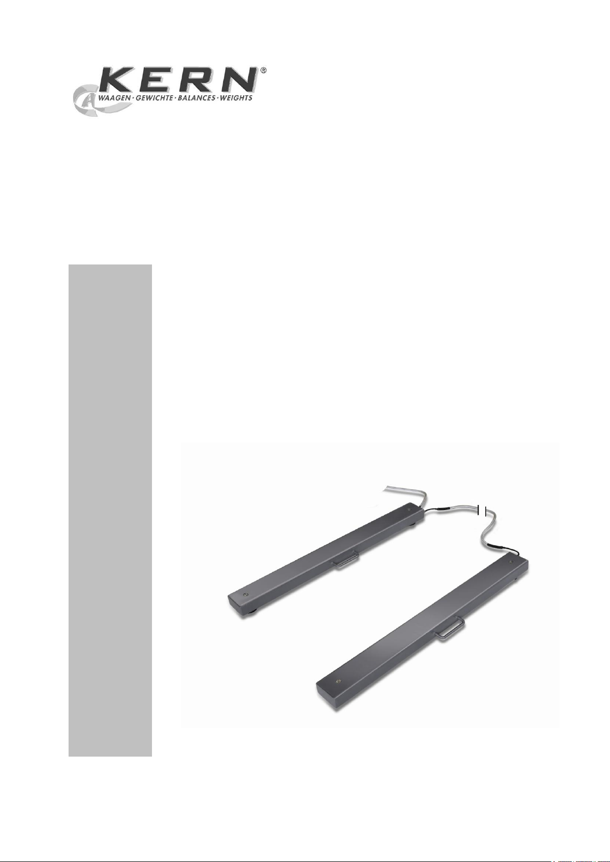
Weighing beams
KERN KFA V20
Version 1.2
08/2013
GB
KFA V20-IA-e-1312
Page 2
GB
KERN KFA V20
Version 1.2 08/2013
Installation Instructions Weighing beams
Contents
1 Technical data ................................................................................................ 3
2 Appliance overview ....................................................................................... 5
3 Basic Information (General) .......................................................................... 6
3.1 Documentation ........................................................................................................................... 6
3.2 Proper use .................................................................................................................................. 6
3.3 Improper Use .............................................................................................................................. 6
3.4 Warranty ..................................................................................................................................... 6
3.5 Monitoring of Test Resources ..................................................................................................... 7
4 Basic Safety Precautions .............................................................................. 7
4.1 Pay attention to the instructions in the Operation Manual .......................................................... 7
4.2 Personnel training ....................................................................................................................... 7
5 Transport and storage ................................................................................... 7
5.1 Testing upon acceptance ........................................................................................................... 7
5.2 Packaging / return transport ....................................................................................................... 7
6 Unpacking, Setup and Commissioning ....................................................... 8
6.1 Installation Site, Location of Use ................................................................................................ 8
6.2 Unpacking and placing ............................................................................................................... 9
6.3 Connecting a display screen ..................................................................................................... 10
7 Operation ................................................................ ................................ ...... 10
7.1 Load/unload weighing beams ................................................................................................... 11
8 Service, maintenance, disposal .................................................................. 12
8.1 Daily check ............................................................................................................................... 12
8.2 Cleaning .................................................................................................................................... 12
8.3 Service, maintenance ............................................................................................................... 12
8.4 Disposal .................................................................................................................................... 12
8.5 Instant help ............................................................................................................................... 13
9 Service documentation ............................................................................... 14
9.1 Overview, setting regulation, tolerances ................................................................................... 14
9.2 Check and adjustment of the corner load ................................................................................. 15
10 Preload / Deadload settings ........................................................................ 16
2 KFA V20-IA-e-1312
Page 3
1 Technical data
Model
Weighing
range
Max
Readability
d
Preload
additive
Cable length
display
screen
approx.
Connecting
cable
weighing
beams
approx.
Net weight
approx.
kg
kg
kg m m
kg
KFA 1500V20
1500
0.5
300 5 2.5
42
KFA 3000V20
3000
1
500 5 2.5
42
KFA
3000V20L
3000
1
500 5 1.5
42
KFA 6000V20
6000
2
1000
5
1.5
35
KFA
6000V20L
6000
2
1000
5
1.5
42
KFA V20-IA-e-1312 3
Page 4
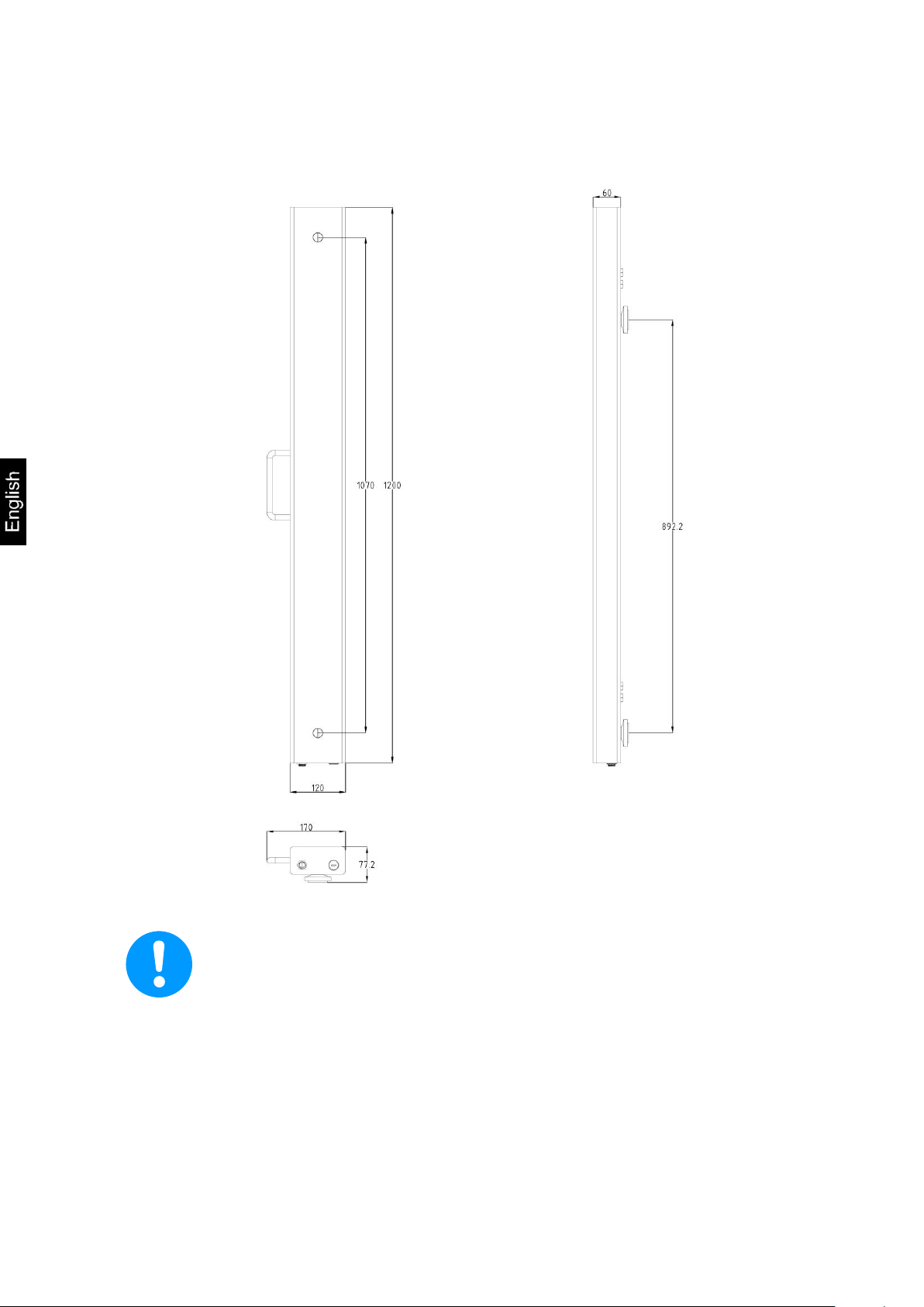
„L“-models length 2000 mm
Dimensions:
4 KFA V20-IA-e-1312
Page 5
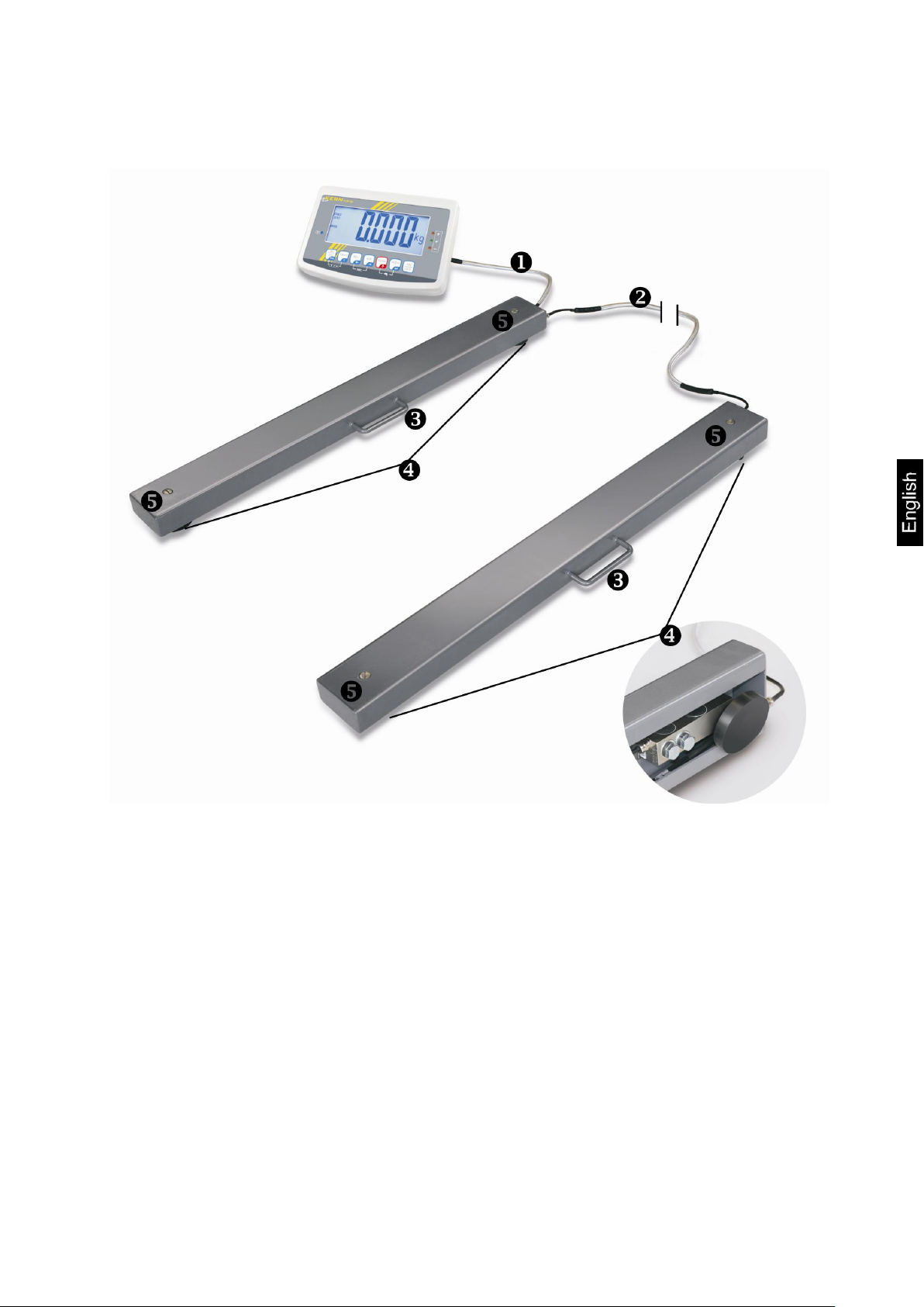
2 Appliance overview
Mains lead display screen
Connecting cable weighing beams
Handle for easy transport
Weighing cell feet and weighing cells
Cover adjusting screw for weighing cell feet
Illustrative example weighing system KERN KFA V20 + KFB-TM
KFA V20-IA-e-1312 5
Page 6
3 Basic Information (General)
3.1 Documentation
These installation instruction contain all data necessary for placing and
commissioning the weighing beams KERN KFA V20.
In combination with a display unit, described below as weighing system, for operation
configuration, please refer to the operating instructions of the display unit.
3.2 Proper use
The weighing beams are designed for weighing of large, voluminous or long loads.
They are designed to be used as “non-automatic scales“ As soon as a stable
weighing value is reached the weighing value can be read.
3.3 Improper Use
Do not leave loads permanently on the weighing beams. This may damage the
measuring system.
Impacts and overloading exceeding the stated maximum load (max) of the weighing
beams, minus a possibly existing tare load, must be strictly avoided. This may
damage the weighing beams.
Never operate in an explosive environment. The serial version is not explosion
protected.
Do not modify the construction of the weighing beams. This may lead to incorrect
weighing results, safety-related faults and destruction of the weighing beams.
The weighing beams may only be used according to the described conditions. Other
areas of use must be released by KERN in writing.
3.4 Warranty
Warranty claims shall be voided in case
Our conditions in the operation manual are ignored
The appliance is used outside the described uses
Structural changes of the device
Mechanical damage and damage caused by media, liquids
Natural wear and tear
The appliance is improperly set up or incorrectly electrically connected
Overload of the measuring system
6 KFA V20-IA-e-1312
Page 7

3.5 Monitoring of Test Resources
Carefully read this operation manual before setup and commissioning,
even if you are already familiar with KERN balances.
Versions in other languages are non-binding translations.
The only binding version is the original document in German.
Keep all parts of the original packaging for a possibly
required return.
Only use original packaging for returning.
Prior to dispatch disconnect all cables and remove
loose/mobile parts.
Reattach possibly supplied transport securing devices.
Secure all parts against shifting and damage.
In the framework of quality assurance the measuring-related properties of the
weighing system and, if applicable, the testing weight, must be checked regularly.
The responsible user must define a suitable interval as well as type and scope of this
test. Information is available on KERN’s home page (www.kern-sohn.com with
regard to the monitoring of weighing system test substances and the test weights
required for this. In KERN's accredited DKD calibration laboratory test weights and
weighing systems may be calibrated (return to the national standard) fast and at
moderate cost.
4 Basic Safety Precautions
4.1 Pay attention to the instructions in the Operation Manual
4.2 Personnel training
The appliance may only be operated and maintained by trained personnel.
The installation of a display unit must only be carried out by a well acquainted
specialist with the workings of weighing balances.
5 Transport and storage
5.1 Testing upon acceptance
When receiving the appliance, please check packaging immediately, and the
appliance itself when unpacking for possible visible damage.
5.2 Packaging / return transport
KFA V20-IA-e-1312 7
Page 8

6 Unpacking, Setup and Commissioning
6.1 Installation Site, Location of Use
The weighing beams are designed in a way that reliable weighing results are
achieved in common conditions of use.
To enable exact and fast work, select the right site.
On the installation site observe the following:
Place the weigh beam on a level and stable surface.
The foundations at the site must be able to bear the weight of the weighing
beams as well as the weight of the maximum weight.
Avoid extreme heat as well as temperature fluctuation caused by installing
next to a radiator or in the direct sunlight
Protect the weighing system against direct draughts due to open windows and
doors
Avoid jarring during weighing
Protect the weighing beams against high humidity, vapours and dust
Do not expose weighing beams to moisture over a long period of time. Non-
permitted condensation (condensation of air humidity on the appliance) may
occur if a cold appliance is taken to a considerably warmer environment. In
this case, acclimatize the disconnected appliance for ca. 2 hours at room
temperature
Avoid static charge of goods to be weighed or weighing container
Do not lean weighing beams against a wall
Do not move weighing beams whilst loaded
Keep away chemicals (such as liquids or gasses), which could attack and
damage the weighing beams inside or from outside
Keep IP protection of the device
Major display deviations (incorrect weighing results) may be experienced should
electromagnetic fields (e.g. due to mobile phones or radio equipment), static
electricity accumulations or instable power supply occur. Change location or remove
source of interference.
8 KFA V20-IA-e-1312
Page 9

6.2 Unpacking and placing
Unpacking:
Remove weighing beams and accessories carefully from packaging, remove
packaging material and place device at the planned work place. Verify that there has
been no damage and that all packing items are present.
Scope of delivery:
2 Weighing beams with fitted “mains lead display screen“ and “connecting cable
weighing beams”.
4 weighing cell feet
Operating instructions
Placing:
Prior to the final placing, install the four weighing cell feet.
Ensure a level surface on the installation site, particularly around the weighing
cell feet.
Put down the weighing beams and check whether they are positioned level and
that all four feet reach the floor. Adjust minor height differences by adjusting the
weighing cell feet.
For this purpose remove the cap head screw (See chapter 2, item ) and adjust
the height of the 4 weighing cells by turning the adjusting screw. For this purpose
use an external levelling appliance, e.g. a water level.
Make sure not to crimp or damage the mains lead and connecting cable when
lifting or placing.
KFA V20-IA-e-1312 9
Page 10

6.3 Connecting a display screen
terminal
Color
State
EXC+ [IN+]
red
voltage +
SIG + [OUT+]
green
signal +
SIG -[OUT-]
white
signal -
EXC -[IN- ]
black
voltage -
Attention
Put the connecting cable to the display unit in a manner that it is protected against
damage.
Description of the connection cable:
7 Operation
Information about
Network connection
Power is supplied via the connecting cable of the display unit
Initial Commissioning
Connection of peripheral devices
and the correct operation you will in the operating instructions included in the scope
of delivery of the display unit.
10 KFA V20-IA-e-1312
Page 11

7.1 Load/unload weighing beams
The weighing beams are designed for an evenly spread load
Avoid falling load, shock loads and impacts from the side.
Weighing beams must not be moved when loaded.
Place the load onto both weighing beams by using a pallet truck, crane or fork lift.
Ensure that the load is not swinging when it is placed onto the weighing beams.
Lift the load first vertically at least 10 cm above the weighing beams before it is
removed or newly placed.
KFA V20-IA-e-1312 11
Page 12

8 Service, maintenance, disposal
Before any maintenance, cleaning and repair work disconnect the
appliance from the operating voltage.
8.1 Daily check
Ensure that all four feet are in contact with the floor.
Ensure that cables are not damaged.
Ensure that the weighing beams are free of soiling, in particular underneath the
edges.
8.2 Cleaning
! Remove regularly corrosive substances.
! Keep IP protection.
! Do not aim water or steam jet at the weigh cells.
Clean weighing beams using a soft cloth soaked in a mild detergent. Take care
that the device is not penetrated by fluids and polish it with a dry soft cloth.
8.3 Service, maintenance
The appliance may only be opened by trained service technicians who are
authorized by KERN.
Ensure that the weighing system is regularly calibrated, see chap. 3.5 Testing
instruments control.
8.4 Disposal
Disposal of packaging and appliance must be carried out by operator according
to valid national or regional law of the location where the appliance is used.
12 KFA V20-IA-e-1312
Page 13

8.5 Instant help
Fault
Possible cause
The displayed weight is permanently
changing
Draught/air movement
Floor vibrations
Weighing beams come into contact with
foreign substances.
Electromagnetic fields / static charging
(choose different location/switch off
interfering device if possible)
The weighing result is obviously
incorrect
No zero display for unloaded weighing
beams.
Adjustment is no longer correct.
Great fluctuations in temperature.
The weighing beams are not level.
Electromagnetic fields / static charging
(choose different location/switch off
interfering device if possible)
In case of an error in the program process, briefly turn off the weighing system and
disconnect from power supply. The weighing process must then be restarted from
the beginning.
Help:
Should other error messages occur, switch balance off and then on again. If the error
message remains inform manufacturer.
KFA V20-IA-e-1312 13
Page 14

9 Service documentation
This chapter is only intended for a balance specialist!
The weighing beams are fitted with a DMS weigh cell at each corner.
The analogue-digital transformation occurs in the display unit. Also all
the balance and country-specific data are stored there.
Capacity
600 kg
1500 kg
Readability
200 g
500 g
Min
4 kg
10 kg
Max
600 kg
1500 kg
1/3 corner load
200 kg
500 kg
Tolerance
200 g
500 g
-1
-0,75
-0,5
-0,25
0
0,25
0,5
0,75
1
0 500 1000 1500
[kg]
[g]
-0,4
-0,3
-0,2
-0,1
0
0,1
0,2
0,3
0,4
0 100 200 300 400 500 600
[kg]
[g]
600kg
1500kg
9.1 Overview, setting regulation, tolerances
Testing and setting regulations:
Verification data and tolerances as per OIML:
14 KFA V20-IA-e-1312
Page 15

9.2 Check and adjustment of the corner load
Check of the corner load:
Place a suitable aid such as a pallet on both weighing
beams. Make sure that the aid is designed to bear
the weight of the test weight.
Place the test weights in the centre of the load plate
and tare.
The balance displays -0-.
Place the test weights successively on all four
corners.
Now the deviations are displayed with sign, write
down the values. If there are deviations out of the
tolerances (see chap. 9.1), an adjustment will be
necessary.
Adjustment of corner load:
Preparation:
For a better control of the modifications which occur
during adjustment, select in the configuration menu
the highest readability for control purposes.
Open connection box
Adjustment rule:
The corner (weighing cell) with the biggest negative
deviation must be set to zero. Do not re-adjust this
corner even after several adjustment sequences.
Adjustment on the analogue print
Adjustment of weighing cell J2 takes place at the potentiometer VR1.
Adjustment of weighing cell J3 takes place at the potentiometer VR2.
Adjustment of weighing cell J4 takes place at the potentiometer VR3.
Adjustment of weighing cell J5 takes place at the potentiometer VR4.
Increase the value turning to the right, reduce the value turning to the left.
KFA V20-IA-e-1312 15
Page 16

Kern model
Max. preload* (kg)
* = additive preload
Deadload** (kg)
**= already applied
preload
Center Overload
Protection circa
(kg)
Corner Overload
Protection circa
(kg)
Loadcell
Capacity (kg)
KFA 1500V20
0
39
NA
NA
1000kg
KFA 3000V20
0
39
NA
NA
1500kg
KFA 3000V20L
0
55
NA
NA
1500kg
KFA 6000V20
0
85
NA
NA
3000kg
KFA 6000V20L
0
95
NA
NA
3000kg
Platform
type
Platform
dimension
(mm)
Load
cell
TC
Class
Max
E
max
E
mi
n
Y
n
Deadload
T
min
T
max
Type
No.
Pre
load
-1
-4 -3
(kg) -5 -6
(kg)
(kg)
(g)
KFA 1500V20
1200x120
SQB
TC6911
C3 0 1000
0
10000
3000
36
-10
40
KFA 3000V20
1200x120
SQB
TC6911
C3 0 1500
0
10000
3000
36
-10
40
KFA 3000V20L
2000x120
SQB
TC6911
C3 0 1500
0
10000
3000
55
-10
40
KFA 6000V20
1200x120
SQB
TC6911
C3 0 3000
0
10000
3000
85
-10
40
KFA 6000V20L
2000x120
SQB
TC6911
C3 0 3000
0
10000
3000
95
-10
40
10 Preload / Deadload settings
16 KFA V20-IA-e-1312
 Loading...