

Page 1
Sauter GmbH
Ziegelei 1
D-72336 Balingen
E-Mail: info@sauter.eu
Tel: +49-[0]7433- 9933-199
Fax: +49-[0]7433-9933-149
Internet: www.kern-sohn.com
Instruction Manual
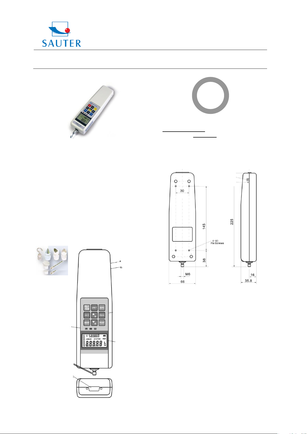
FH
Sensor
Inside
Adaptersockel
Re Set Taste
Set
LCD
Grenzwert
Anzeige
RS 232
Kraftaufnehmer
Power plug
Reset button
Se
Display
Pilot lamp
RS-232 port
Force Sensor
Thank you for buying a SAUTER force gauge. We hope
you are pleased with your high quality force gauge with its
big functional range. If you have any queries, wishes or
helpful suggestions, do not hesitate to call our service
number.
„Sensor Inside“ means the measuring cell is inside the
housing.
1. Included in delivery
- SAUTER FH incl. rechargeable battery
- Carrying Case
- Charger
- Standard Attachments as shown below,
5 pcs M3 x 8 screws
Important annotation:
By pressing the RESET key (on the right side of housing,
see illustration on the left), individual settings and
memorised values can be re-set or erased, in example for
a new start of the instrument after an operating error.
Data in mm
FH_SI-BA-e-1317 1
2. Working Conditions
10°C to 30°C / 15% up to 80% humidity
3. Electrical Power Supply
Either by rechargeable battery or current power supply
Current power supply:
- Connection by power adapter
- Rechargeable batteries are charged
simultaneously
Rechargeable battery pack for mobile applications:
- Type: Ni 8.4V / 600 mAh
- Charging time: approx. 1 hour
Page 2
Sauter GmbH
Ziegelei 1
D-72336 Balingen
E-Mail: info@sauter.eu
Tel: +49-[0]7433- 9933-199
Fax: +49-[0]7433-9933-149
Internet: www.kern-sohn.com
Instruction Manual
FH
Hi Lt
Lo dT
Lo Pe
P.OFF
HoldT
rS232
StoP
4. Technical Data
- Accuracy: ± 0,5 % of Capacity (measuring range)
- Data Sampling Rate: 2.000 Hz
- Weight: 640 g
5. Operation
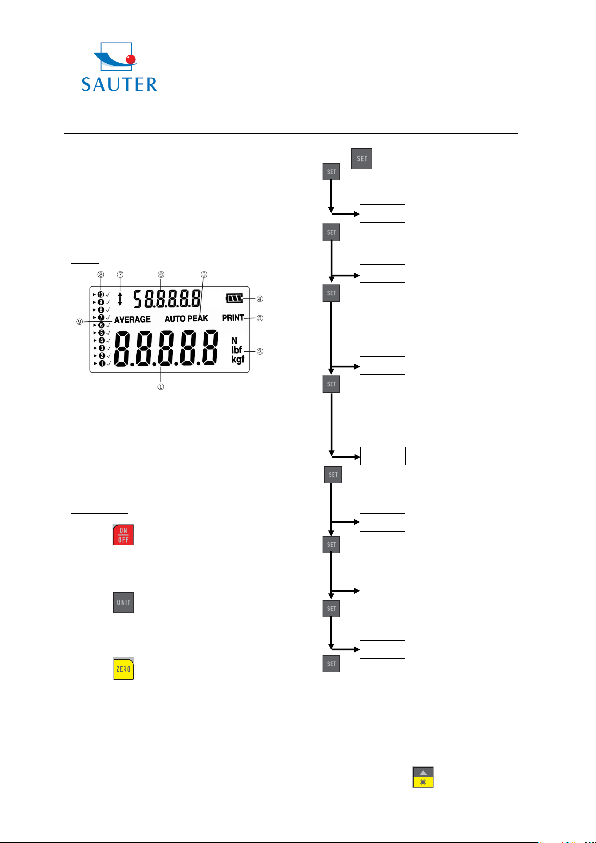
Display
(1) Measuring Result
(2) Measuring Units
(3) Activation of PRINT Function
(4) Indication of power charging status
(5) PEAK or AUTO-PEAK Mode
(6) Average value of stored peak values
(7) Force direction
(8) Occupancy of storing spaces
(9) AVERAGE- or Saving Mode
Operation keys
ON / OFF:
ON / OFF key
(For ON, press 1 sec.)
UNIT:
- Press shortly: Select unit:
- Press for 2 sec.: Display return
ZERO:
Three functions:
- Zeros the measuring result (Tara function)
- Cleans the peak value (in Peak mode)
- Saves a setting (in SET mode)
FH_SI-BA-e-1317 2
SET:
- 1 x Press: Upper Limit [HidT / Hi Lt]. To
change press: ▲ or ▼ (see section
High/Low Limit function)
- 1 x Press: Lower Limit [LodT]. To change
press ▲ or ▼ (see section High/Low Limit
function)
- 1 x Press: Minimum limit to save peak
values in the instrument’s memory.
[LE.SET / Lo Pe]. Please see section „Min
Limit Peak Save“. To change press: ▲ or
▼ (Only active in „Peak-Mode“) (see
section min. limit peak save)
- 1 x Press: Sets the Auto-STOP force value
that stops the movement of a test stand.
Adjustment of the force value. To change
press: ▲ or ▼ (only active in „BatteryMode“)
1 x Press: Auto-OFF Function. Turns the
instrument off after a here defined time
period in sec. [P.OFF]. To change press: ▲
or ▼ (Only active in „Battery-Mode“)
- 1 x Press: Peak-Freeze-Time [PE.2E /
A.PE / HoldT]: Time period (in sec.) in
which a peak value is being shown in the
display in sec. To change press: ▲ or ▼
- 1 x Press: Data Transfer [rS232] to PC
N, kg or lb
(PC) or to the printer (Print) or (in version U
5.1) to the test stand
- PC: Pressing SET once: Saves the Settings
- PRINT: Pressing SET twice: sending data to the printer
- STAND: Pressing SET three times: sending a signal to
the Test Stand to stop its movement (in version U 5.1)
BACK LIGHT:
Page 3

Sauter GmbH
Ziegelei 1
D-72336 Balingen
E-Mail: info@sauter.eu
Tel: +49-[0]7433- 9933-199
Fax: +49-[0]7433-9933-149
Internet: www.kern-sohn.com
Instruction Manual
FH
PEAK:
Three functions available:
- Track mode (continuous measurement)
- Peak mode (capture of maximum values)
- Auto-Peak mode, same as Peak-mode, only
without the „Min limit peak save“ function
MEMORY:
Saves the peak values to calculate the average
value (please see section “Memory mode”
DELETE Function
Deletes stored peak values (only in „Memory
mode“ active)
PRINT:
Sends the stored peak values to a PC or Printer
(please see section „Data Output”)
High / Low limit function
LEDs to display OK / NOT OK Tests
▼ Lower than lower limit
● Lights if the STOP value is reached
▲ Higher than highest limit
This function allows efficient testing of OK / NOT OK’S
measurements of similar or identical testing objects.
A lower and an upper limit value can be defined. The
instrument compares the individual measuring results with
these limit values and shows the OK or NOT OK result by
green or red light diode and by sound.
To set these limit values, please see the SET Menu in
section „Operating keys“.
Measurement (Track Modus)
Display (1) shows the continuous force in a defined
direction (6)
To zero the display, press:
FH_SI-BA-e-1317 3
Peak-Hold Function (Peak Mode)
Please press:
Auto-Peak-Hold-Function (Auto-Peak Mode)
Please press:
Min. limit peak function to activate storage of
measurements
This function allows to eliminate unwanted „Pre-Peak
values“ that are lower than the main peak value (Fp). The
“Min limit peak save” value (Fo) takes care, that these
“Pre-Peak values” are not saved.
The „Min limit peak save“ function is only possible in Peak-
Mode.
To set this Min limit value, please see the SET Menu in
section „Operating keys“.
Memory mode and average value (from up to 10 peak
values)
Saving peak values in the instrument
Activating the „AUTO PEAK Function“ by PEAK key
Deactivating the „Average Function“ by MEMORY key
Now, all peak values are stored automatically in the
instrument
To browse through the stored values, please use the ▲
or ▼ keys. (The values will be shown in the upper
display segment)
By pressing the MEMORY key, the average value of the
stored peak values can be shown (in the upper display
segment)
To delete every stored value, press the▼-key in the
AVERAGE-Mode
Page 4

Sauter GmbH
Ziegelei 1
D-72336 Balingen
E-Mail: info@sauter.eu
Tel: +49-[0]7433- 9933-199
Fax: +49-[0]7433-9933-149
Internet: www.kern-sohn.com
Instruction Manual
FH
Pin
Signal
Illustration
2
TxD
Output signal
3
RxD
Input signal
5
GND
Ground
6
+1.6 to + 2 V
Over upper limit
7
+1.6 to + 2 V
Lower than lower limit
8
+1.6 to + 2 V
OK
6. Configuration of RS 232
SUB-D 9pm
6.1 Output Protocol
RS-232 Parameter
Baud rate: 9600
Data-Bit: 8
Parity: none
Stop-Bit: 1
The measured value is requested by the PC by the ASCII
Sign “9”.
The measured value that comes from the instrument has
this format:
e.g. 0011.70 means -11,70 Newton, if
Newton is the selected unit
||-----|
| |____> the other 6 places describe the
measured value as ASCII-Signs
|_______> the first place describes the
direction of the force (0 = minus = Pressure;
1 = plus = Tension)
or: 1021.15 means +21,15 N (Tension)
|_______> the first place describes the
direction of the force (0 = minus = Pressure;
1 = plus = Tension)
or: 1021.15 means +21,15 N (Tension)
7. Warning
Intended use
The instrument you have acquired serves to determine the
measuring value of the material to be measured. It is
intended to be used as a “non-automatic“ instrument, i.e.
the material to be measured is manually and carefully
attached at the instrument. The measuring value can be
read off after a stable measurement value has been
obtained.
Inappropriate use
Do not use the instrument for medical measurements. In
the event that small quantities are removed or added to the
material to be measured, incorrect measuring results can
be displayed due to the “stability compensation“ in the
instrument. (Example: Slow draining off of liquid from a
container suspended from the instrument). Do not attach a
continuous load. This can damage the measuring unit as
well as the parts, relevant to safety.
Prevent jolts, torsion and oscillation (e.g. by appending
slopingly) of all kinds. Be sure to prevent overloading the
instrument in excess of the stated maximum load (max.),
minus any tare weight that may possibly exist. This could
damage the instrument (risk of breakage).
Important:
• Always make sure that there are no people or materials
below the load that could be injured or damaged!
• The instrument is not suitable for measuring people. Do
not use as baby scales!
• The instrument does not comply with the medical product
law (MPG).
Never operate the instrument in hazardous locations. The
series design is not explosion-proof. Structural alterations
may not be made to the instrument. This can lead to
incorrect measuring results, faults concerning safety
regulations as well as to destruction of the instrument. The
instrument may only be used in compliance with the
described guidelines. Varying areas of application/ planned
use must be approved by SAUTER in writing.
Guarantee
The guarantee is not valid in following cases:
• Non-observation of our guidelines in the operating
instructions
• Use outside the described applications
• Alteration to or opening of the device
• Mechanical damage and damage caused by media,
liquids
• Natural wear and tear
• Inappropriate erection or electric instal lation
• Overloading of the measuring equipment
FH_SI-BA-e-1317 4
Page 5

Sauter GmbH
Ziegelei 1
D-72336 Balingen
E-Mail: info@sauter.eu
Tel: +49-[0]7433- 9933-199
Fax: +49-[0]7433-9933-149
Internet: www.kern-sohn.com
Instruction Manual
FH
Monitoring the test substances
The metrology features of the instrument and any possible
available adjusting weight must be checked at regular
intervals within the scope of quality assurance.
For this purpose, the answerable user must define a
suitable interval as well as the nature and scope of this
check. Information is available on the home page
(www.KERN-sohn.com) with regard to the monitoring of
instrument test substances and the test weights required
for this. Test weights and instruments can be adjusted
quickly and at a reasonable price in KERN’s accredited
DKD calibration laboratory (return to national normal).
Fundamental safety information
Do not use the hanging instrument to transport loads.
Prevent jolts, torsion and oscillation (e.g. by appending
slopingly) of all kinds.
Never use the hanging instrument over the maximum
permitted weight (!! Danger of breaking!!).
Always make sure that there are no living beings or
materials below the load that could be injured or damaged.
The hanging electronic instruments from the SAUTER
instrument are only suitable for hand-held use or use in a
test stand. They are not suitable for hanging from a
mechanical hook, e.g. a crane hook.
Observe the information in the operating instructions
Please read the operating instructions carefully before
erecting
and commissioning, even if you already have experience
with SAUTER instruments.
Staff training
The device may only be operated and looked after by
trained members of staff.
FH_SI-BA-e-1317 5
8. CE Declaration of Conformity
Page 6

Sauter GmbH
Ziegelei 1
D-72336 Balingen
E-Mail: info@sauter.eu
Tel: +49-[0]7433- 9933-199
Fax: +49-[0]7433-9933-149
Internet: www.kern-sohn.com
Instruction Manual
FH
1
Start the
instrument
Press ON/OFF
The green
light is on
2
Enter the
adjustment
procedure
Directly after pressing
ON/OFF, press PEAK
and PRINT together for
more times and very
short intervals until the
red light is on.
The lower
red light is
on
3
Instrument
Type
Press SET
Directly after pressing
PEAK + PRINT
XXX N is
shown
a
(Back to the
normal
mode ???)
(If you are in the
operation mode again,
the instrument has to be
shut off. Start again with
1. Eventually pressing
the buttons faster)
4
Select the
instrument
type
Press ▼▲
The
correspondi
ng value to
the instr.
appears in
the display
5
Save
instrument
type
Press SET
6
Enter the
adjustment
sequence
Press MEMORY
The upper
red light is
on
7
Choose the
adjustment
weight
Press UNIT and
with▼▲ specify the
calibration weight in
Newton (X kg * 9,81)
The weight
is written in
the display
8
Save the
adjustment
weight
Press SET and UNIT
simultaneously
9
Attach the
weight to the
instrument
(by hanging)
Press ZERO
The
instrument
changes to
operation
mode.
Adjustment
procedure is
finished
FH Adjustment Procedure
FH_SI-BA-e-1317 6
 Loading...