


KERN & Sohn GmbH www.kern-sohn.com
User manual
Table scales
KERN FCD
Type TFCD-A
Version 1.0
2021-05
GB
Ziegelei 1
72336 Balingen-Frommern
Germany
+0049-[0]7433-9933-0
+0049-[0]7433-9933-149
info@kern-sohn.com
TFCD_A-BA-e-2110
KERN FCD
Table s cales
GB
Rev. 1.0 2021-05
User man ual
Contents
1 Technical specification ....................................................................................... 4
2 Declaration of Confor mity ................................................................................... 6
3 Device overview ................................................................................................. 7
3.1 Parts ............................................................................................................ 7
3.2 Keyboard ..................................................................................................... 8
3.2.1 Introducing the numerical value ............................................................ 9
3.3 Display ......................................................................................................... 9
4 Basic instructions (general information) ........................................................... 10
4.1 Intended use .............................................................................................. 10
4.2 Non-intended use ...................................................................................... 10
4.3 Guarantee ................................................................................................. 10
4.4 Testing equipment sup erv i si on .................................................................. 11
5 Basic safety instructions ................................................................................... 11
5.1 Compliance with the instructions included in the user manual .................. 11
5.2 Personnel training...................................................................................... 11
6 Transport and storage ...................................................................................... 11
6.1 Checking during recept ion ......................................................................... 11
6.2 Packaging / return transport ...................................................................... 11
7 Unpacking, positioning and start-up ................................................................. 12
7.1 Installation place, op er ati on pl ace ............................................................. 12
7.2 Unpacking and check ................................................................................ 12
7.3 Integration, setting and leveling ................................................................. 13
7.4 Power supply ............................................................................................. 13
7.5 Rechargeable batter y oper ation ................................................................ 14
7.5.1 Battery charging .................................................................................. 15
7.6 Connecting peripher als .............................................................................. 15
7.7 First start ................................................................................................... 15
7.8 Adjustment ................................................................................................ 16
2 TFCD_A-BA-e-2110

8 Operation ......................................................................................................... 17
8.1 Switching on/off ......................................................................................... 17
8.2 Zeroing ...................................................................................................... 17
8.3 Ordinary weighing...................................................................................... 17
8.4 Weighing with tare ..................................................................................... 18
8.5 Weight unit switching ................................................................................. 19
8.6 Percentage weighing ................................................................................. 20
8.7 Counting the number of pieces .................................................................. 21
8.8 Test weighing ............................................................................................ 22
8.8.1 Test weighing ...................................................................................... 22
8.8.2 Check counting ................................................................................... 24
8.9 Summing ................................................................................................... 25
9 Setup menu ...................................................................................................... 26
10 RS-232 interface ........................................................................................... 27
10.1 Technical specification ........................................................................... 27
10.2 Printer mode / protocol templates (KERN YKB-01N) ............................. 28
10.3 Printout protocol (continuous data transmission) ................................... 28
11 Maintenance, servic e and dis posal ............................................................... 29
11.1 Cleaning ................................................................................................. 29
11.2 Maintenance and service ....................................................................... 29
11.3 Disposal ................................................................................................. 29
12 Error messages ............................................................................................ 29
13 Help for any minor failures ............................................................................ 30
TFCD_A-BA-e-2110 3

(not delivered)
Weight units
g, kg, lb, oz
Input voltage
1 Technical specification
KERN FCD 3K-3 FCD 6K-3
Product number / type TFCD 3K-3-A TFDE 6K-3-A
Interval (d) 1 g 2 g
Weighing range (Max) 3000 g 6000 g
Reproducibility 2 g 2 g
Linearity ±3 g ±4 g
Minimum piece weight when
counting the number of
pieces in laboratory
conditions*
Minimum piece weight when
counting the number of
pieces in standard
conditions**
Adjustment points 1/2/3 kg 2/4/6 kg
Recommended
adjustment weight
0.05 g 0.1 g
0.52 g 1 g
3 kg (M2) 6 kg (M2)
Settling time (standard) 3 s
Heating time 10 min
Air humidity max. 80%, relative (non-condensing)
Permissible
ambient temperature
of the device
Input voltage of
the power supply
Battery (optional) 3.7 V / 4 Ah
Rechargeable
battery operation
housing dimensions [mm] 320 × 340 × 110 (width × depth × height)
Scale plate,
stainless steel [mm]
Net weight [kg] 2.9
Interface RS-232
300 × 230 × 18 300 × 230 × 18
operating time 80 h (illumination off)
operating time 50 h (illumination on)
0°C to +40°C
5 V, 1 A
100–240 VAC; 50/60 Hz
charging time ca. 5 h
4 TFCD_A-BA-e-2110

KERN FCD 10K-3 FCD 30K-2
Product number / type TFCD 10K-3-A TFCD 30K-2-A
Interval (d) 5 g 10 g
Weighing range (Max) 15,000 g 30,000 g
Reproducibility 10 g 10 g
Linearity ±15 g ±30 g
Minimum piece weight when
counting the number of pieces
in laboratory conditions*
Minimum piece weight when
counting the number of pieces
in standard conditions**
Adjustment points 5/10/15 kg 10/20/30 kg
Recommended
adjustment weight
(not delivered)
Settling time (standard) 3 s
Heating time 10 min
Weight units g, kg, lb, oz
Air humidity max. 80%, relative (non-condensing)
Permissible
ambient temperature
Input voltage
of the device
Input voltage of
the power supply
Battery (optional) 3.7 V / 4 Ah
0.2 g 0.5 g
2 g 5 g
15 kg (M2) 30 kg (M2)
0°C to +40°C
5 V, 1 A
100–240 VAC; 50/60 Hz
Rechargeable
battery operation
housing dimensions [mm] 320 × 340 × 110 (width × depth × height)
Scale plate,
stainless steel [mm]
Net weight [kg] 2.9
Interface RS-232
operating time 80 h (illumination off)
operating time 50 h (illumination on)
charging time ca. 5 h
300 × 230 × 18
* Minimum piece weight when counting the number of pieces in laboratory
conditions:
There are optimum ambient conditions to count pieces with high resolution
No diversification of the counted pieces’ weight
**Minimum piece weight when counting the number of pieces in standard conditions:
There are unsteady ambient conditions (wind gusts, vibrations)
There is diversification of the counted pieces’ weight
TFCD_A-BA-e-2110 5

Dimensions:
2 Declaration of Conformity
The valid Declaration of Conformity EC/UE is available at:
www.kern-sohn.com/ce
6 TFCD_A-BA-e-2110

3 Device overview
3.1 Parts
Item Name
1 Scale plate
2 Display
3 Keyboard
4 RS-232 interface
5 Battery charge indicator
6 Leveler
7 Leveling screw foot
8 Power supply socket
TFCD_A-BA-e-2110 7
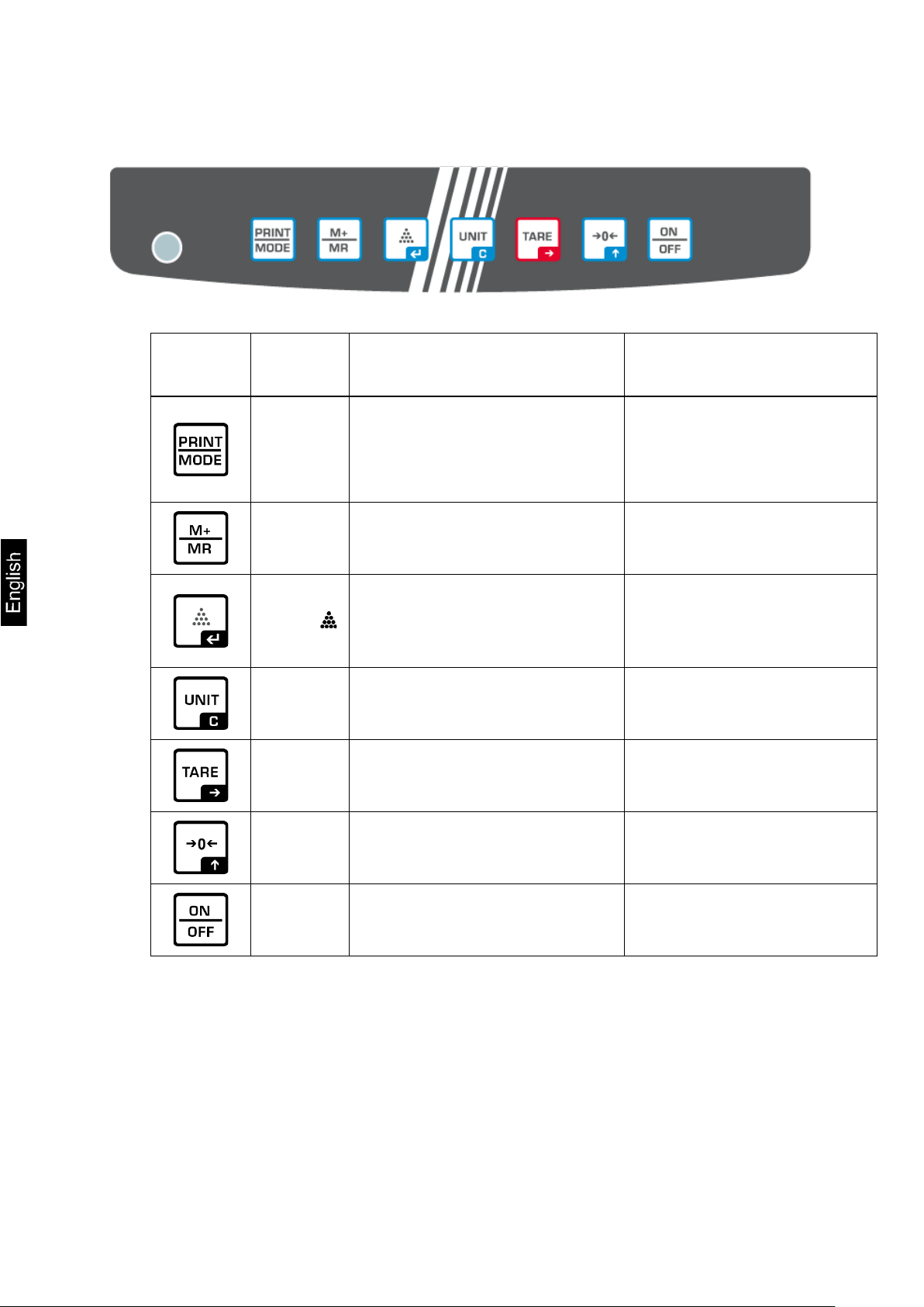
3.2 Keyboard
Button Name Function in the operating
mode
PRINT
button
M Button
Button
UNIT
button
TARE
button
Weight data transfer via the
interface
Summing
Displaying the “total” value
Entering the mean amount
of a single piece
Weigh t unit switching
Deleting the total memory
Taring Navigation button
Menu function
Displaying the
configuration menu
(by pressing and holding
the button)
Selection confirmation
Leaving menu / return to
the weighing mode
ZERO
button
ON/OFF
button
8 TFCD_A-BA-e-2110
Zeroing Navigation button
Switching on/off

∑
oz
LO
OK
HI
3.2.1 Introducing the numerical value
Button Name Function
Navigation button Selection of the right-hand digit
Navigation button Increasing the digit value (0–9)
3.3 Display
Symbol Description
ZERO Zero indicator
GROSS Gross weight value indicator
Navigation button
Battery charging indicator
Discharged battery
Tolerance symbols for check weighing
Stabilization indicator
Confirmation of the enter ed data
NET Net weight value indicator
TARE Weighing data is included in the tare memory
g
kg
lb
Weighing data is included in the total memory
Weight unit “gram”
Weight unit “kilogram”
Weight unit “pound”
Weight unit “ounce”
Negative value indicator
TFCD_A-BA-e-2110 9

4 Basic instructions (general information)
4.1 Intended use
The scale you bought is intended for weighing the weighed material. It should be
considered a “non-automatic scale”, e.g. the weighed material should be carefully
placed manually on the scale plate center. The weight can be read after it has
stabilized.
4.2 Non-intended use
The scale is not intended for dynamic weighing, e.g. for removing or adding small
amounts of the weighed material. The scale’s “stabilizing and compensating”
mechanism can result in displaying erroneous weighing results! (Example: slow
outflow of the liquid from the container placed on the scale.)
Do not subject the plate to long-term load. This may damage the weighing
mechanism.
Avoid any scale im pact and over load higher than t he stipulat ed maximu m load (Max),
deducting the tare from the existing load. This could damage the scale.
Never operate the scale in explosive atmospheres. The standard version is not
explosion-proof.
Never introduce any structural modifications t o the scale. T his may resul t in displayin g
erroneous weighi ng results, v iolating th e technical s afety condi tions, and also in scale
damage.
The scale should always be operated in line with the provided guidelines. Other
operation ranges / areas require a written consent of KERN.
4.3 Guarantee
The warranty expires:
• if you fail to follow our guidelines included in the user manual;
• if you fail to use the device in line with the intended use;
• if you introduce any modifications or open the device;
• if the device gets damaged mechanically or damaged by the utilities, liquids and
ordinary wear and tear;
• if the device is not set correctly or the electrical system is not as required;
• if the weighing mechanism gets overloaded.
10 TFCD_A-BA-e-2110

Before you set and start the device, read this user manual thoroughly
Please keep all the parts of the original packaging in case you had to
Protect all the parts, e.g. wind breaker, scale plate, power supply etc.
4.4 Testing equipment supervision
Within the quality assurance system, you must check the technical measurement
properties of the scale and possibly of the available reference weight regularly. To
that aim, the respons ible user should defi ne a r el evant cy cl e, as wel l as the type and
scope of such an inspection. The information on the supervision of the testing
equipment, i.e. sc ales, and the required refer ence weig hts, can be found on the home
page of KERN (www.kern-sohn.com). The reference weights and scales can be
calibrated fast and for a low cost in the KERN calibration laboratory (against the
national reference) ap pr ov ed by DKD (Deutsche Kalibrierdienst).
5 Basic safety instructions
5.1 Compliance with the instructions included in the user manual
even if you are familiar with KERN scales.
All language versions contain non-binding translation.
Only the original document in German is binding.
5.2 Personnel training
The device can be operated and maintained solely by trained workers.
6 Transport and storage
6.1 Checking during reception
Immediately after you have received the shipment, please check if it is free from any
visible outer damage. The same applies for the unpacked device.
6.2 Packaging / return transport
send it back to us.
Always use the original packaging for the return transport.
Before you dispatch the device, disconnect any connected cables as
well as loose/moving parts.
Reinstall any transport locks, if present.
from slipping and damage.
TFCD_A-BA-e-2110 11

7 Unpacking, positioning and s tart-up
7.1 Installation place, operation place
The scales are designed to ensure reliable weighing results in standard operating
conditions.
The choice of a correct scale location ensures its accurate and fas t o per ati o n.
This is why you should follow the following rules when selecting the
installation place:
• Place the scale on stable, flat surface.
• Avoid extreme temperatures and temperature fluctuations, occurring e.g.
when you place it at the radiator or in a place exposed to direct sun rays.
• Protect the scale from the dir ect draft present at open windows and doors.
• Avoid impact when weighing.
• Protect the scale from high hu midi ty of air, vapors and dust.
• Do not expose it to long-term heavy moisture. Any forbidden condensation of
the air moisture on the device may occur when a cold device is placed in a
much hotter environment. In such circumstances, leave the device not
connected to the mains for 2 hours to adapt to the ambient temperature.
• Avoid static discharge from the weighed material and scale container.
If there are any electromagnetic fields, static discharge and unstable power supply,
high readout deviations (erroneous weighing results) may occur. In such
circumstances, change the location.
7.2 Unpacking and check
Remove the device and accessories from the packaging, remove the packaging
material and plac e the devic e in the tar get l ocat ion. Check i f al l co mpon ents inc l uded
in the delivery are present and not damaged.
Scope of delivery / standard accessories:
• Scale, see chapter 3.1
• Power supply
• User manual
• Dust cover
12 TFCD_A-BA-e-2110

Always use the origi nal power supply by K ERN. U sing any oth er produc ts
7.3 Integration, setting and leveling
Remove any transport protection at the scale bottom.
Install the scale plates as shown in the drawing.
Place the scale on smooth surface.
Level the scale using the leveling feet. The air bubble in the leveler must be
present in the marked area.
Check leveling at regular intervals.
7.4 Power supply
Check if the scale voltage is set correctly. The scale can be connected to
the mains only when the voltage specified on the scale (sticker) and the
local voltage are identical.
requires KERN consent.
Important information:
Before you start the de vi ce, check the power cord for damage.
The power cord must not have any contact with liquids.
The plug must be always readily available.
TFCD_A-BA-e-2110 13

Always replace the battery with the one of the same type or
s. Exposing the battery to specific environmental
conditions may result in its fire or explosion. It may result in
h liquids,
Do not expose the battery to high pressure or microwave
battery and do
The electrolyt e may be released by the d amaged bat tery. Any
contact of the electrolyte with the skin or eyes may irritate
When you place or replace batteries, always pay attention to
(see the information in the battery
When the power supply is connected, the battery operation
mode is switched off. Al ways r emove t he batte ry f or wei ghin g
in the power supply mode longer than 48 h! (Overheating
r emitted by the battery, its heating,
discoloration or deformation, disconnect it immediately from
7.5 Rechargeable battery operation
PLEASE
NOTE!
The rechargeable battery and the charger are compatible.
Always use the power supply delivered with the scale.
Do not use the scale when charging.
of the type recommended by the manufacturer.
The battery is not protected against all the environmental
impact
serious injuries or material losses.
Protect the battery from fire and heat.
Do not allow the battery to have any contact wit
chemicals or salts.
radiation.
Do not modify any batteries, char ger and do not tamp er them.
Do not use any faulty, damaged or deformed battery.
Do not connect the electrical contacts of the
not use any metal items to short circuit them.
them.
the correct polarity
compartment).
danger).
If you detect any odo
the power supply and, whenever possible, from the scale.
14 TFCD_A-BA-e-2110

7.5.1 Battery charging The rechargeable battery is charged using the supplied power cord.
Before first use, charge the battery for at least 5 hours using the power cord.
The battery sy mbol < > displayed on the s cree n mea ns t hat t he ba tter y c apaci ty
will soon run down. The device may operate ca. 1 hour longer and then it will be
switched off automatically. When the scale operates further without charging, a
blinking <LO-BAT> symbol will be displayed.
Charge the battery using the provided power supply.
When charging, LED informs of the battery status.
red: The battery is being charged
green: The battery is fully charged
7.6 Connecting peripherals
Before you connect or disconnect any extra devices (printer, computer) to/from the
data interface, the scale should always be disconnected from the mains.
Use solely accessories and peripherals supplied by KERN with the scale, being
perfectly compatible with it.
7.7 First start
To get accurate w eighing results using electroni c s cales, ensure the scales achiev es
the appropriate operating temperature (see “Heating time”, chapter 1). During the
heating time, the scale must be connected to the power source (the socket,
rechargeable battery or batteries).
The scale accuracy depends on the local standard gravity.
Always follow the guidelines in the “Adjustment” chapter.
TFCD_A-BA-e-2110 15

tions. The heating time is required for the
• Ensure there are no obj ect s on the scal e pl at e .
7.8 Adjustment
As the stand ard gravity value is not the same in every spot on Earth, every display
with the scale plate connected should be adjusted, in line with the weighing rules
resulting from the laws of physics, to the standard gravity in the scale location
(provided the scale system has not already been subject to factory adjustment in its
location). Such an adjustment process should be carried out during the first start,
following every location change and also in the case of any ambient temperature
fluctuations. To ensure achieving accurate measurement date, it is also
recommended to carry out regular display adjustment also in the weighing mode.
• Prepare the required adjustment weight, see chapter 1.
Whenever possible, adjust using the adjustment weight with the weight
similar to the maximum load of the scale (the adjustment weight is
recommended, see chapter 1). The adjustment may also be carried out using
weights with other nominal values or tolerance classes, but this is not optimal
from the measurement technique perspective. The adjustment weight
precision must correspond to the interval [d] of the scale, though preferably it
should be a bit higher. For information concerning reference weights, see
online at: http://www.kern-sohn.com
• Ensure stable environmental condi
stabilization (see chapter 1).
What to do:
Switch the scale on and when the autotest is carried out, press and hold the
button until the < > is displayed.
Release the button . < > and then the blinking symbol of the first
adjustment point will be displayed.
Using the ZERO button, select the required adjustment weight, see chapter 1
“Adjustment points” or “Recommended adjustment weight”.
Place the adjustment weight and confirm by pressing .
Wait until < > is displayed.
Remove the adjustment weight.
Press . After the successful adjustment, the scale will switch to the weighing
mode again automatically.
If there is any adjustment error or if an incorrect adjustment weight is used, the
error message is displayed. Repeat the adjustment process.
16 TFCD_A-BA-e-2110

8 Operation
8.1 Switching on/off Switching on:
Press the ON/OFF button.
Once the displays is lit, the scale autotest will be carried out.
Wait until the weight is displayed, the scale is ready for use.
Switching off:
Press the ON/OFF button, the display will go off.
8.2 Zeroing
Zeroing corrects the effect of small pollutants on the scale plate.
Remove the load from the scale.
Press ZERO, the zero indications and <ZERO> symbol will be displayed.
8.3 Ordinary weighing
Check the zero indication, whenever required zero by pressing the ZERO
button.
Place the weighed material.
Wait until the stabilization indicator is displayed [ ].
Read out the weighing result.
Overload warning
Always avoid any device overload higher than the stipulated maximum
load (Max), deducting the tare from the existing load. This could damage
the device.
The exceeded maximum load is indicated with --ol--. Reduce the scale
load or reduce the initial load.
TFCD_A-BA-e-2110 17

After the load is removed from the scale, the tare weight is displayed as a
To delete the saved tare value, remove the load from the scale plate and
The taring process can be repeated any number of times, e.g. when
weighing several mixture ingredients (making up the weight). The limit is
8.4 Weighing with tare
The empty weight of any container used for weighing can be tared, pressing the
button which results in displaying the net weight of the weighed material during
consecutive weighing pr oc ess es.
Place the scale container on the scale plate.
Wait until the stabilization indicator is displayed [ ], and press the TARE
button. The container weight is saved in the scale memory. Zero, “TARE” and
“NET” are displayed.
“NET” indicates all displayed weight values are net values.
Place the weighed material.
Wait until the stabilization indicator is displayed [ ].
Read out the net weight.
•
negative value.
•
press TARE button.
•
reached when the complete taring scope is used.
18 TFCD_A-BA-e-2110

kg
on/off
hj
on/off
tj
on/off
pr [%]
on/off
8.5 Weight unit switching
When you press UNIT in the wei ghing mode, you may swi tch betwee n the indicatio ns
and the enabled weight units or application units.
Activating the switchable weight units:
Press UNIT and hold it for 3 s until < > is displayed.
Using the TARE button, select the required setting.
You can choose:
lb on/off
oz on/off
cj on/off
pc [pcs] on/off
Using the ZERO button, enable (on) or disable (off) the selected unit.
Using TARE, select the next unit and enable/disable it by pressing ZERO.
The process should be repeated for every unit.
Confirm by pressing , the scale will switch to the weighing mode again.
Weight unit switching
In the weighing mode the UNIT button enables to switch between the enabled
weight units.
The switching function is available solely in the weighing mode.
TFCD_A-BA-e-2110 19

8.6 Percentage weighing
Percentage weighing enables to display the percentage weight in reference to the
reference weight.
Ensure the application unit [%] is enabled, see chapter 8.5.
Using the UNIT button, select the application unit [%].
< > will be displayed.
Place the reference weight corresponding to 100%.
Wait until the stabilizati on in dicat or i s dis play ed a nd the n c onfir m by pressi ng
.
< > will be displayed.
Confirm by pressing , < > symbol will be displayed.
Remove the reference weight, < > will be displayed.
From now on, the sample weight is displayed as percentage referring to the
reference weight.
20 TFCD_A-BA-e-2110

For small or highly diverse pieces, the reference value must be sufficiently
pieces, see the “Technical
8.7 Counting the number of pieces
Before it is possible to count pieces using the scale, you should determine the
average weight of an individual piece (unit weight), the so-called reference value. To
do it, place the specific number of pieces which the counting the number of pieces
will be carried out for. The scale will determine the total weight which will be divided
by the number of pieces, the so-called reference piece number. Next, based on the
calculated mean weight of an individual piece, the number of pieces will be counted.
• The higher number of the reference pieces, the higher the accuracy of
counting the number of pieces.
•
high.
• For the minimum weight of the counted
specification” table.
1. Cal l ing the piece counting mode
Ensure the application unit [pcs] is enabled, see chapter 8.5.
Using the UNIT button, select the application unit [pcs].
< > will be displayed.
2. Setting the reference value
Whenever required, place an empty container on the scale and tare it.
Place the required number of reference items.
Press , the currently set number of referenc e pieces w ill be dis played (e.g. 10)
< >.
Using the ZERO button, select the n umber of reference pieces ( 10, 20, 50, 100,
200, 500) corresponding to the placed reference load and confirm by pressing
.
The mean weight of an individual piece w ill be det ermined by the scale an d then
the piece quantity < > will be displayed.
Remove the reference load. The scale is in the counting mode and counts all
pieces present on the scale plate.
3. Leaving the piece counting mode
Every pressing of the UNIT button results in switching to another weight unit
(e.g. kg).
TFCD_A-BA-e-2110 21

ighed portion is in the pr esent limit r ange, a sou nd
If the weighed portion is below the lower limit value, the
the upper limit value, the
the weighed por tion is in t he present li mit range, a sound
s above the upper limit value, the
8.8 Test weighing
The function is available starting from weight values above 20 d.
Activating the test weighing mode:
In the weighing mode, press TARE, < > will be displayed.
Pressing TARE enables to switch between < > a < >.
< > function deactivated
< > function activated
8.8.1 Test weighing
The <Test weighing> application enables to determine the upper and lower limit
value and, cons equent ly , to e nsure th e w eight of th e w eigh ed m ateri al b elongs t o the
range between the determined tolerance limits.
Exceeding the limit values (fall below and rise above) is signaled with a visual
indication (tolerance symbols , , ) and an audible indication.
Setting conditions of sending and limits:
1. In the weighing mode, press and hold the ZERO, <inside> will be
displayed.
2. Using the ZERO button, select the required signaling condition.
You can choose:
inside
outside
1. If the we
is heard and a tolerance symbol OK is di spl ayed.
2.
sound is not heard and the tolerance symbol UNDER is
displayed.
3. If the weighed portion is above
sound is not heard and the tolerance symbol OVER is
displayed.
1. If
is not heard and a tolerance symbol OK is displayed.
2. If the weighed portion is below the lower l imit value, the
sound is heard and the tolerance symbol UNDER is
displayed.
3. If the weighed portion i
sound is heard and the tolerance symbol OVER is
displayed.
22 TFCD_A-BA-e-2110

, the
If the weighed portion is below the upper limit value, the
If the weighed portion is below the lower limit value, the
If the weighed portion is above the lower limit value, the
Weighed material
Weighed material
Weighed material
and hold it long
hi
1. If the weighed portion is above the upper limit value
sound is heard and the tolerance symbol OVER is
displayed.
2.
sound is not heard and the tolerance symbol UNDER is
displayed.
low
1.
sound is heard and the tolerance symbol UNDER is
displayed.
2.
sound is not heard and the tolerance symbol OVER is
displayed.
3. Confirm the selection by pressing , < > will be d isplayed for a while.
The window for value entry in the numerical form will be displayed where you
can enter the lower limit value. The tolerance symbol will be displayed, the
active item is blinking.
4. Enter the lower limit value (for entering the numerical value see chapter 3.2.1)
and confirm.
5. < > will be displayed for a while. The window for value entry in the
numerical form wi l l be di spl ayed where you can enter the up per li mit value. The
tolerance symbol will be displayed, the active item is blinking.
6. Enter the upper limit value (for entering the numerical value see chapter 3.2.1)
and confirm.
7. < > will be displayed for a while, the scale will switch to the weighing mode
again.
Tolerance check start:
Ensure the test weighing mode is active. To do it, press TARE and hold it long
enough for < > to be displayed.
Place the weighed mat erial (< 20 d) and , based on the t olerance symbol s / audible
signal, check if the weighed material belongs to the pr eset tolerance range.
below
the preset tolerance
in the preset
tolerance range
above
the preset tolerance
• To cancel the limit values, enter <00000.0 kg>.
• Deactivate the test weighing mode. To do it, press TARE
enough for < > to be displayed.
TFCD_A-BA-e-2110 23

enough for < > to be displayed.
8.8.2 Check counting
The <Test counting> application enables to determine the upper and lower limit
value and, consequently, to ensure that the target number of pieces belongs to the
range between the determined tolerance limits.
When the target value i s ac hi eved, the sound is heard an d an opti c al signal is visibl e
(tolerance symbols , , ).
Setting conditions of sending and limits:
Using the UNIT button, select the application unit [pcs].
< > will be displayed.
Press ZERO and hold it for 3 s, <inside> will be displayed.
Using the ZERO button, select the required signaling condition. For selection
options see chapter 8.8.1 / step 2:
Confirm the selection by pressing , < > will be displayed for a while.
The window for value entry in the numerical form will be displayed where you
can enter the lower limit value. The tolerance symbol will be displayed, the
active item is blinking.
Enter the lower limit value (for entering the numerical value see chapter 3.2.1)
and confirm.
< > will be displayed for a while. The window for value entry in the
numerical form wi l l be di spl ayed where you can enter the up per li mit value. The
tolerance symbol will be displayed, t he active item is blinking.
Enter the upper limit value (for entering the numerical value see chapter 3.2.1)
and confirm.
< > will be displayed for a while, the scale will switch to the weighing mode
again.
Tolerance check start:
Ensure the average weight of a single piece is determined (see chapter 8.7.)
Place the weighed material (< 20 d) a nd, based on th e tolerance symbols / audible
signal, check if the weighed material belongs to the preset tolerance range.
Weighed material
below
the preset tolerance
Weighed material
in the preset tolerance
Weighed material above
the preset tolerance
• To cancel the limit values, enter <00000>.
• Deactivate the test weighing mode. To do it, press TARE and hold it long
24 TFCD_A-BA-e-2110

8.9 Summing
The function enables to add individual weighing values to the total memory by
pressing the button.
The function is available starting from weight values above 20 d.
Summing the weighed material:
Whenever required, place an empty container on the scale and tare it.
Place the first weighed material. Wait until the stabilization indicator [ ] is
displayed and then press M. The weight value will be saved. The ∑ symbol will
be displayed.
Remove the weighed material. The subsequent weighed material can be added
only when the indication ≤ zero.
Place the second weighed material. Wait until the stabilization indicator [ ] is
displayed and then press M. The weight value will be added to the total memory.
The total will be displayed alternately with the currently placed weight for ca. 5 s.
Whenever required, add the subsequent weighed material as described above.
Load should be removed from the scale between consecutive weighing
procedures.
This process may be repe ated 99 ti mes until you reach t he scal e weighi ng range.
Displaying the “total” value:
When zero is displayed, press M. The total weight will be displayed for ca. 5 s.
Deleting the total memory:
When zero is displayed, press the M button. When the total weight is displayed,
press UNIT.
TFCD_A-BA-e-2110 25

for 3 s.
consecutively, pressing TARE.
be displayed.
available settings.
9 Setup menu
The setup menu enables to adapt the scale settings / scale behavior to your
requirements (e.g. ambient conditions, special weighing processes).
Menu navigation:
Displaying the menu In the weighing mode, press and hold the PRINT
Selecting the menu item Individual menu items can be selected
Setting selection Confirm the selection of the menu item by
pressing the ZERO button. The current setting will
Changing settings The TARE button enables to switch between the
Setting confirmation /
Menu leaving
Overview:
Main menu
block
BuAd96
Transmission
speed
RS CO
Data
Submenu
item
BuAd96* Transmission spe ed 9 600
BuAd48 Transmission speed 4 800
rS oFF Data transmission off
rS Co Continuous data trans mi ss i on of st able/unstable
transmission
rS SCo* Continuous data transmission of stable weighing
rS St Data transmission for an unstable weighing value
rS Co Data transmission after PRINT is pressed
bl-AY
bl-AY* The backlight is switched on automatically when load
Display
backlight
bl-on Display backlight always on
Press , the scale will switch to the weighing
mode again.
Available
settings / explanation
weighing values
values
is changed or when the device is operated
bl-oFF Display backlight a lways off
FiLt-1
FiLt-1* ∼
FiLt-5
Filter
26 TFCD_A-BA-e-2110
Adaptation to the ambient conditions,
you can select from FiLt-1 ∼ FiLt-5.
The higher the filter degree, the faster the response
time/but also the higher the sensitivity.

Automatic zero maintenance, possible to choose from
significantly, the scale’s “stabilizing and compensating”
The load scope where the scale returns to zero, you can
Zero-1
Maintaining zero
L-AZ-0
Setting
a decimal point
ZEro0* ∼
ZEro9
L-AZ 0* ∼
L-AZ 9
0 d to 9 d
If the amount of the weighed material is reduced or increased
mechanism can resu lt in displaying erroneo us weighing results!
(e.g.: slow outflow of the liquid fro m the container placed on th e
scale, evaporating processes).
When dosing with small weight fluctuations, it is recommended to
switch this function off.
choose from 0 d to 9 d
Factory settings are indicated by “*”.
10 RS-232 interface
RS-232 ensures two-way data exchange between the scale and external devices.
Data is sent asynchronously in ASCII code.
To ensure communication between the balance and the printer, the following
conditions must be met:
• Connect the scale with the printer interface using the appropriate cable.
Trouble-free oper ation is ensured onl y when t he appropr iate inter face cabl e by
KERN is used.
• Communication parameters (e.g. transmission speed) of the scale and the
printer must be compliant.
10.1 Technical specification
Port 9-Pin--pin mini D-Sub plug
Pin 2 RXD Input
Pin 3 TXD Output
Pin 5 GND Signal ground
Transmission
The choice of 4800/9600
speed
TFCD_A-BA-e-2110 27

10.2 Printer mode / protocol templates (KERN YKB-01N)
Weighing: + 1.0745 kg
+ 0.8735 kg
Counting the number of
+ 200PC
pieces
Percentage weighing + 100.00%
Summing No possibility to connect with the printer
10.3 Printout protocol (continuous data transmission)
Byte 1 2 3 4 5 6 7 8 9 10 11 12 13
+ <20> <20> 1 0 7 4 . 5 g <CR> <LF>
– <20> <20> <20> <20> 5 0 . 6 g <CR> <LF>
O L
Nr Description
1 The sign (plus/minus); alphabet: O
2 ∼ 8
9 ∼ 10
11 ∼ 12
7 bits of weighing value including the decimal point
Weight unit
End symbol
<20> Space
28 TFCD_A-BA-e-2110

t any works related to the maintenance, cleaning and
11 Maint enance, service and disposal
Before you star
repair, disconnect the device from the operating voltage.
11.1 Cleaning
Do not use any aggressive cleaning agents (solvents etc.), but clean the device with
a cloth and mild soap s ol uti on . T he l iqui d must not get inside the device. Wipe with a
dry, soft cloth.
Any loose specimen/powder remains can be removed carefully with a brush or a
handheld vacuum cleaner.
Remove any scattered weighed material immediately.
11.2 Maintenance and service
The device can be ope rated and maintai ned sol ely by th e technici ans trained an d
authorized by KERN.
Disconnect from the mains befor e op eni ng .
11.3 Disposal
The packaging and the devic e shoul d be di spos ed in acc ordanc e wi th the n ation al or
regional law in the location where the device is operated.
12 Error messages
Error message Explanation
--ol-- Overloading
B-ERR Discharged batteries /rechargeable batteries
Err 9 Summing error
P-ERR Average weight of a single piece outside the range
TFCD_A-BA-e-2110 29

13 Help for any minor failures
If there are any program execution problems, the scale should be switched off and
disconnected from the mains for a while. Next, the weighing process should be
started anew.
Problem Possible cause
The weight indicator is not
lit.
The weight indication
keeps fluctuating.
The weighing result
is clearly wrong.
• The scale is not on.
• Interrupted mains connection (mains cable not
connected/damaged).
• Mains voltage failure.
• Draft / air movements.
• Table/air vibrations.
• The scale plate is in contact with foreign bodies.
• Electromagnetic fiel ds / stati c di s char ge (select
another location / if possible, switch off the
interfering device).
• The scale indication was not reset.
• Incorrect adjustment.
• Scale not placed on a level surface.
• There are heavy temperature fluctuations.
• The heating time not observ ed.
• Electromagnetic fields / static discharge (select
another location / if possible, switch off the
interfering device).
30 TFCD_A-BA-e-2110
 Loading...