

Page 1
KERN & Sohn GmbH
Ziegelei 1
E-Mail: info@kern-sohn.com
Phone: +49-[0]7433- 9933-0
Internet: www.kern-sohn.com
Operating and Installati on Instructions
Display devices
KERN KFB/KFN-TM
Version 2.0
02/2012
GB
D-72336 Balingen
Fax: +49-[0]7433-9933-149
KFB/KFN-TM-BA_IA-e-1220
Page 2
KERN KFB/KFN -TM
Display units
GB
Version 2.0 02/2012
Operating and installa t ion instructions
Contents
1 Technical data ................................................................................................ 4
2 Appliance overview ....................................................................................... 5
2.1 Keyboard overview ..................................................................................................................... 7
2.1.1 Numerical input via the navigation buttons................................................................................. 8
2.2 Overview of display .................................................................................................................... 8
3 Basic Information (Gen eral) .......................................................................... 9
3.1 Proper use .................................................................................................................................. 9
3.2 Improper Use .............................................................................................................................. 9
3.3 Warranty ..................................................................................................................................... 9
3.4 Monitoring of Test Resources .................................................................................................. 10
4 Basic Safety Precauti o ns ............................................................................ 10
4.1 Pay attention to the instructions in the Operation Manual........................................................ 10
4.2 Personnel training ..................................................................................................................... 10
5 Transport and storage ................................................................................. 10
5.1 Testing upon acceptance ......................................................................................................... 10
5.2 Packaging / return transport ..................................................................................................... 10
6 Unpacking and placing ................................................................................ 11
6.1 Installation Site, Location of Use .............................................................................................. 11
6.2 Unpacking ................................................................................................................................. 11
6.3 Scope of delivery / serial accessories: ..................................................................................... 11
6.4 Transportation lock (illustration example) ................................................................................. 12
6.5 Error message .......................................................................................................................... 12
6.6 Placing ...................................................................................................................................... 13
6.7 Mains connection ...................................................................................................................... 14
6.8 Storage battery operation (optional) ......................................................................................... 14
6.9 Adjustment ................................................................................................................................ 15
6.9.1 Verified weighing systems ........................................................................................................ 15
6.9.2 Not verifiable weighing systems ............................................................................................... 18
6.10 Linearization ............................................................................................................................. 19
6.10.1 Verified weighing systems:................................................................................................... 19
6.10.2 Non-verified weighing systems ............................................................................................ 20
6.11 Verification 21
2 KFB/KFN-TM-BA_IA-e-1220
Page 3

7 Operation ...................................................................................................... 24
7.1 Start-up ..................................................................................................................................... 24
7.2 Switching Off ............................................................................................................................ 24
7.3 Zeroing ..................................................................................................................................... 24
7.4 Simple weighing ....................................................................................................................... 24
7.5 Switch-over weighing unit (only not verifiable weighing systems) ........................................... 25
7.6 Weighing with tare .................................................................................................................... 26
7.7 Weighing with tolerance range ................................................................................................. 26
7.8 Manual totalizing ....................................................................................................................... 29
7.9 Automatic adding-up ................................................................................................................. 31
7.10 Parts counting ........................................................................................................................... 32
7.11 Animal weighing ....................................................................................................................... 33
7.12 Lock keyboard .......................................................................................................................... 34
7.13 Display background illumination ............................................................................................... 34
7.14 Automatic switch-off function „AUTO OFF“ .............................................................................. 35
8 Menu ............................................................................................................. 36
8.1 Overview non verifiable weighing systems (contacts of circuit board [K1] not short-circuited) 37
8.2 Overview verified weighing systems (contacts of circuit board [K1] short-circuited by means of
jumper) 39
9 Service, maintenance, disposal .................................................................. 43
9.1 Clean ........................................................................................................................................ 43
9.2 Service, maintenance ............................................................................................................... 43
9.3 Disposal .................................................................................................................................... 43
9.4 Error messages ........................................................................................................................ 43
10 Data output RS 232C ................................................................................... 45
10.1 Technical data .......................................................................................................................... 45
10.2 Printer mode ............................................................................................................................. 46
10.3 Output log ................................................................................................................................. 46
10.4 Remote control instructions ...................................................................................................... 46
11 Instant help ................................................................................................... 47
12 Installing display unit / weighing bridge .................................................... 48
12.1 Technical data .......................................................................................................................... 48
12.2 Weighing system design........................................................................................................... 48
12.3 How to connect the platform ..................................................................................................... 49
12.4 Configure display unit ............................................................................................................... 50
12.4.1 Verified weighing systems (contacts of circuit board [K1] short-circuited by means of
jumper) 50
12.4.2 Non verifiable weighing systems (contacts of circuit board [K1] not short-circuited ) .......... 56
13 Declaration of Conformity / Type Approval Certificate / Test Certificate 60
KFB/KFN-TM-BA_IA-e-1220 3
Page 4
1 Technical data
KERN KFB-TM KFN-TM
Display 5 ½ - digit
Resolution (verified) 6000
Single (Max.) 6.000 e
Dual (Max.) 3.000 e
Resolution (non-verified) 30.000
Weighing ranges 2
Divisions 1,2,5,…10n
Weighing Units kg
Functions
Display LCD 52 mm digits with back lighting
DMS weighing cells
Range calibration We recommend ≥ 50 % max.
Data output RS232
Electric Supply
Housing 250 x 160 x 58 266 x 165 x 96
Admissible
ambient temperature
Net weight 1.5 kg 2 kg
Rechargeable battery
(optional)
Operating / charge time
Weighing with tolerance range, Totalizing, Animal
weighing
80-100 Ω. Max. 4 item per 350 Ω;
Sensitivity 2-3 mV/V
Input voltage 220 V – 240 V, 50 Hz
Power pack secondary voltage 9V, 800mA
0°C – 40°C (non-verified)
-10°C – 40°C (verified)
35 h / 12 h 90 h / 12 h
RS 232 interface Standard Option
Tripod KERN BFS-07, option
Support base
incl. wall bracket
IP protection -
4 KFB/KFN-TM-BA_IA-e-1220
Standard
IP 67 as per DIN 60529
(rechargeable battery
operation only)
Page 5
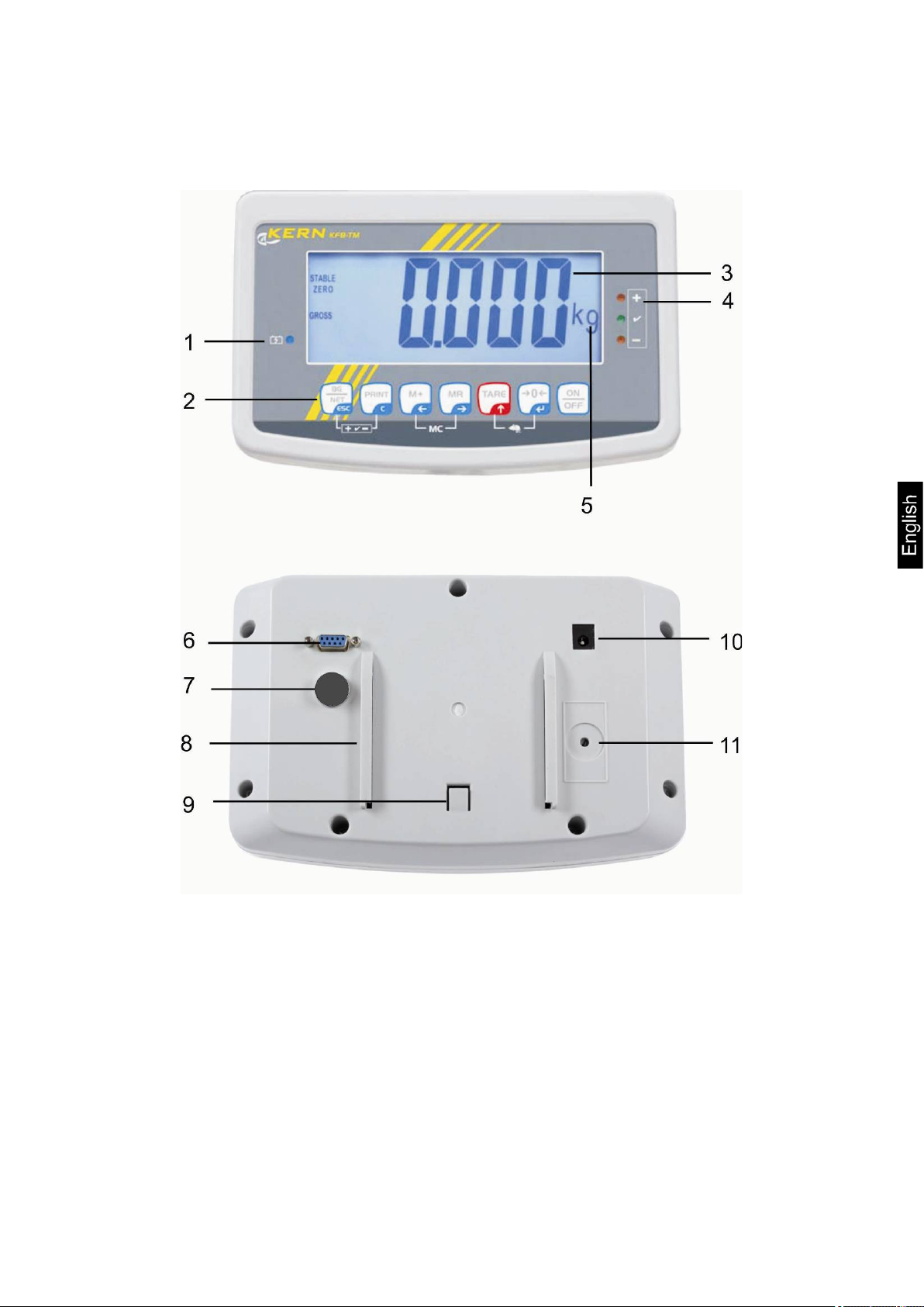
2 Appliance overview
KFB-TM: Synthetic finis h
1. Status of rechargeable battery
2. Keyboard
3. Weight display
4. Tolerance margin, see chap. 7.7
5. Weighing unit
6. RS-232
7. Input connection load cell cable
8. Guide rail support base / stand
9. End stop support base / stand
10. Mains adapter connection
11. Adjustment switch
KFB/KFN-TM-BA_IA-e-1220 5
Page 6
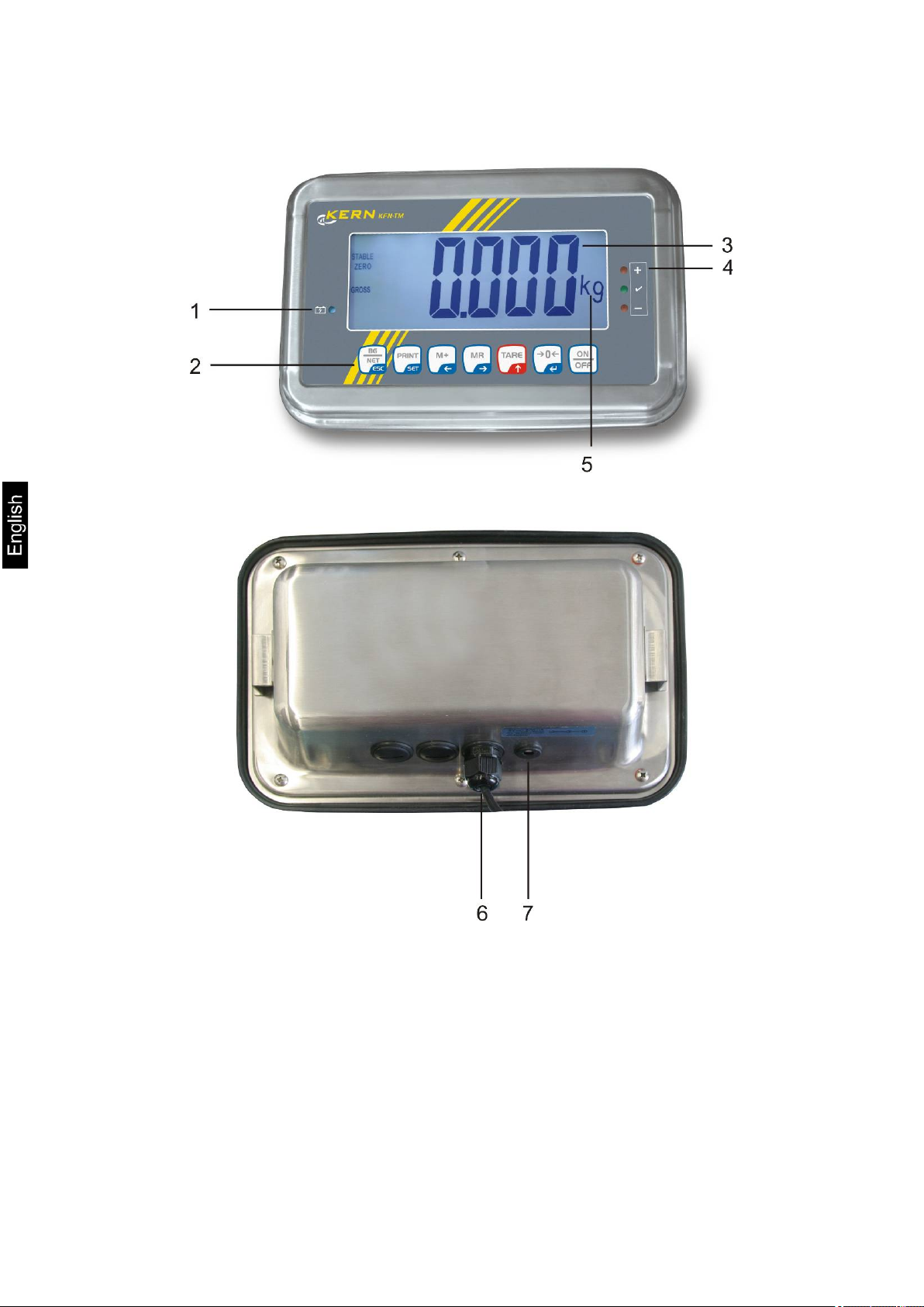
KFN-TM: Stainless steel finish
1. Status of rechargeable battery
2. Keyboard
3. Weight display
4. For tolerance mark see chap. 7.7
5. Weighing unit
6. Input connection load cell cable
7. Mains adapter connection
6 KFB/KFN-TM-BA_IA-e-1220
Page 7
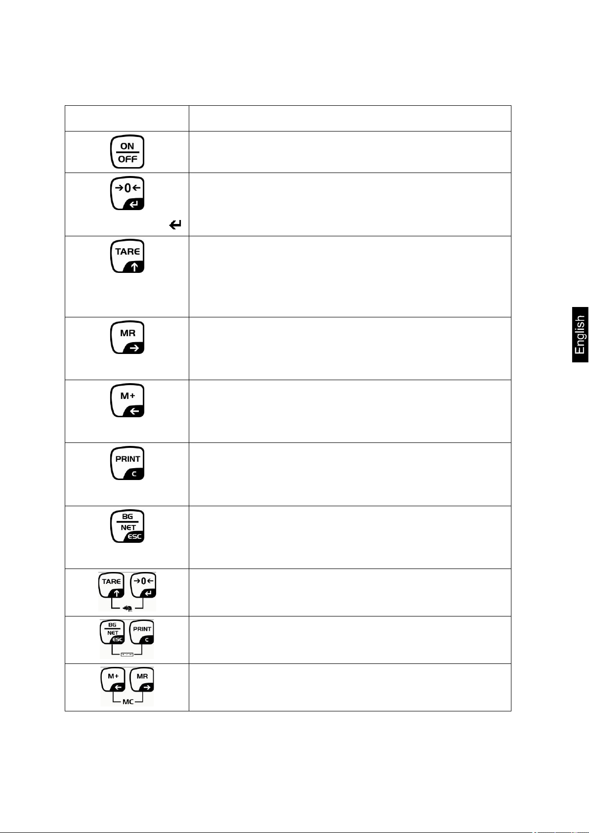
2.1 Keyboard overview
Key Function
• Turn on/off
• Zeroing
Navigation button
Navigation key
Navigation key
Navigation key
C
• Confirm entry
• Taring
• At numeric input increase flashing digit
• Scroll forward in menu
• Display sum total
• Digit selection to the right
• Add weighing value to summation memory
• Digit selection to the left
• Calculate weighing data via interface
• Delete
• Change between gross and net weight
ESC
KFB/KFN-TM-BA_IA-e-1220 7
• Back to menu/weighing mode
• Call up animal weighing function
• Call up weighing with tolerance range
• Delete total added memory
Page 8
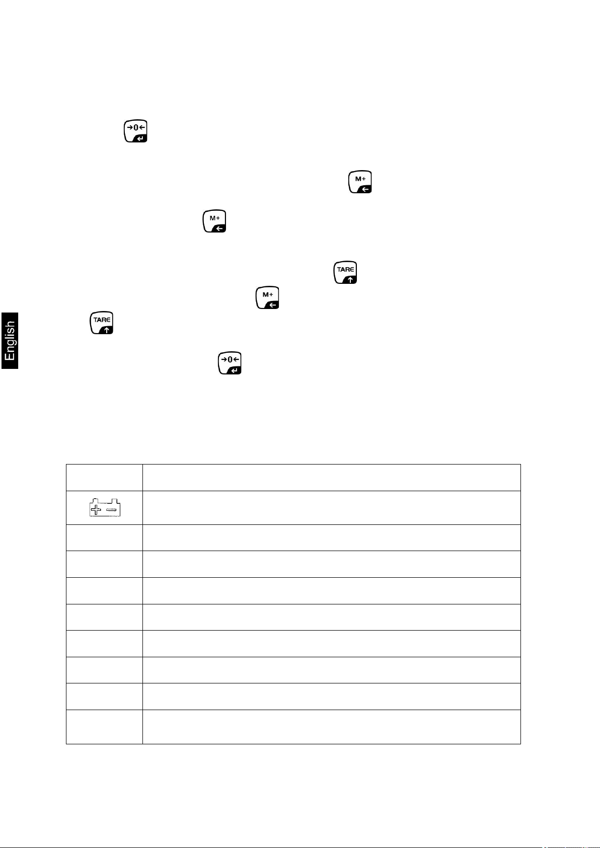
2.1.1 Numerical input via the navigation buttons
Press and current setting will be displayed. The first digit will be flashing
and is ready for changing.
If you do not wish to change the first digit, press and the second digit will
start flashing.
Each time you press , the display will move to the subsequent digit, after the
last digit the display will return to the first digit.
To change the selected (flashing) digit, press repeatedly until the desired
value is displayed. Then press to access further digits and change them by
.
Complete your entry by .
2.2 Overview of display
Display Significance
Battery very low
STABLE Stability display
ZERO Zero indicator
GROSS Gross weight
NET Net weight
AUTO Automatic add-up enabled
Kg Weighing unit
M+ Totalisation
LED
+ / / -
8 KFB/KFN-TM-BA_IA-e-1220
Indicators for weighing with tolerance range
Page 9

3 Basic Information (General)
3.1 Proper use
The display unit acquired by you is used in combination with a weighing plate and
serves to determine the weighing value of material to be weighed. It is intended to be
used as a “non-automatic weighing system”, i.e. the material to be weighed is
manually and carefully placed in the centre of the weighing plate. As soon as a stable
weighing value is reached the weighing value can be read.
3.2 Improper Use
Do not use display unit for dynamic weighings. In the event that small quantities are
removed or added to the material to be weighed, incorrect weighing results can be
displayed due to the “stability compensation“ in the display unit. (Example: Slowly
draining fluids from a container on the balance.)
Do not leave permanent load on the weighing pan. This may damage the measuring
system.
Impacts and overloading exceeding the stated maximum load (max) of the weighing
plate, minus a possibly existing tare load, must be strictly avoided. Both, the weighing
plate and the display unit may be damaged during this process.
Never operate display unit in explosive environment. The serial version is not
explosion protected.
Changes to the display unit's design are not permitted. This may lead to incorrect
weighing results, safety-related faults and destruction of the display unit.
The display unit may only be operated in accordance with the described default
settings. Other areas of use must be released by KERN in writing.
3.3 Warranty
Warranty claims shall be voided in case
• Our conditions in the operation manual are ignored
• The appliance is used outside the described uses
• The appliance is modified or opened
• Mechanical damage or damage by media, liquids, natural wear and tear
• The appliance is improperly set up or incorrectly electrically connected
• The measuring system is overloaded
KFB/KFN-TM-BA_IA-e-1220 9
Page 10
3.4 Monitoring of Test Resources
In the framework of quality assurance the measuring-related properties of the display
unit and, if applicable, the testing weight, must be checked regularly. The responsible
user must define a suitable interval as well as type and scope of this test. Information
is available on KERN’s home page (www.kern-sohn.com with regard to the
monitoring of display units’ test substances and the test weights required for this. In
KERN’s accredited DKD calibration laboratory test weights and display units may be
calibrated (return to the national standard) fast and at moderate cost.
4 Basic Safety Precautions
4.1 Pay attention to the instructions in the Operation Manua l
Carefully read this operation manual before setup and commissioning, even if you
are already familiar with KERN balances.
4.2 Personnel training
The appliance may only be operated and maintained by trained personnel.
5 Transport and storage
5.1 Testing upon acceptance
When receiving the appliance, please check packaging immediately, and the
appliance itself when unpacking for possible visible damage.
5.2 Packaging / return transport
Keep all parts of the original packaging for a possibly
required return.
Only use original packaging for returning.
Prior to dispatch disconnect all cables and remove
loose/mobile parts.
Reattach possibly supplied transport securing devices.
Secure all parts such as the glass wind screen, the
weighing platform, power unit etc. against shifting and
damage.
10 KFB/KFN-TM-BA_IA-e-1220
Page 11

• Display Unit
6 Unpack ing and placing
6.1 Installation Site, Location of Use
The display units are designed in a way that reliable weighing results are achieved in
common conditions of use.
Precise and fast work is achieved by selecting the right place for your display unit
and your weighing plate.
On the installation site observe the following:
• Place the display unit and the weighing plate on a stable, even surface.
• Avoid extreme heat as well as temperature fluctuation caused by installing
next to a radiator or in the direct sunlight;
• Protect the display unit and the weighing plate against direct draft from open
windows or doors.
• Avoid jarring during weighing;
• Protect the display unit and the weighing plate against high humidity, vapours
and dust.
• Do not expose the display unit to extreme dampness for longer periods of
time. Non-permitted condensation (condensation of air humidity on the
appliance) may occur if a cold appliance is taken to a considerably warmer
environment. In this case, acclimatize the disconnected appliance for ca. 2
hours at room temperature.
• Avoid static charge of goods to be weighed or weighing container.
Major display deviations (incorrect weighing results) may be experienced should
electromagnetic fields (e.g. due to mobile phones or radio equipment), static
electricity accumulations or instable power supply occur. Change location or remove
source of interference.
6.2 Unpacking
Take the display unit carefully out of its packaging, remove the plastic jacket and
install it at the designated work space.
6.3 Scope of delivery / serial accessories:
• Mains adapter
• Support base incl. wall bracket
• Operating instructions
KFB/KFN-TM-BA_IA-e-1220 11
Page 12
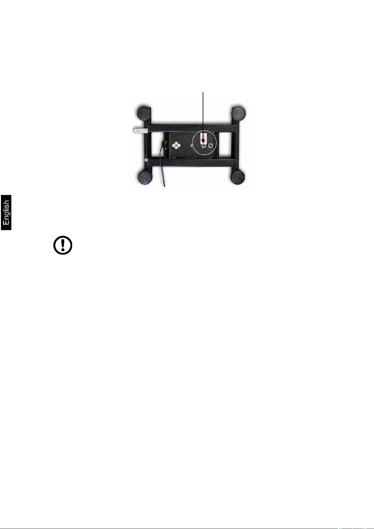
Transport Securing
6.4 Transportation lock (illustration example)
Please note: if the display unit is used together with platform with transportation lock,
this transportation lock must be released prior to use:
6.5 Error message
As soon as an error message appears in the balance display, the
balance must not more be used, e.g. Err 4
12 KFB/KFN-TM-BA_IA-e-1220
Page 13
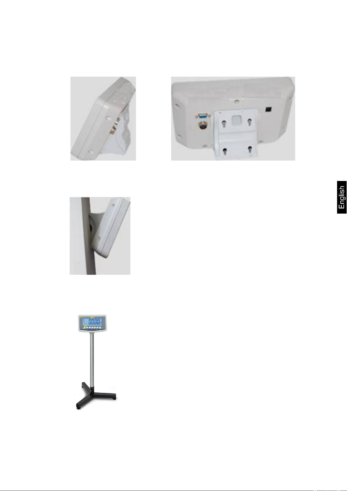
6.6 Placing
Mount the display unit in a way that facilitates operation and where it is easy to see.
Usage with support base (KFB-TM only)
Push support base holder in guide rail [8] up to end stop [9], see chpt 2.
Usage with wall mount (KFB-TM only)
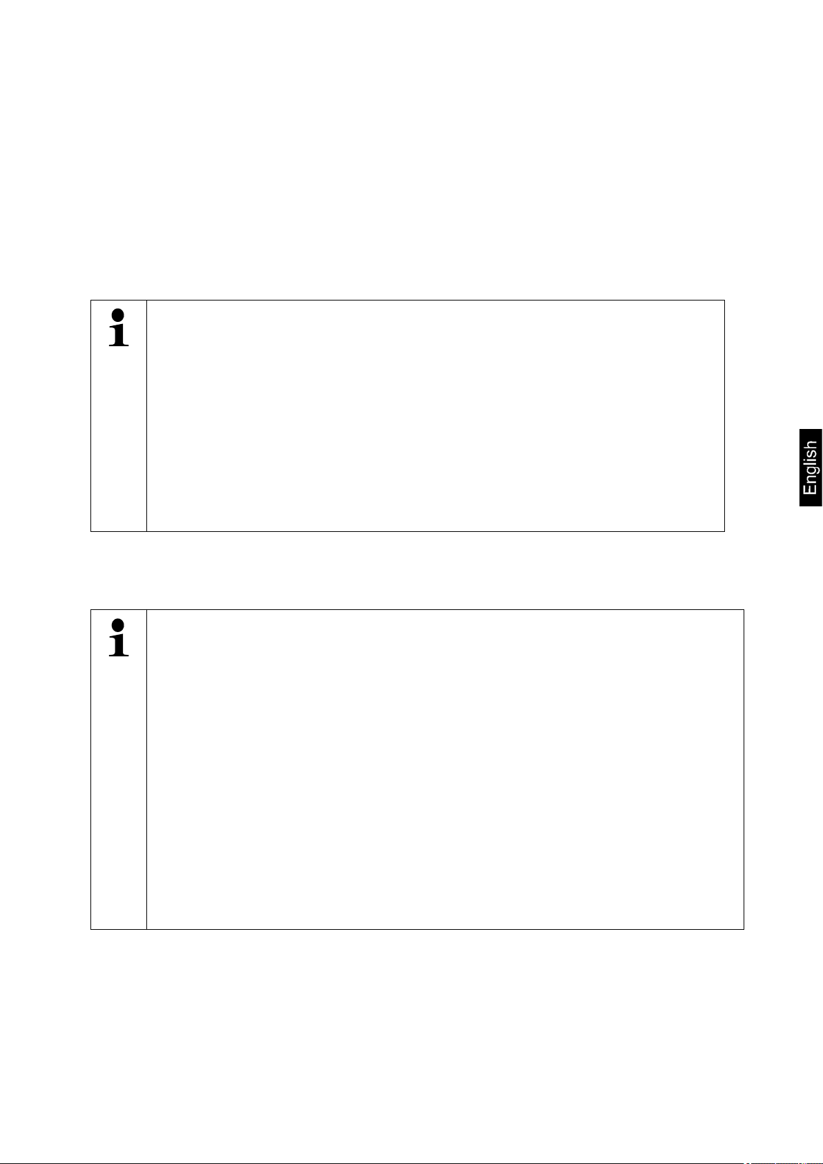
Use the wall mount to affix the display unit to the wall.
Using with tripod (optional)
An optional tripod (KERN BFS-07) is available if the display unit is to be mounted
in a raised position.
KFB/KFN-TM-BA_IA-e-1220 13
Page 14

6.7 Mains connection
Power is supplied via the external mains adapter. The stated voltage value must be
the same as the local voltage.
Only use original KERN mains adapters. Using other makes requires consent by
KERN.
6.8 Storage battery operation (optional)
Before the first use, the battery should be charged by connecting it to the mains
power supply for at least 12 hours.
If the weight display shows , this is an indication that the capacity of the
rechargeable battery is almost exhausted. The unit will be ready for operation for
approx. another 10 hours before switching off automatically. Charge the battery with
the help of the supplied power pack.
The LED display informs you during loading about the loading status of the
rechargeable battery.
red: Voltage has dropped below prescribed minimum.
green: Battery is completely discharged
yellow: Charging storage battery
To conserve energy, enable the automatic switch-off function „AUTO OFF“, see
chap. 7.14.
14 KFB/KFN-TM-BA_IA-e-1220
Page 15
•
6.9 Adjustment
As the acceleration value due to gravity is not the same at every location on earth,
each display unit with connected weighing plate must be coordinated - in compliance
with the underlying physical weighing principle - to the existing acceleration due to
gravity at its place of location (only if the weighing system has not already been
adjusted to the location in the factory). This adjustment process must be carried out
for the first commissioning, after each change of location as well as in case of
fluctuating environment temperature. To receive accurate measuring values it is also
recommended to adjust the display unit periodically in weighing operation.
• In weighing systems with a resolution of < 15 000 dividing steps an
adjustment is recommended.
In weighing systems with a resolution of > 15 000 dividing steps a
linearisation is recommended (see chap. 6.10).
• Prepare the required adjustment weight. The weight to be used depends
on the capacity of the scale. Carry out adjustment as near as possible to
the scale’s maximum weight. Info about test weights can be found on
the Internet at: http://www.kern-sohn.com.
• Observe stable environmental conditions. Stabilisation requires a certain
warm-up time.
6.9.1 Verified weighing systems
In verified weighing systems the menu item for adjustment „P2 mode“ is
blocked.
KERN KFB-TM
To disable the access lock, destroy the seal and actuate the adjustment
switch. Position of the adjustment switch see chap. 6.11
KERN KFN-TM
To override the blocked access you will have to destroy the seal before calling
up the menu and to short-circuit the two contacts on the circuit board [K2],
using a jumper (See chap. 6.11).
Attention:
After destruction of the seal the weighing system must be re-verified by an
authorised agency and a new verification wire/seal mark fitted before it can be
reused for applications subject to verification.
KFB/KFN-TM-BA_IA-e-1220 15
Page 16
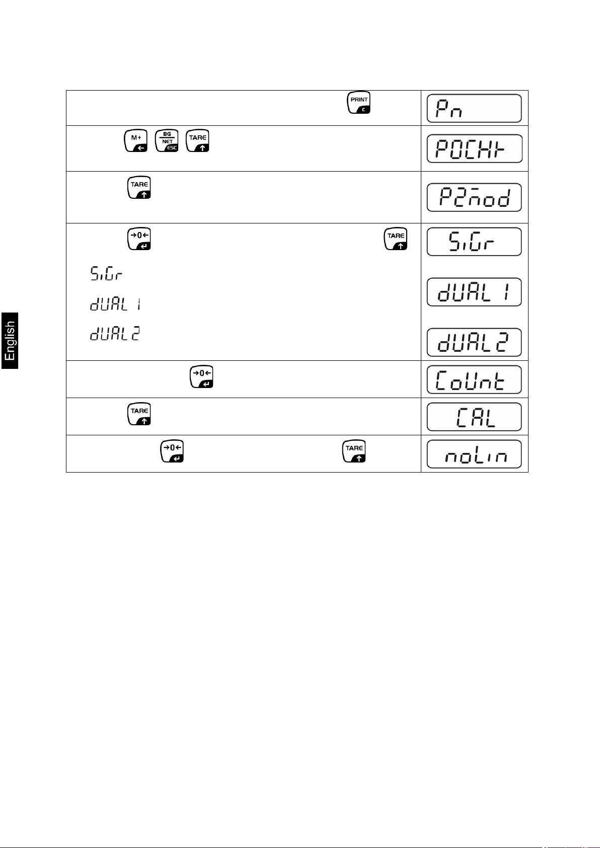
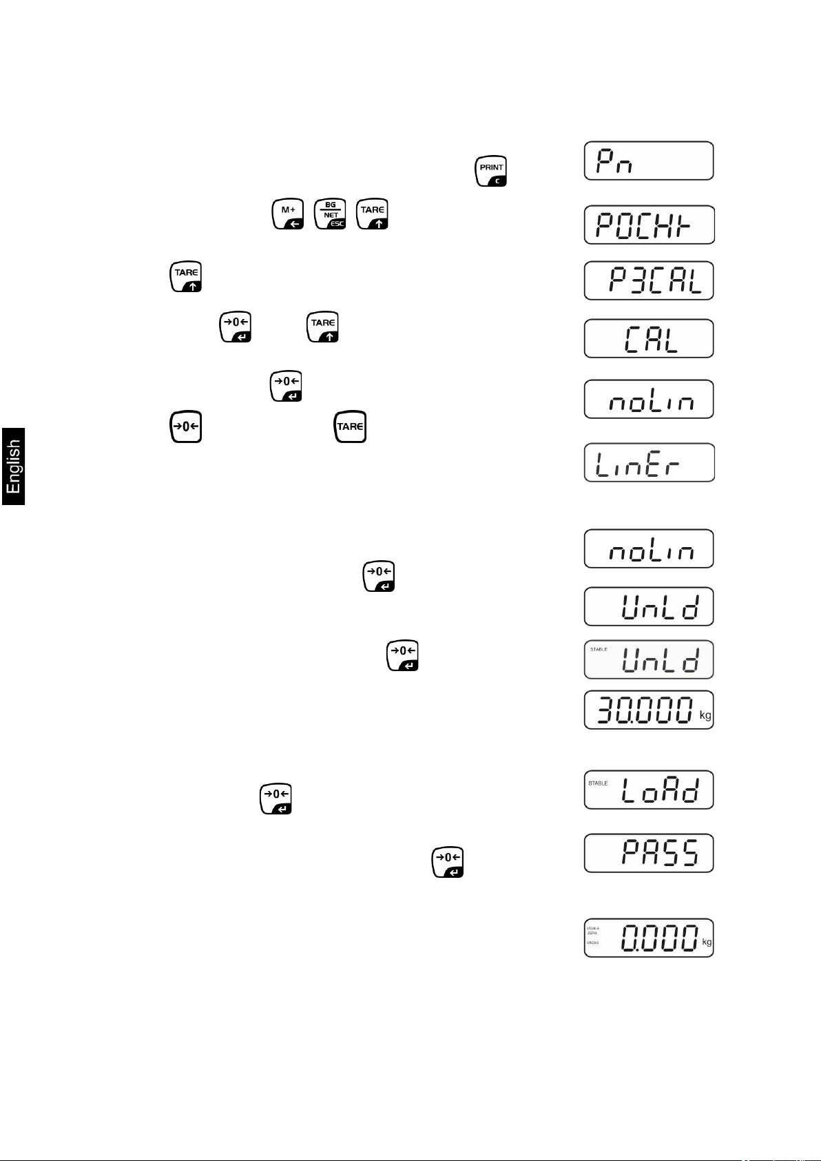
Call up menu:
1. Switch-on balance and during the selftest press .
2. Press , , subsequently, the first menu block
„PO CHK“ will be displayed.
3. Press repeatedly until „P2 mode“ will be displayed.
For the KFB-TM model operate the adjustment switch.
4. Press and select the set weighing scales type by .
= Single-range balance
= Dual range balance
= Multi-interval balance
5. Acknowledge with .
6. Press repeatedly until „CAL“ will be displayed.
7. Confirm with and select setting „noLin“ by .
16 KFB/KFN-TM-BA_IA-e-1220
Page 17
How to carry out an adjustment:
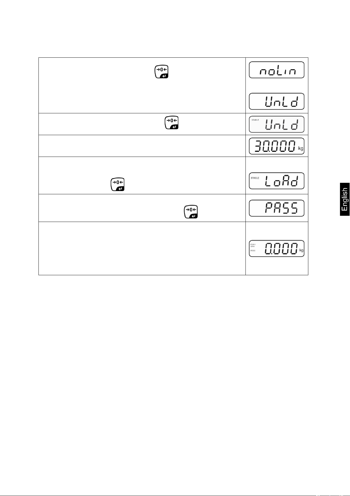
Confirm menu setting „noLin“ by .
Ensure that there are no objects on the weighing plate.
Wait for stability display, then press .
The currently set adjustment weight will be displayed.
To change by using the navigation buttons (see chap. 2.1.1)
select the desired setting, the active digit is flashing.
Acknowledge with .
Carefully place adjusting weight in the centre of the weighing
plate. Wait for stability display, then press .
After the adjustment the balance will carry out a self-test.
Remove adjusting weight during selftest, balance will return
into weighing mode automatically.
An adjusting error or incorrect adjusting weight will be
indicated by the error message; repeat adjustment
procedure.
KFB/KFN-TM-BA_IA-e-1220 17
Page 18
Call up menu:
6.9.2 Non verifiable weighing systems
1. Switch-on balance and during the selftest press .
2. Press subsequently , , the first menu block
„PO CHK“ will be displayed.
3. Press repeatedly until „P3 CAL“ will be displayed.
4. Confirm with ; press repeatedly until „CAL“
appears.
5. Acknowledge using , the current setting is displayed.
Press to confirm; press to select setting.
noLin = adjustment
LineAr = linearization, see chap. 6.10
How to carry out adjustment:
Confirm menu setting „noLin“ by .
Ensure that there are no objects on the weighing plate.
Wait for stability display, then press .
The currently set adjustment weight will be displayed.
To change by using the navigation buttons (see chap. 2.1.1)
select the desired setting, the active digit is flashing.
Acknowledge with .
Carefully place adjusting weight in the centre of the weighing
plate. Wait for stability display, then press .
After the adjustment the balance will carry out a self-test.
Remove adjusting weight during selftest, balance will return
into weighing mode automatically. An adjusting error or
incorrect adjusting weight will be indicated by the error
message; repeat adjustment procedure.
18 KFB/KFN-TM-BA_IA-e-1220
Page 19
• In balances with a resolution of > 15 000 dividing steps carrying out a
the adjustment switch see chap. 6.11
6.10 Linearization
Linearity shows the greatest deviation of a weight display on the scale to the value of
the respective test weight according to plus and minus over the entire weighing
range. If linearity deviation is discovered during a testing instrument control, you can
improve this by means of linearization.
6.10.1 Verified weighing systems:
linearisation is recommended.
• Carrying out linearization is restricted to specialist staff possessing
well acquainted with the workings of weighing scales.
• The test weights to be used must be adapted to the weighing scale’s
specifications; see chapter “testing instruments control”.
• Observe stable environmental conditions. Stabilisation requires a
certain warm-up time.
• After successful linearisation you will have to carry out calibration;
see chapter “testing instruments control”.
• The adjustment is locked for verified balances. To disable the access
lock, destroy the seal and actuate the adjustment switch. Position of
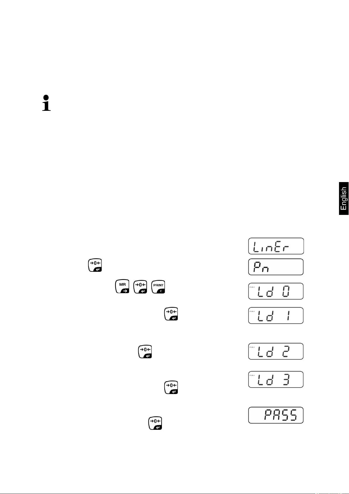
Menu item P2 modeCalCall up liner, see chap. 6.9.1
Confirm by , the password query „Pn“ will be displayed.
Press subsequently , , .
Ensure that there are no objects on the weighing pan.
Wait for stability display, then press .
When “Ld 1“ is displayed, put the first adjustment weight (1/3
max) carefully in the centre of the weighing platform. Wait for
stability display, then press .
When “Ld 2“ is displayed, put the second adjustment weight
(2/3 max) carefully in the centre of the weighing platform.
Wait for stability display, then press .
When “Ld 3“ is displayed, put the third adjustment weight
(max) carefully in the centre of the weighing platform. Wait
for stability display, then press .
KFB/KFN-TM-BA_IA-e-1220 19
Page 20
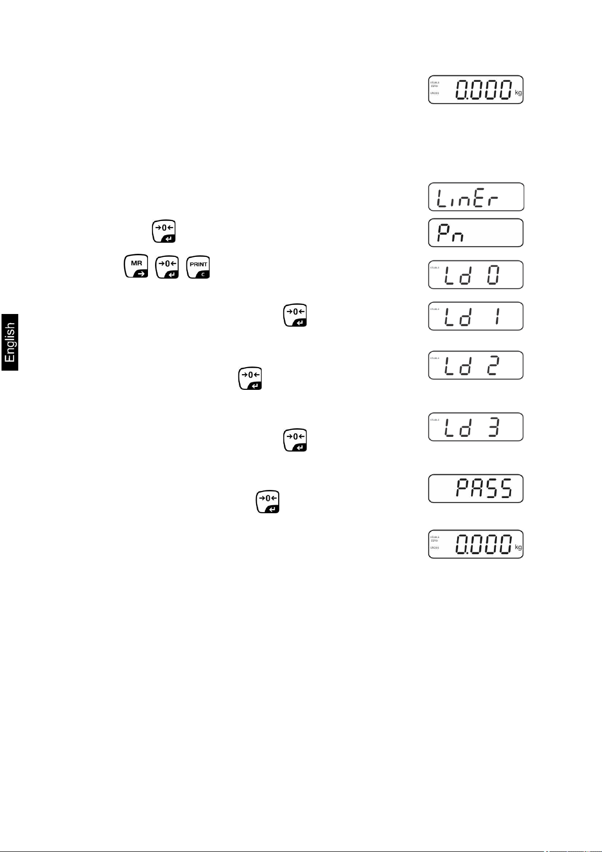
After linearisation the balance will carry out a self-test.
Remove adjusting weight during selftest, balance will return
into weighing mode automatically.
6.10.2 Non-verified weighing systems
Call-up menu item P3 CALCalLiner, see chap. 6.9.1
Confirm by , the password query „Pn“ will be displayed.
Press , , subsequently.
Ensure that there are no objects on the weighing pan.
Wait for stability display, then press .
When “Ld 1“ is displayed, put the first adjustment weight (1/3
max) carefully in the centre of the weighing platform. Wait for
stability display, then press .
When “Ld 2“ is displayed, put the second adjustment weight
(2/3 max) carefully in the centre of the weighing platform.
Wait for stability display, then press .
When “Ld 3“ is displayed, put the third adjustment weight
(max) carefully in the centre of the weighing platform. Wait
for stability display, then press .
After a successful linearisation the balance will carry out a
self-test. Remove adjusting weight during selftest, balance
will return into weighing mode automatically.
20 KFB/KFN-TM-BA_IA-e-1220
Page 21

6.11 Verification
General introduction:
According to EU directive 90/384/EEC balances must be officially verified if they are
used as follows (legally controlled area):
a) For commercial transactions if the price of goods is determined by weighing.
b) For the production of medicines in pharmacies as well as for analyses in the
medical and pharmaceutical laboratory.
c) For official purpose.
d) For manufacturing final packages.
In cases of doubt, please contact your local trade in standard.
Verification notes:
An EU Qualification Approval is in existence for verified weighing systems. If a
balance is used where obligation to verify exists as described above, it must be
verified and re-verified at regular intervals.
Reverification is carried out according to the relevant national statutory regulations.
The validity for verification of balances in Germany is e.g. 2 years.
The legal regulation of the country where the balance is used must be observed!
• Verification of the weighing system is invalid without the "seal".
KFB/KFN-TM-BA_IA-e-1220 21
Page 22
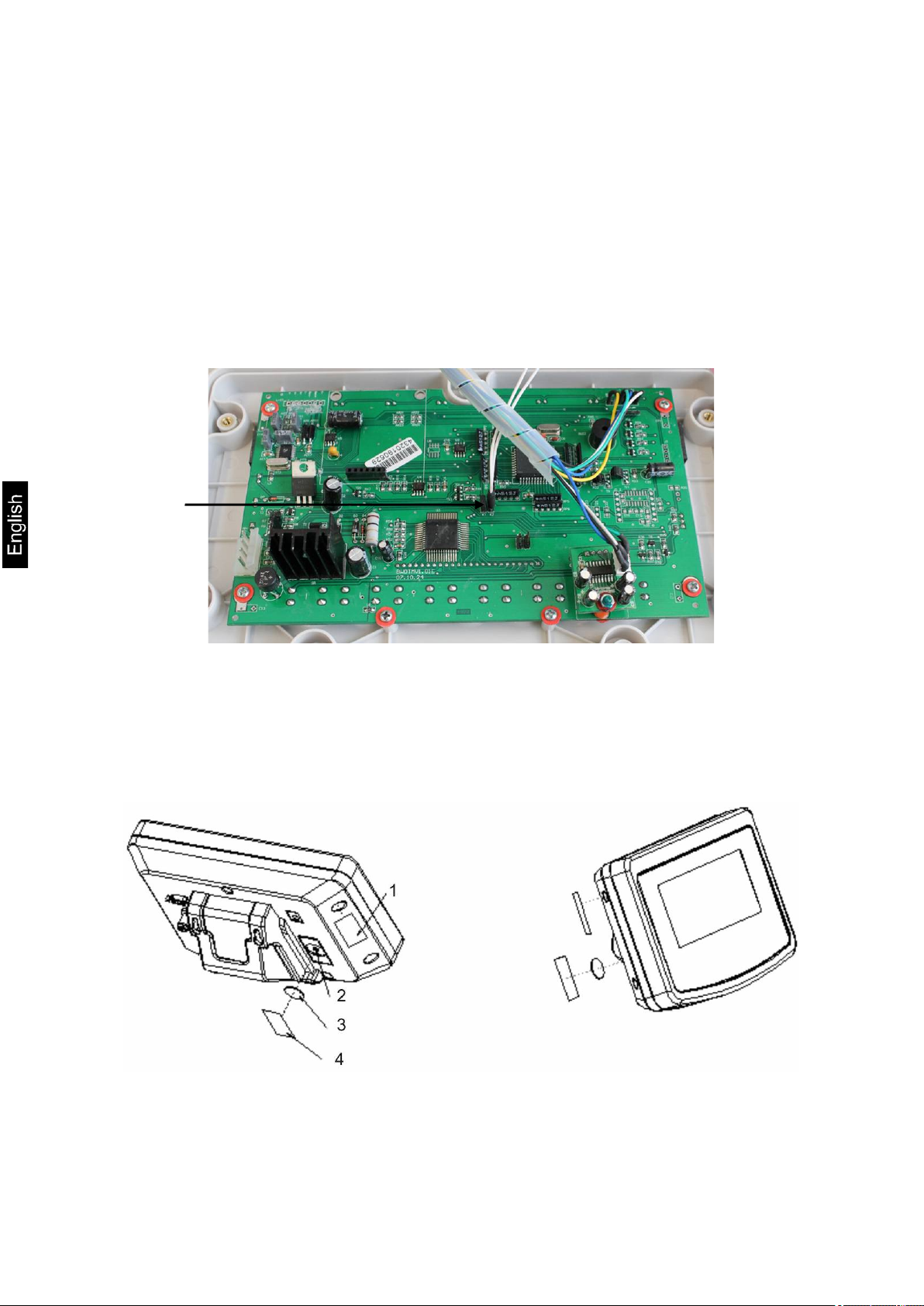
[K1]
Notes on verified weighing systems
KFB-TM:
Access to conductor plate:
• Remove seal
• Open display unit
• The application of the display unit as a weighing system able to be verified
requires that the contacts of the circuit board are short-circuited with the help
of a jumper [K1].
For non verifiable weighing systems remove the jumper.
In verified weighing systems the menu item for adjustment, „P2 mode“ will be
blocked.
To disable the access lock, destroy the seal and actuate the adjustment switch.
Position of seals and adjusting switch
1. Self-destroying seal mark
2. Adjustment switch
3. Cover of adjustment switch
4. Self-destroying seal mark
22 KFB/KFN-TM-BA_IA-e-1220
Page 23
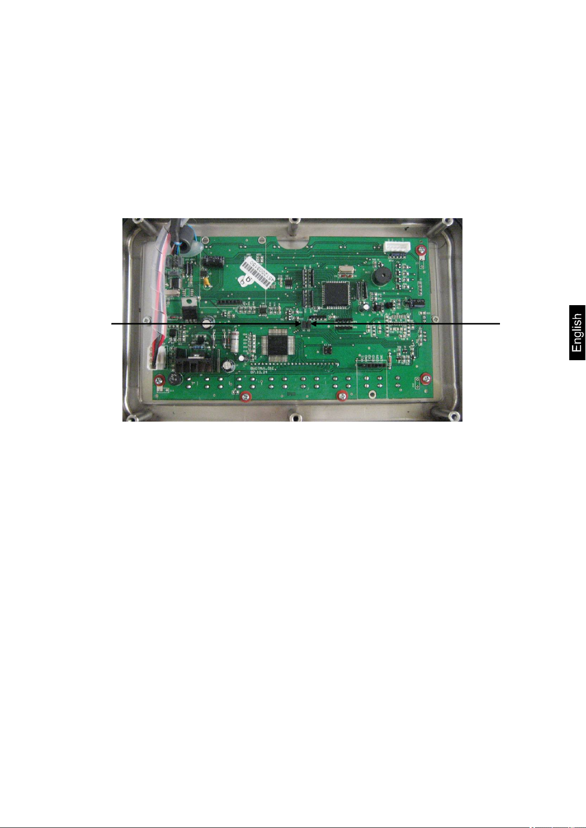
[K1]
[K2]
KFN-TM:
Access to conductor plate:
• Remove seal
• Open display unit
• The application of the display unit as a weighing system able to be verified
requires that the contacts of the circuit board are short-circuited with the help
of a jumper [K1]. For non verifiable weighing systems remove the jumper.
• To adjust, short-circuit the contacts of the circuit board, using a jumper [K2].
KFB/KFN-TM-BA_IA-e-1220 23
Page 24
exceeding the stated maximum load (max) of the device, minus a
7 Operation
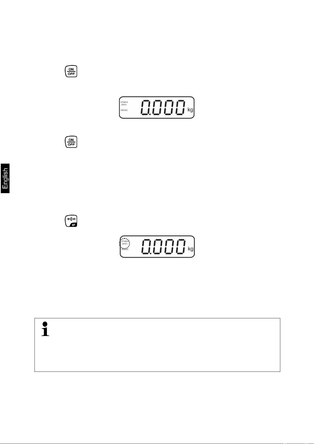
7.1 Start-up
Press and the instrument will carry out a self-test. As soon as the weight
display appears, the instrument will be ready to weigh.
7.2 Switching Off
Press and the display will disappear.
7.3 Zeroing
Resetting to zero corrects the influence of light soiling on the weighing plate. The unit
is equipped with an automatic zero setting function. Therefore the unit can be reset to
zero at any time as follows:
To unload the weighing system
Press and zero display as well as indicator ZERO will appear.
7.4 Simple weighing
Place goods to be weighed on balance.
Wait until stability display STABLE appears.
Read weighing result.
Overload warning
Overloading
possibly existing tare load, must be strictly avoided. This could damage the
instrument.
Exceeding maximum load is indicated by the display of „----“ and an audio
sound. Unload weighing system or reduce preload.
24 KFB/KFN-TM-BA_IA-e-1220
Page 25
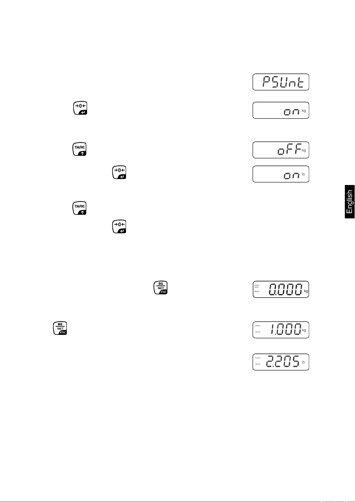
7.5 Switch-over weighing unit (only not verifiable weighing systems)
How to enable weighing units:
Call-up menu item P5 Unt, see chap. 8.1
Press and the first weighing unit with the current setting
will be displayed.
To enable [on] / disable [off] the displayed weighing unit,
press
Acknowledge with . The next unit with the current setting
will be displayed.
To enable [off] / disable [on] the displayed weighing unit,
press .
Acknowledge with .
Repeat sequence for each weighing unit.
Note:
„tj“ and „Hj“ cannot be activated at the same time, only either
... or ... .
Return to weighing mode using
Switch-over weighing unit:
Keep pressed, the display changes over to the
weighing units activated before (e.g. kg lb)
KFB/KFN-TM-BA_IA-e-1220 25
Page 26

7.6 Weighing with tare
Deposit weighing vessel. After successful standstill control press the button.
Zero display and indicator NET appear.
The weight of the container is now internally saved.
Weigh the material, the net weight will be indicated.
The weight of the weighing container will be displayed as a minus number after
removing the weighing container.
The tare procedure can be repeated as many times as necessary, for example
with initial weighing of several components for a mix (add-on weighing). The limit
is reached when the taring range capacity (see type plate)is full.
To change between gross weight and net weight, press .
To delete the tare value, remove load from weighing plate and press .
7.7 Weighing with tolerance range
You can set an upper or lower limit when weighing with tolerance range and thus
ensure that the weighed load remains exactly within the set limits.
During tolerance tests such as dosing, portioning and sorting the unit will indicate
exceeded or undershot limits by emitting an optical or acoustic signal.
Audio signal:
The acoustic signal depends on the settings in menu block „BEEP“.
Options:
• no
• ok
• ng
Acoustic signal turned off
An acoustic signal sounds when load is within tolerance
limits
An acoustic signal sounds when load is beyond tolerance
limits
26 KFB/KFN-TM-BA_IA-e-1220
Page 27

Optical signal:
Three colour signal lights indicate whether the load is within the two tolerance limits.
The signal lights provide the following information:
+
The settings for tolerance weighing may be called up either via menu block „P0 CHK“
(see chap. 8) or faster via the key combination
Settings
Goods to be weighed above tolerance limit
Goods to be weighed within tolerance range
Goods to be weighed below tolerance limit
-
Red signal light
glowing
Green signal light
glowing
Red signal light
glowing
Press and at the same time in weighing mode.
Press until the display for entering the lower limit value
appears.
Press , current setting will be displayed.
To enter the lower limit, e. g. 1000 Kg, press the navigation
keys (See chap. 2.1.1); the currently enabled digit will be
flashing.
Confirm input by .
Use to select
KFB/KFN-TM-BA_IA-e-1220 27
Page 28

Press and the current setting for the upper limit will be
displayed.
Press the navigation keys (See chap. 2.1.1) to enter the
upper limit, e.g. 1,100 kg; the currently enabled digit will be
flashing.
Confirm input by .
Use to select
Press and the current setting for the acoustic signal will
be shown.
Select desired setting (no, ok, ng) by .
Confirm input by .
Press repeatedly; weighing system is in tolerance
weighing mode. From here evaluation takes place whether
the goods to be weighed are within the two tolerance limits.
Weighing with tolerance range
Tare when using a weighing container
Put on goods to be weighed, tolerance control is started The signal lights
indicate whether the load is within the two set limits.
Load below specified
tolerance
Red signal light
next to „-“ ON illuminated
• The tolerance control is not active when the weight is under 20d.
• To delete limits, enter “00.000 kg“.
Load within specified
tolerance
Green signal light
next to „„ illuminated
Load exceeds specified
tolerance
Red signal light
next to „+“ ON illuminated
28 KFB/KFN-TM-BA_IA-e-1220
Page 29

• Menu setting:
• The totalizing function is not active when the weight is under 20d.
7.8 Manual totalizing
With this function the individual weighing values are added into the summation
memory by pressing and edited, when an optional printer is connected.
„P1 COM“ or „P2 COM“ „MODE“ „PR2““, see chap. 8
Add up:
Place weighing goods A.
Wait until the stability display STABLE appears, then press . The weight value
will be saved and printed if an optional printer is connected.
Remove the weighed good. More weighed goods can only be added when the
display ≤ zero.
Place goods to be weighed B.
Wait until the stability display appears, then press . Weighing value will be
added to summation memory and possibly printed.
The number of weighing actions, followed by the total weight will be displayed for
2 sec.
Add more weighed goods as described before.
Please note that the weighing system must be unloaded between the individual
weighing procedures.
This process may be repeated 99 times or till such time as the capacity of the
weighing system has been exhausted.
Display of the saved weighing data:
Press , number of weighing, followed by the total weight will be displayed for
2 sec. Press to print out this display.
KFB/KFN-TM-BA_IA-e-1220 29
Page 30

Menu setting
Menu setting
Delete weighing data:
Press and at the same time The data in the summation memory are
deleted.
Printout example KERN YKB-01N, verified weighing system:
„P1 COM“ or „P2 COM“ „Lab 2“ / Prt 7“
„P1 COM“ or „P2 COM“ „Lab 0“ / Prt 0“
1 First weighing
2 Second weighing
3 Third weighing
4 Number of weighings / total
+
30 KFB/KFN-TM-BA_IA-e-1220
Page 31

• Menu settings:
7.8.
7.9 Automatic adding-up
With this function the individual weighing values are automatically added into the
summation memory when the balance is unloaded without pressing and edited,
when an optional printer is connected.
„P1 COM“ or „P2 COM „MODE“ „AUTO““, see chap. 8
Der Indikator AUTO wird angezeigt.
Add up:
Place weighing goods A.
After the standstill control sounds a signal tone. The weighing value will be added
to the summation memory and printed.
Remove the weighed good. More weighed goods can only be added when the
display ≤ zero.
Place goods to be weighed B.
After the standstill control sounds a signal tone. The weighing value will be added
to the summation memory and printed. Number of weighing, followed by the total
weight will be displayed for 2 sec.
Add more weighed goods as described before.
Please note that the weighing system must be unloaded between the individual
weighing procedures.
This process may be repeated 99 times or till such time as the capacity of the
weighing system has been exhausted.
Display and delete the weighing data, as well as printout examples see chap.
KFB/KFN-TM-BA_IA-e-1220 31
Page 32

7.10 Parts c ounti ng
Before the balance can count parts, it must know the average part weight (i.e.
reference). Proceed by putting on a certain number of the parts to be counted. The
balance determines the total weight and divides it by the number of parts, the socalled reference quantity. Counting is then carried out on the basis of the calculated
average piece weight.
As a rule:
The higher the reference quantity the higher the counting exactness.
In weighing mode , press and hold until the message „P
10“ appears that is used to set the reference quantity.
Use to set the desired reference quantity (such as 100),
options include P 10, P 20, P 50, P100, P 200.
Place as many items to be counted (such as 100 items) as
demanded by the set reference quantity and confirm by
The weighing scales calculate the reference weight. The
current quantity (such as 100 items) will be displayed.
Remove reference weight. The balance is from now in parts
counting mode counting all units on the weighing plate.
Back to Weighing mode by .
32 KFB/KFN-TM-BA_IA-e-1220
Page 33

7.11 Animal weighing
The animal weighing function is suitable for weighing restless loads.
The weighing system will display a mean value derived from several weighing results.
The animal weighing program can be enabled by either calling up menu block
„P3 OTH“ or „P4 OTH“ „ANM“ „ON“ (See chap. 8) or faster via key combination.
The indicator shows HOLD as long as the animal weighing function remains enabled.
Place the load on the weighing system and wait until the scale is steady.
Press and at the same time; you will hear an acoustic signal, indicating
that the animal weighing function is enabled.
Whilst averaging is taking place you can add or remove loads as the measuring
value will be constantly updated.
To deactivate the animal weighing function press and at the same time.
KFB/KFN-TM-BA_IA-e-1220 33
Page 34

7.12 Lock keyboard
To enable/disable the keyboard lock go to menu item „P3 OTH“ or „P4 OTH“
„LOCK“, see chap.8.
Whilst the function is enabled the keyboard will self-lock after no key has been
pressed for 10 minutes. „K-LCK“ will be displayed as soon as a key is pressed.
To disable the lock, press , and hold plus (2 s) until „U LCK“ appears.
7.13 Display background illumination
Keep pressed (3s) until „setbl“ appears.
Press again, the current setting will be displayed.
Use to select the desired setting.
bl on Continuous background lighting
bl off Background illumination off
bl Auto Automatic background illumination on when weighing pate is
loaded or key pressed.
Either save by or cancel by pressing .
Back to weighing mode by .
34 KFB/KFN-TM-BA_IA-e-1220
Page 35

7.14 Automatic switch-off function „AUTO OFF“
The unit is automatically switched off within the preset time when the display unit or
the weighing bridge are not operated.
Keep pressed (3s) until „setbl“ appears.
Press to call up AUTO OFF-function
Press , the current setting will be displayed.
Use to select the desired setting.
of 0 AUTO OFF - function disabled
of 3 Weighing system will be turned off after 3 min.
of 5 Weighing system will be turned off after 5 min.
of 15 Weighing system will be turned off after 15 min.
of 30 Weighing system will be turned off after 30 min.
Either save by or cancel by pressing .
Back to weighing mode by .
KFB/KFN-TM-BA_IA-e-1220 35
Page 36

current setting will be displayed.
8 Menu
The application of the display unit as a verified weighing system requires that you
short-circuit the two contacts [K1] of the circuit board, using a jumper. To that effect,
a menu for verified weighing systems is available. For menu layout see chap. 8.2.
There is no jumper for weighing systems that cannot be verified. To that effect, a
menu is available for weighing systems that cannot be verified, Menu layout
see chap. 8.1
Navigation in the menu:
Call up menu
Switch-on balance and during the selftest press .
Press , , subsequently, the first menu
block „PO CHK“ will be displayed.
Select menu block
Select setting
Change settings
Acknowledge setting /
exit the menu
Return to weighing
mode
With help of , the individual menu items can be
selected one after the other.
Confirm selected menu item by pressing . The
To change to the available settings, press the
navigations keys as described in chap. 2.1.
Either save by pressing or cancel by pressing .
Press repeatedly to exit menu.
36 KFB/KFN-TM-BA_IA-e-1220
Page 37

Menu block
Main menu
Menu item
Submenu
Acoustic signal for weighing with tolerance range
switched off
P1 REF
P2 COM
MODE
CONT
Continuous data output
ST1
One output for stable weighing value
STC
Continuous data output of stable weighing
values
PR1
Output after pressing
PR2
Manual totalizing, see chap. 7.8.
added to the summation memory and issued.
AUTO*
For automatic add-up see chap. 7.9.
memory on unloading of weighing scale.
wirel
kit 1
BAUD
Available Baudrate: 600, 1200, 2400, 4800, 9600*
8.1 Overview non verifiable weighing systems
(contacts of circuit board [K1] not short-circuited)
Available settings / explanation
PO CHK
Weighing with
tolerance range,
see chap. 7.7
Zero point
settings
SET H Upper limit value, input see chap. 7.7
SET LO Lower limit value, input see chap. 7.7
PCS H Not documented
PCS L Not documented
BEEP no
ok Audio sound when load is within tolerance limits
nG Audio sound when load is beyond tolerance limits
A2n0 Automatic zero point correction (Autozero) by changing the
display, digits selectable (0.5d, 1d, 2d, 4d)
0AUto Zero setting range
Load range where the display after switching-on the
balance is set to zero. Selectable 0, 2, 5, 10, 20, 50, 100
%
0rAGE Zero setting range
Load range where the display is set to zero by pressing
. Selectable 0, 2, 4, 10 , 20* , 50, 100%.
0tArE Automatic taring „on / off“, taring range adjustable in menu
item „0Auto“.
SPEEd Not documented
Zero Zero point setting
Interface
parameter
ASK
Press and the weighing value will be
This function is used to issue and add individual
weighing values automatically to the summation
For remote control commands, see chap. 10.4
Not documented
KFB/KFN-TM-BA_IA-e-1220 37
Page 38

Pr
7E1
7 bits, even parity
7o1
7 bits, odd parity
8n1*
8 bits, no parity
PTYPE
tPUP*
Standard printer setting
LP50
Not documented
Lab
Lab x
(Lab 0*)
Prt
Prt x
(Prt 0*)
LAnG
eng*
Standard settings English
chn
P3 CAL
COUNT
Display internal resolution
DECI
Position of the decimal dot
DUAL
Setting balance type, capacity (Max) and readability (d)
off
Single-range balance
R1 inc
Readability
R1 cap
Capacity
on
Dual range balance
R1 inc
Readability 1st weighing range
R1 cap
Capacity 1st weighing range
R2 inc
Readability 2nd weighing range
R2 cap
Capacity 2nd weighing range
CAL
noLin
For adjustment, see chap. 6.9.2
Liner
For linearization, see chap. 6.10.2
GrA
Not documented
on
Keyboard lock enabled, see chap. 7.11
off*
Keyboard lock disabled
on
Animal weighing enabled, see chap. 7.10
off*
Animal weighing disabled
kg
on* off
g on off*
lb
on off*
oz
on off*
tJ
on off
HJ
on off
Configuration
data
see chap. 12.4
For data output format, see chap.8.2, tab. 1
P4 OTH
LOCK
ANM
P5 Unt
Switch-over
weighing unit,
see chap. 7.5
P6 xcl Not documented
P7 rst
Use to reset balance settings to factory default.
P8 uwb Not documented
Factory settings are marked by *.
38 KFB/KFN-TM-BA_IA-e-1220
Page 39

Menu block
Main menu
Menu item
Submenu
Acoustic signal for weighing with tolerance
range switched off
Audio sound when load is within tolerance
limits
Audio sound when load is beyond tolerance
limits
8.2 Overview verified weighing systems
(contacts of circuit board [K1] short-circuited by means of jumper)
In verified weighing systems the access to „P2 mode and „P4 tAr“ is locked.
KERN KFB-TM:
To disable the access lock, destroy the seal and actuate the adjustment switch.
Position of the adjustment switch see chap. 6.11.
KERN KFN-TM:
In order to unlock the access, the seal must be destroyed and both contacts of the
printed circuit board [K2] must be short-circuited by a jumper, see chap. 6.11.
Attention:
After destruction of the seal the weighing system must be re-verified by an
authorised agency and a new verification wire/seal mark fitted before it can be
reused for applications subject to verification.
PO CHK
Weighing with
tolerance range,
see chap. 7.7
SET H
SET LO
PCS H Not documented
PCS L Not documented
BEEP
Available settings / explanation
Upper limit value, input see chap. 7.7
Lower limit value, input see chap. 7.7
no
ok
ng
KFB/KFN-TM-BA_IA-e-1220 39
Page 40

P1 COM
MODE
CONT
Continuous data output
ST1
One output for stable weighing value
STC
Continuous data output of stable weighing
values
PR1
Output after pressing
PR2
Manual totalizing, see chap. 7.8
added to the summation memory and issued.
AUTO
ASK
For remote control commands, see chap. 10.4
baud
Available Baudrate: 600, 1200, 2400, 4800, 9600
Pr
7E1
7 bits, even parity
7 bits, odd parity
8 bits, no parity
PtYPE
Standard printer setting
Not documented
Lab
Prt
Interface
parameter
Press and the weighing value will be
For automatic totalizing see chap. 7.9
This function is used to issue and add
individual weighing values automatically to the
summation memory on unloading of weighing
scale.
7o1
8n1
tPUP
LP50
Lab x
Details see following table 1
Prt x
40 KFB/KFN-TM-BA_IA-e-1220
Page 41

P2 mode
SiGr
Single-range balance
COUNT
Display internal resolution
DECI
Position of the decimal dot
Div.
Readability [d] / verification value[s]
CAP
Balance capacity [Max]
noLin
Adjustment, see chap. 6.9
LinEr
Linearisation, see chap. 6.10
GrA
Not documented
dUAL 1
Dual range balance
scales will remain in 2nd range.
COUNT
Display internal resolution
DECI
Position of the decimal dot
Readability [d] / verification value [e]
1. weighing range
Readability [d] / verification value [e]
2. weighing range
Weighing scale capacity [max]
1. Weighing range
Weighing scale capacity [max]
2. Weighing range
noLin
Adjustment, see chap. 6.9
LinEr
For linearization, see chap. 6.10
GrA
Not documented
dUAL 2
Multi-interval balance
changed during loading and unloading.
COUNT
Display internal resolution
DECI
Position of the decimal dot
Readability [d] / verification value [e]
1. weighing range
Readability [d] / verification value [e]
2. weighing range
Weighing scale capacity [max]
1. Weighing range
Weighing scale capacity [max]
2. Weighing range
noLin
Adjustment, see chap. 0
LinEr
Linearisation, see chap. 6.10
GrA
Not documented
P3 OTH
on
Keyboard lock enabled
off
Keyboard lock disabled
on
Animal weighing enabled
off
Animal weighing disabled
P4 tAr
Confirm input by .
Konfigurationsdaten
CAL
Balance with two weighing ranges and different maximum load
and weighing ranges and interval sizes but only one loadsupporting pan, whereby each range extends from zero to the
respective maximum capacity. When load is removed, weighing
div 1
div.
div 2
CAP 1
CAP
CAP 2
CAL
Weighing scales with one weighing range subdivided into partial
weighing ranges, each providing a different scale interval. The
scale interval depends on the applied load and is automatically
div 1
div.
div 2
CAP 1
CAP
CAP 2
CAL
LOCK
s. Kap. 7.10 / 7.11
ANM
Restricted taring
range
KFB/KFN-TM-BA_IA-e-1220 41
Press , the current setting will be displayed. Using the
navigation buttons (see chap. 2.1.1) select the desired setting, the
active digit is flashing.
Page 42

NT:
0.666 kg
GS:
0.222 kg
NT:
TOTAL:
0.222 kg
0.222 kg
NT:
0.666 kg
GS:
0.222 kg
NT:
TOTAL:
0.222 kg
0.444 kg
NT:
0.666 kg
GS:
0.222 kg
NT:
TOTAL:
0.222 kg
0.666 kg
GS:
0.888 kg
NT:
0.666 kg
GS:
0.222 kg
NT:
TOTAL:
0.222 kg
0.888 kg
NO:
4
NO:
4
NO:
TOTAL:
4
1.000 kg
NO:
5
NO:
5
NO:
5
NO:
TOTAL:
5
1.222 kg
NO:
6
NO:
6
NO:
6
NO:
TOTAL:
6
1.444 kg
NO:
7
NO:
7
NO:
7
NO:
TOTAL:
7
1.666 kg
GS / GW
Gross weight
NT
Net weight
TW
Tare weight
NO
Number weighing processes
TOTAL
Total of all individual weighings
Tab. 1. Printout examples
Lab
0 1 2 3
pr
0
1
2
3
4
5
GS: 0.888 kg
GS: 0.888 kg
GS:
NO:
GS:
GS:
11/11/11
0.888 kg
4
0.888 kg
0.888 kg
TW:
GW:
TW:
GW::
TW:
GW::
TW:
GW::
NT:
TW:
GW::
NT:
TW:
GW::
0.222 kg
0.888 kg
0.222 kg
0.888 kg
0.222 kg
0.888 kg
0.222 kg
0.888 kg
0.666 kg
0.222 kg
0.888 kg
0.666 kg
0.222 kg
0.888 kg
TOTAL:
TOTAL:
TOTAL:
TOTAL:
GS:
TOTAL:
GS:
TOTAL:
0.222 kg
0.444 kg
0.666 kg
0.888 kg
0.222 kg
1.000 kg
0.222 kg
1.222 kg
TW:
GW:
TW:
GW:
TW:
GW:
TW:
GW:
NT:
TW:
GW:
NT:
TW:
GW:
0.666 kg
0.888 kg
0.666 kg
0.888 kg
0.666 kg
0.888 kg
0.666 kg
0.888 kg
0.222 kg
0.666 kg
0.888 kg
0.222 kg
0.666 kg
0.888 kg
6
7
GS:
GS:
0.888 kg
0.888 kg
NT:
TW:
GW::
NT:
TW:
GW::
0.666 kg
0.222 kg
0.888 kg
0.666 kg
0.222 kg
0.888 kg
GS:
TOTAL:
GS:
TOTAL:
0.222 kg
1.444 kg
0.222 kg
1.666 kg
NT:
TW:
GW:
NT:
TW:
GW:
0.222 kg
0.666 kg
0.888 kg
0.222 kg
0.666 kg
0.888 kg
42 KFB/KFN-TM-BA_IA-e-1220
Page 43

Value outside the A/D changer
9 Service, maintenance, disposal
9.1 Clean
• Before cleaning, disconnect the appliance from the operating voltage.
• Do not use aggressive detergents (solvents or similar).
9.2 Service, maintenance
The appliance may only be opened by trained service technicians who are authorized
by KERN.
Before opening, disconnect from power supply.
9.3 Disposal
Disposal of packaging and appliance must be carried out by operator according to
valid national or regional law of the location where the appliance is used.
9.4 Error messages
Error
message
Description Possible causes
- - - - -
Maximum load exceeded
- - ol - -
Err 1
Err 2
Err 4 Zeroing range exceeded due
Err 5 Keyboard error
Err 6
Incorrect data input
Incorrect time entry
to switching-on balance or
pressing (normally 4%
max)
range
• Unload weighing system or reduce
preload.
• Follow format “yy:mm:dd“
• Follow format “hh:mm:ss“
• Object on the weighing plate
• Overload when zeroing
• Weighing plate not installed
• Damaged weighing cell
Err 9 Stability display does not
appear
KFB/KFN-TM-BA_IA-e-1220 43
• Damaged electronics
• Check the environmental
conditions.
Page 44

Err 10 Communication error
Err 15 Gravitation error
Err 17 Taring range exceeded
Fai l h /
Fai l l
Err P
Ba lo /
Lo ba
Should other error messages occur, switch balance off and then on again. If the error
message remains inform manufacturer.
Adjustment error
Printer error
Battery very low
• No data
• Range 0.9 ~ 1.0
• Reduce load
• Repeat adjustment.
• Check communication parameters
• Recharge battery
44 KFB/KFN-TM-BA_IA-e-1220
Page 45

Pin 5 signal earth
10 Da t a out put RS 2 32C
You can print weighing data automatically via the RS 232C interface or manually by
pressing via the interface according to the setting in the menu.
This data exchange is asynchronous using ASCII - Code.
The following conditions must be met to provide successful communication between
the weighing system and the printer.
• Use a suitable cable to connect the display unit to the interface of the printer.
Faultless operation requires an adequate KERN interface cable.
• Communication parameters (baud rate, bits and parity) of display unit and
printer must match. For a detailed description of interface parameters see
chap. 8, menu block „P1 COM“ or ‚“P2 COM“
10.1 Technic al da ta
Connection 9 pin d-subminiature bushing
Pin 2 input
Pin 3 output
Baud rate 600/1200/2400/4800/9600 may be selected
Parity 8 bits, no parity / 7 bits, even parity / 7 bits, odd parity
KFB/KFN-TM-BA_IA-e-1220 45
Page 46

ST
Stable value
US
Instable value
GS
Gross weight
NT
Net weight
<lf>
Space line
<lf>
Space line
ST, GS 1.000kg
****************************
10.2 Printer mode
Printout examples (KERN YKB-01N):
• Weighing
• Counting
10.3 Output log
Weighing mode
10.4 Remote control instructions
PCS 100
****************************
HEADER1: ST=STABLE, US=UNSTABLE
HEADER2: NT=NET, GS=GROSS
Command Significance
T <CR><LF> Taring
Z <CR><LF> Zeroing
W <CR><LF> Send all weighing details
S <CR><LF> Send stable weight value
P <CR><LF> Piece counting
46 KFB/KFN-TM-BA_IA-e-1220
Page 47

The displayed weight does
not glow.
• Mains power supply interrupted (mains cable
defective).
• Power supply interrupted.
• (Rechargeable) batteries are inserted incorrectly or
empty
• No (rechargeable) batteries inserted.
The displayed weight is
• Table/floor vibrations
• Weighing pan has contact with other objects.
possible)
The weighing result is
obviously incorrect
• Adjustment is no longer correct.
• Great fluctuations in temperature.
possible)
11 Instant help
In case of an error in the program process, briefly turn off the display unit and
disconnect from power supply. The weighing process must then be restarted from the
beginning.
Help:
Fault Possible cause
• The display unit is not switched on.
permanently changing
Should other error messages occur, switch display unit off and then on again. If the
error message remains inform manufacturer.
• Draught/air movement
• Electromagnetic fields / static charging (choose
different location/switch off interfering device if
• The display of the balance is not at zero
• Warm-up time was ignored.
• Electromagnetic fields / static charging (choose
different location/switch off interfering device if
KFB/KFN-TM-BA_IA-e-1220 47
Page 48

12 Installing displa y unit / weighi ng bridge
• Installation / configuration of a weighing system must be carried out
12.1 Technic al da ta
Supply voltage: 5 V/150mA
Max. signal voltage 0-10 mV
Zeroing range 0-2 mV
Sensitivity 2-3 mV/V
Resistance parameter 80 - 100 Ω, max 4 items per 350 Ω load cell
by a well acquainted specialist with the workings of weighing
balances.
12.2 Weighing system design
The display unit is suitable for connection to any analogue platform in compliance
with the required specifications.
The following data must be established before selecting a weighing cell:
• Weighing balance capacity
This usually corresponds to the heaviest load to be weighed.
• Preload
This corresponds to the total weight of all parts that are to be placed on the
weighing cell such as upper part of platform, weighing pan etc.
• Total zero setting range
This is composed of the start-up zero setting range (± 2%) and the zero
setting range available to the user via the ZERO-key (2%). The total zero
setting range equals therefore 4 % of the scale’s capacity.
The addition of weighing scales capacity, preload and the total zero setting
range give the required capacity for the weighing cell.
To avoid overloading of the weighing cell, include an additional safety
margin.
• Smallest desired display division
• Verifiability, if required
The application of the display unit as a verified weighing system requires
that you short-circuit the two contacts [K1] of the circuit board, using a
jumper; for position see chap. 6.11.
Remove the jumper for weighing systems not able to be verified.
48 KFB/KFN-TM-BA_IA-e-1220
Page 49

12.3 How to connect the platform
Disconnect the display unit from the power supply.
Solder the individual leads of the load cell cable onto the circuit board. See
diagram below.
Please see diagram below for plug allocation.
Use the connecting cable to connect the platform to the display unit, see chap. 2,
item [7]. Tighten the coupling ring.
KFB/KFN-TM-BA_IA-e-1220 49
Page 50

12.4 Configure displ ay unit
12.4.1 Verified weighing systems
(contacts of circuit board [K1] short-circuited by means of jumper)
For menu overview see chap. 8.2.
In verified weighing systems the menu item for calibration „P2 mode“ is blocked.
KERN KFB-TM:
To disable the access lock, destroy the seal and actuate the adjustment switch.
Position of the adjustment switch see chap. 6.11
KERN KFN-TM:
To override the blocked access you will have to destroy the seal before calling up the
menu and to short-circuit the two contacts on the circuit board [K2], using a jumper
(See chap. 6.11).
Attention:
After destruction of the seal the weighing system must be re-verified by an
authorised agency and a new verification wire/seal mark fitted before it can be
reused for applications subject to verification.
Call up menu:
Switch-on balance and during the selftest press .
Press , , subsequently, the first menu block
„PO CHK“ will be displayed.
Press repeatedly until „P2 mode“ will be displayed.
Operate the adjustment switch (models KFB-TM).
Press and use to select the weighing scales type.
Single-range balance
Dual range balance
Multi-interval balance
50 KFB/KFN-TM-BA_IA-e-1220
Page 51

Example single range scales (d = 10 g, max. 30 kg)
Confirm selected weighing scales type by pressing ; the
first menu item „COUNT“ will be shown.
1. Display internal resolution
Press , the internal resolution will be shown.
Return to menu by .
Press to select the next menu item.
2. Position decimal point
Press , the currently set position of the decimal dot is
displayed.
Press to select the desired setting.
Options 0, 0.0, 0.00, 0.000, 0.0000.
Confirm input by .
Press to select the next menu item.
3. Readability
Press and current setting will be displayed.
Select desired setting by .
Options 1, 2, 5, 10, 20, 50.
Confirm entry by .
Press to select the next menu item.
KFB/KFN-TM-BA_IA-e-1220 51
Page 52

6.10.1 for linearisation
4. Capacity
Press , the current setting will be displayed.
Using the navigation buttons (see chap. 2.1.1) select the
desired setting, the active digit is flashing.
Confirm input by .
Press to select the next menu item.
5. Adjustment / linearization
Adjustment or linearization is required after entering
configuration data.
For carrying out adjustment see chap. 6.9.1/step 6 or chap.
52 KFB/KFN-TM-BA_IA-e-1220
Page 53

Example dual range scales (d = 2 / 5 g, max. 6 / 15 kg)
Confirm selected weighing scales type by ; the first
menu item „COUNT“ will be shown.
1. Display internal resolution
Press , the internal resolution will be shown.
Return to menu by .
Press to select the next menu item.
2. Position decimal point
Press , the currently set position of the decimal dot is
displayed.
Use to select the desired setting.
Options 0, 0.0, 0.00, 0.000, 0.0000.
Confirm input by .
Press to select the next menu item.
KFB/KFN-TM-BA_IA-e-1220 53
Page 54

3. Readability
Press , the display used to enter readability/verification
value for first weighing range will appear.
Press , the current setting will be displayed.
Select desired setting with and acknowledge by .
Press to enter the next menu item for
readability/verification value for second weighing range.
Press and current setting will be displayed.
Select desired setting with and acknowledge by .
Press , the unit will return to the menu
Press to select the next menu item.
54 KFB/KFN-TM-BA_IA-e-1220
Page 55

6.10.1 for linearisation
4. Capacity
Press and the display for entering the capacity for the
first weighing range will appear.
Press and current setting will be displayed.
Select desired setting with and acknowledge by .
Press to select the next menu item used to enter the
capacity for the second weighing range.
Press and current setting will be displayed.
Select desired setting with and acknowledge by .
Press , the unit will return to the menu
Use toselect next menu item.
5. Adjustment / linearization
Adjustment or linearization is required after entering
configuration data.
For carrying out adjustment see chap. 6.9.1/step 6 or chap.
Acknowledge using , the current setting is displayed.
Acknowledge by , select desired setting with
= Adjustment
= Linearisation
KFB/KFN-TM-BA_IA-e-1220 55
Page 56

Press repeatedly to exit menu.
12.4.2 Non verifiable weighing systems
(contacts of circuit board [K1] not short-circuited )
+ For menu overview see chap. 8.1.
Call up menu
Switch-on balance and during the selftest press .
Press , , subsequently , the first menu block
„PO CHK“ will be displayed.
Press repeatedly until „CAL“ will be displayed.
Press , the first menu item „COUNT“ will be displayed.
Navigation in the menu
With help of , the individual menu items can be
selected one after the other.
Confirm selected menu item by pressing . The current
setting will be displayed.
To change to the available settings, press the navigations
keys as described in chap. 2.1.1.
Either save by pressing or cancel by pressing .
56 KFB/KFN-TM-BA_IA-e-1220
Page 57

Parameter selection
1. Display internal resolution
Press , the internal resolution will be shown.
Return to menu by .
Use to select another menu item.
2. Position decimal point
Press , the currently set position of the decimal dot is
displayed.
To make changes using the navigation keys (See chap.
2.1.1), select the desired setting. Options 0, 0.0, 0.00,
0.000, 0.0000.
Confirm input by .
Use to select another menu item.
3. Weighing scales type, capacity and readability
Press and current setting will be displayed.
Select desired setting by .
„off“ Single-range balance
„on“ Dual range balance
Press to confirm, the display for entering readability (for
dual range scales for the first weighing range) appears.
Press , the current setting will be displayed.
KFB/KFN-TM-BA_IA-e-1220 57
Page 58

the current setting will be shown (such as max. =
Select desired setting with and acknowledge by .
Press , the display for entering capacity will appear (at
dual range balance for the first range).
Press ,
2000kg).
Using the navigation buttons (see chap. 2.1.1) select the
desired setting, the active digit is flashing.
Acknowledge with .
In a single-range balance the entry of capacity / readability
is finished.
either in single-range balance
Press , the unit will return to the menu Press to call
up next menu item „CAL“.
or
In a dual range balance enter readability/verification value
and capacity of the second weighing range.
Press , the display for entering the capacity of the
second weighing range will appear.
Press , the current setting will be displayed.
Using the navigation buttons (see chap. 2.1.1) select the
desired setting, the active digit is flashing.
Confirm input by .
58 KFB/KFN-TM-BA_IA-e-1220
Page 59

6.10.2 for linearisation
Press , the display for entering the readability of the
second weighing range will appear.
Press , the current setting will be displayed.
Select desired setting with and acknowledge by .
Press , the unit will return to the menu
Press to call next menu item.
4. Adjustment or linearisation
Adjustment or linearisation is required after entering
configuration data.
For carrying out adjustment see chap. 6.9.2/step 4 or chap.
Acknowledge using , the current setting is displayed.
Press to confirm, press to select the desired
setting
noLin = Adjustment
LineAr = Linearisation
KFB/KFN-TM-BA_IA-e-1220 59
Page 60

KERN & Sohn GmbH
D-72322 Balingen-Frommern
Phone: 0049-[0]7433- 9933-0
D
Konformitätserklärung
Wir erklären hiermit, dass das Produkt, auf das sich diese Erklärung bezieht,
mit den nachstehenden Normen übereinstimmt.
EN
Declaration of
conformity
We hereby declare that the product to which this declaration refers conforms
to the following standards.
CZ
Prohlášení o
shode
Tímto prohlašujeme, že výrobek, kterého se toto prohlášení týká, je v souladu
s níže uvedenými normami.
E
Declaración de
conformidad
Manifestamos en la presente que el producto al que se refiere esta
declaración está de acuerdo con las normas siguientes
F
Déclaration de
conformité
Nous déclarons avec cela responsabilité que le produit, auquel se rapporte la
présente déclaration, est conforme aux normes citées ci-après.
I
Dichiarazione di
conformità
Dichiariamo con ciò che il prodotto al quale la presente dichiarazione si
riferisce è conforme alle norme di seguito citate.
NL
Conformiteitverklaring
Wij verklaren hiermede dat het product, waarop deze verklaring betrekking
heeft, met de hierna vermelde normen overeenstemt.
P
Declaração de
conformidade
Declaramos por meio da presente que o produto no qual se refere esta
declaração, corresponde às normas seguintes.
PL
Deklaracja
zgodności
Niniejszym oświadczamy, że produkt, którego niniejsze oświadczenie dotyczy,
jest zgodny z poniższymi normami.
RUS
Заявление о
соответствии
Мы заявляем, что продукт, к которому относится данная декларация,
соответствует перечисленным ниже нормам.
EU Directive
Standards
2004/108/EC
EN55022: 2006 A1:2007
EN55024: 1998+A1:2001+A2:2003
2006/95/EC
EN 60950-1:2006
EN 60065:2002+A1:2006
2005/32/EC
Date: 13.10.2011
Signature:
KERN & Sohn GmbH
Management
KERN & Sohn GmbH, Ziegelei 1, D-72336 Balingen, Tel. +49-[0]7433/9933-0
Fax +49-[0]7433/9933-149, E-Mail: info@kern-sohn.com, Internet: www.kern-sohn.com
13 De c laration of Conformity / Type Approval Certificate /
Test Certificate
Postbox 4052
E-Mail: info@kern-sohn.de
Fax: 0049-[0]7433-9933-149
Internet: www.kern-sohn.de
Declaration of confor m ity
EC Declaration of Conformity EC-Declaration of -Conformity
EC- Déclaration de conformité EC-Declaración de Conformidad
EC-Dichiarazione di conformità EC-Conformiteitverklaring
EC- Declaração de conformidade EC- Prohlášení o shode
EC-Deklaracja zgodności EC-Заявление о соответствии
Electronic Balance:
KERN KFB-TM, KFN-TM, BFB, BFN, IFB, NFB, SFB, UFA, UFB, UFN
EN61000-3-3:1995+A1:2001+A2:2005
60 KFB/KFN-TM-BA_IA-e-1220
Page 61

VAT No. DK 12275110
EC Type-Approval Certificate
No. DK 0199.202 Revision 1
KFN-TM / KFB-TM / BFB / IFB / SFB / UFB / UFN / NFB /
BFN / NFN
NON-AUTOMATIC WEIGHING INSTRUMENT
Issued by DELTA Danish Electronics, Light & Acoustics
EU - Notified Body No. 0199
In accordance with the requirements for the non-automatic weighing instrument of
EC Council Directive 2009/23/EC.
Issued to Kern & Sohn GmbH
Ziegelei 1
D 72336 Balingen-Frommern
GERMANY
In respect of Non-automatic weighing instrument designated KFN-TM / KFB-TM / BFB /
IFB / SFB / UFB / UFN / NFB / BFN / NFN with variants of modules of load
receptors, load cells and peripheral equipment.
Accuracy class III and IIII
Maximum capacity, Max: From 1 kg up to 199 950 kg
Verification scale interval: e = Max / n
Maximum number of verification scale intervals: n = 6000 for single-interval
and n = 2×3000 for multi-range and multi-interval (however, dependent on
environment and the composition of the modules).
Variants of modules and conditions for the composition of the modules are set
out in the annex.
The conformity with the essential requirements in annex 1 of the Directive is met by the ap-
plication of the European Standard EN 45501:1992/AC:1993 and WELMEC 2.1:2001.
Note: This certificate is a revised edition which replaces previous revisions.
The principal characteristics and approval conditions are set out in the descriptive
annex to this certificate.
The annex comprises 14 pages.
DELTA
Danish Electronics,
Light & Acoustics
Venlighedsvej 4
2970 Hørsholm
Denmark
Tel. (+45) 72 19 40 00
Fax (+45) 72 19 40 01
www.delta.dk
Issued on 2011-12-19
Valid until 2019-12-07 Signatory: J. Hovgård
Page 62

Annex page 1 of 14
Certificate of EU type-approval no. DK 0199.202 rev.1
Descriptive annex
Contents Page
1. Name and type of instrument and modules 2
2. Description of the construction and function 2
2.1 Construction 2
2.2 Functions 3
3. Technical data 4
3.1 Indicator 4
3.2 Load receptors, load cells and load receptor supports 5
3.3 Composition of modules 6
3.4 Documents 6
4. Interfaces and peripheral equipment 6
4.1 Interfaces 6
4.2 Peripheral equipment 6
5. Approval conditions 6
5.1 Measurement functions other than non-automatic functions 6
5.2 Counting operation is not approved for NAWI 6
5.3 Totalised weight is not a legal value. 6
5.4 Compatibility of modules 7
6. Special conditions for verification 7
6.1 Composition of modules 7
7. Securing and location of seals and verification marks 7
7.1 Securing and sealing 7
7.2 Verification marks 7
8. Location of CE mark of conformity and inscriptions 8
8.1 Indicator 8
9. Pictures 9
10. Composition of modules - illustrated 14
Issued by DELTA
Page 63

Annex page 2 of 14
Certificate of EU type-approval no. DK 0199.202 rev.1
1. Name and type of instrument and modules
The weighing instrument is designated KFN-TM / KFB-TM / BFB / IFB / SFB / UFB / UFN / NFB /
BFN / NFN. It is a system of modules consisting of an electronic indicator, connected to a separate
load receptor and peripheral equipment such as printers or other devices, as appropriate. The instrument is a Class III or IIII, self-indicating weighing instrument with single-interval, multi-range or
multi-interval, an external AC mains adapter, and an internal rechargeable battery (optional).
The indicators consist of analogue to digital conversion circuitry, microprocessor control circuitry,
power supply, keyboard, non-volatile memory for storage of calibration and setup data, and a weight
display contained within a single enclosure.
The modules appear from the sections 3.1, 3.2.1 and 3.2.2; the principle of the composition of the
modules is set out in the sections 6.1 and 10.
2. Description of the construction and function
2.1 Construction
2.1.1 Indicator
The indicator is specified in section 3.1.
Enclosures and keyboard
The indicators are housed in an enclosure made of either ABS plastic (model KFB-TM / BFB / IFB /
UFB / NFB) or stainless steel (Model KFN-TM / SFB / UFN / BFN / NFN).
The front panels of the indicator comprise:
• An LCD display with appropriate state indicators and 5½ digits.
• A keyboard containing 6 keys used to enter commands or data into the weight indicator, plus a key
for turning the indicator on/off. Each key is identified with a name and/or pictograph.
Electronics
The instruments use a single printed circuit board, which contains all of the instrument circuitry. The
metrological circuitry for the models of weight indicator is identical.
All instrument calibration and metrological setup data are contained in non-volatile memory.
The power supply accepts an input voltage of 9 - 12 VDC from the external power adapter, with input
from 230 VAC 50 Hz. The indicator produces a load cell excitation voltage of 5 VDC.
2.1.2 Load receptors, load cells and load receptor supports
Set out in section 3.2.
2.1.3 Interfaces and peripheral equipment
Set out in section 4.
Issued by DELTA
Page 64

Annex page 3 of 14
Certificate of EU type-approval no. DK 0199.202 rev.1
2.2 Functions
The weight indicating instruments are microcontroller based electronic weight indicators that require
the external connection of strain gauge load cell(s). The weight information appears in the digital display located on the front panel and may be transmitted to peripheral equipment for recording, processing or display.
The primary functions provided are detailed below.
2.2.1 Display range
The weight indicators will display weight from –Max to Max (gross weight) within the limits of the
display capacity.
2.2.2 Zero-setting
Pressing the “ZERO” key causes a new zero reference to be established and ZERO annunciator to turn
on indicating the display is at the centre of zero.
Semi-automatic zero-setting range: ±2% of Max.
Automatic zero-tracking range: ±2% of Max.
Initial zero-setting range: ±10% of Max.
Zero-setting is only possible when the load receptor is not in motion.
2.2.3 Zero-tracking
The indicators are equipped with a zero-tracking feature which operates over a range of 4% of Max
and only when the indicator is at gross zero and there is no motion in the weight display.
2.2.4 Tare
The instrument models are provided with a semi-automatic subtractive tare feature activated using the
“TARE” key.
When the tare func tio n is a ctiv e , the “G/N” key will toggle the display between showing Net and
Gross value.
2.2.5 Printing
A printer may be connected to the optional serial data port. The weight indicator will transmit the current to the printer when the “PRINT” key is pressed.
The printing will not take place if the load receptor is not stable, if the gross weight is less than zero,
or if the weight exceeds Max.
2.2.6 Weighing unstable samples
The indicator has a function for weighing unstable samples. It is turned on/off by pressing the
“ZERO” and “TARE” keys simultaneously.
2.2.7 Display test
A self-test routine is initiated by pressing the on/off key to turn the instrument off, then pressing it
again to turn the instrument on. The test routine turns on and off all of the display segments and light
indicators to verify that the display is fully functional.
Issued by DELTA
Page 65

Annex page 4 of 14
Certificate of EU type-approval no. DK 0199.202 rev.1
2.2.8 Real time clock
If it is available in the instrument, the real time clock can be activated to get printout with day and
time information.
2.2.9 Operator information messages
The weight indicator has a number of general and diagnostic messages which are described in detail in
the user’s guide.
2.2.10 Software version
The software revision level is displayed during the power-up sequence of the instrument.
The approved software version is 1.07 and 1.08.
The software version 1.08 includes possibility of multi-range.
2.2.11 Totalisation
The indicator can be configured with a totalisation function, adding actual weight display values to the
memory when pressing “M+” key if the equilibrium is stable.
Pressing “MR” key displays the total accumulated weight.
Pressing “M+” and “MR” key will clear the totalised value.
2.2.12 Battery operation
The indicator can be operated from an internal rechargeable battery, if this option is installed.
3. Technical data
The KFN-TM / KFB-TM / BFB / IFB / SFB / UFB / UFN / NFB / BFN / NFN weighing instruments
are composed of separate modules, which are set out as follows:
3.1 Indicator
The indicators have the following characteristics:
Type: KFN-TM / KFB-TM / BFB / IFB / SFB / UFB / UFN / NFB
/ BFN / NFN
Accuracy class: III and IIII
Weighing range: Single-interval, multi-range (2 ranges) or multi-interval (2
partial intervals)
Maximum number of Verification
Scale Intervals: ≤ 6000 (class III), ≤ 1000 (class IIII) for single-interval
≤ 3000 (class III), ≤ 1000 (class IIII) for multi-range and
multi-interval
Maximum tare effect: -Max within display limits
Fractional fa ctor: p'i = 0.5
Minimum input voltage per VSI: 1 µV
Excitation voltage: 5 VDC
Circuit for remote sense: present on the model with 7-terminal connector
Minimum input impedance: 87 ohm
Maximum input impedance: 1600 ohm
Mains power supply: 9 - 12 VDC / 230 VAC, 50 Hz using external adapter
Operational temperature: -10 °C to +40 °C
Issued by DELTA
Page 66

Annex page 5 of 14
Certificate of EU type-approval no. DK 0199.202 rev.1
Peripheral interface: Set out in section 4
3.1.1 Connecting cable between the indicator and load cell / junction box for load cell(s)
3.1.1.1 4-wire system
Cable between indicator and load cell(s): 4 wires (no sense), shielded
Maximum length: the certified length of the load cell cable, which
shall be connected directly to the indicator.
3.1.1.2 6-wire system
Only to be used for indicator model with a 7-terminal connector for load cell.
Cable between indicator and junction box: 6 wires, shielded
Maximum length: 227 m / mm²
3.2 Load receptors, load cells and load receptor supports
Removable platforms shall be equipped with level indicators.
3.2.1 General acceptance of modules
Any load cell(s) may be used for instruments under this certificate of type approval provided the following conditions are met:
1) A test certificate (EN 45501) or OIML Certificate of Conformity (R60) respectively issued
for the load cell by a Notified Body responsible for type examination under the Directive
2009/23/EC.
2) The certifica te cont ains t he load cel l ty pes and the necessary load cell data requ ir e d for the
manufacturer’s declaration of compatibility of modules (WELMEC 2, Issue 5, 2009), and
any particular installation requirements). A load cell marked NH is allowed only if humidity
testing to EN 45501 has been conducted on this load cell.
3) The compatibility of load cells and indicator is established by the manufacturer by means of
the compatibility of modules form, contained in the above WELMEC 2 document, or the
like, at the time of EC verification or declaration of EC conformity of type.
4) The load transmission must conform to one of the examples shown in the WELMEC 2.4
Guide for load cells.
3.2.2 Platforms, weigh bridge platforms
Construction in brief All-steel or steel-reinforced concrete construction, surface or pit
mounted
Reduction ratio 1
Junction box Mounted in or on the platform
Load cells Load cell according to section 3.2.1
Drawings Various
3.2.3 Bin, tank, hopper and non-standard systems
Construction in brief Load cell assemblies each consisting of a load cell stand assembly to
support one of the mounting feet bin, tank or hopper
Reduction ratio 1
Junction box Mounted on dead structure
Load cell Load cell according to section 3.2.1
Issued by DELTA
Page 67

Annex page 6 of 14
Certificate of EU type-approval no. DK 0199.202 rev.1
Drawings Various
3.3 Composition of modules
In case of composition of modules, EN 45501 paragraph 3.5 and 4.12 shall be satisfied.
3.4 Documents
The documents filed at DELTA (reference No. A530648) are valid for the weighing instruments described here.
4. Interfaces and peripheral equipment
4.1 Interfaces
The interfaces are characterised “Protective interfaces” according to paragraph 8.4 in the Directive.
4.1.1 Load cell input
A 5-terminal connector or 7-terminal connector for the load cell is positioned on the back of the enclosure.
4.1.2 Other interfaces
The indicator may be equipped with one or more of the following protective interfaces located on the
main board or on separate interface boards.
• RS-232C
• Analogue output (0 - 10V / 4 - 20 mA)
• Digital output
• Blue tooth
The interfaces do not have to be secured.
4.2 Peripheral equipment
Connection between the indicator and peripheral equipment is allowed by screened cable.
The instrument may be connected to any simple peripheral device with a CE mark of conformity.
5. Approval conditions
5.1 Measur ement functions other than non-automatic functi o ns
Measurement functions tha t will enable the use of the instr ument as an automatic weighing instrument
are not covered by this type approval.
5.2 Counting operation is no t appro ved for NAWI
The count shown as result of the counting function is not covered by this NAWI approval.
5.3 Totalis ed weight is not a legal value.
When using the totalisation function creating a sum of several weighing results, this sum is only informative, as it is not a legal value.
Issued by DELTA
Page 68

Annex page 7 of 14
Certificate of EU type-approval no. DK 0199.202 rev.1
5.4 Compatib ility of modules
In case of composition of modules, WELMEC 2 (Issue 5) 2009, paragraph 11 shall be satisfied.
6. Special conditions for verification
6.1 Composition of modules
The environmental conditions should be taken into consideration by the composition of modules for a
complete weighing instrument, for example instruments with load receptors placed outdoors and having no special protection against the weather.
The composition of modules shall agree with section 5.4.
An example of a declaration of conformity document is shown in section 10.
7. Securing and location of seals and verification marks
7.1 Securing and sealing
Seals shall bear the verification mark of a notified body or alternative mark of the manufacturer according to ANNEX II, section 2.3 of the Directive 2009/23/EC.
7.1.1 Indicator
Access to the configuration and calibration facility requires that a calibration jumper is installed on the
main board.
Sealing of the cover of the enclosure - to prevent access to the calibration jumper and to secure the
electronics against dismantling/adjustment - is accomplished with a brittle plastic sticker. The sticker
is placed so access to one of the screws of the enclosure is prohib ite d (se e fig u re 3, 4 & 5).
7.1.2 Indicator - load cell connector - load receptor
Securing of the indicator, load receptor and load cell combined is done in one of the following ways:
• Sealing of the load cell connector with the indicator by a lead wire seal
• Inserting the serial number of the load receptor as part of the principal inscriptions contained on the
indicator identi fi c a tion label
• The load receptor bears the serial number of the indicator on its data plate.
7.1.3 Peripheral interfaces
All peripheral interfaces are “protective”; they neither allow manipulation with weighing data or legal
setup, nor change of the performance of the weighing instrument in any way that would alter the legality of the weighing.
7.2 Verific ation marks
7.2.1 Indicator
A green M-sticker shall be placed next to the CE mark on the inscription plate.
The sticker with verification marks may be placed on or next to the inscription plate or on the front of
the indicator.
Issued by DELTA
Page 69

Annex page 8 of 14
Certificate of EU type-approval no. DK 0199.202 rev.1
7.2.2 Printers used for legal transactions
Printers covered by this type approval and other printers according to section 4.2, w hich have been
subject to the conformity assessm ent proce dur e, shall not bear a separate green M-sticker in order to
be used for legal transactions.
8. Location of CE mark of conformity and inscriptions
8.1 Indicator
8.1.1 CE mark
A sticker with the CE mark of conformity and year of production is located on the identification plate
which is located on the enclosure of the weight indicator.
8.1.2 Inscriptions
Manufacturer’s tradem ark and/or name and the type designation is located on the front panel overlay.
On the front panel of the weight indicator:
• Manufacturer’s name and/or logo
Indelibly printed on a brittle plastic sticker located on the front panel overlay:
• Max, Min, e =, accuracy class
On the inscription plate:
• Model no., serial no., type-approval certificate no., accuracy class, temperature range, electrical
data and other inscriptions.
8.1.2.1 Load receptors
On a data plate:
• Manufacturer's name, type, serial number, capacity
Left to the manufacturer’s choice as provided in section 7.1.2:
• Serial no. of the indicator
Issued by DELTA
Page 70

Annex page 9 of 14
Certificate of EU type-approval no. DK 0199.202 rev.1
9. Pictures
Figure 1a KFN-TM / SFB / UFN / BFN / NFN indicator without fro n t layout.
Figure 1b Front layout of KFN-TM indicator.
Issued by DELTA
Page 71

Annex page 10 of 14
Certificate of EU type-approval no. DK 0199.202 rev.1
Figure 2a KFB-TM / BFB / IFB / UFB / NFB indicator without front layout.
Figure 2b Front layout of KFB-TM indicator.
Issued by DELTA
Page 72

Annex page 11 of 14
After remove the label, you will find VOID on housing, or
Certificate of EU type-approval no. DK 0199.202 rev.1
a self destroyable sticker/seal shall be used.
Figure 3 Sealing of KFN-TM / SFB / UFN / BFN / NFN.
(method A)
Issued by DELTA
Page 73

Annex page 12 of 14
Certificate of EU type-approval no. DK 0199.202 rev.1
Issued by DELTA
Figure 4 Sealing of KFN-TM / SFB / UFN / BFN / NFN.
(method B)
Page 74

Annex page 13 of 14
Certificate of EU type-approval no. DK 0199.202 rev.1
Issued by DELTA
Figure 5 Sealing of KFB-TM / BFB / IFB / UFB / NFB.
Page 75

Annex page 14 of 14
Certificate of EU type-approval no. DK 0199.202 rev.1
10. Composition of modules - illustrated
Issued by DELTA
Page 76

TEST CERTIFICATE
No. DK0199-R76-11.04
Instrument type KFN-TM / KFB-TM
Test item device Non-automatic Weighing Indicator
Issued by DELTA Danish Electronics, Light & Acoustics
In accordance with Paragraph 8.1 of the European Standard on metrological aspects
Fractional factor (pi) 0.5 (refer to 3.5.4 of the standard).
Issued to Kern & Sohn GmbH
Manufacturer Kern & Sohn GmbH
In respect of A family of indicators tested as a module of a weighing instrument.
Characteristics Suitable as a non-automatic weighing instrument with the following
Description and The A/D device is described and documented in the annex to
documentation this certificate.
Remarks Summary of tests involved: See test report no. DANAK-
This test certificate cannot be quoted in an EU type approval certificate without permission from the holder of the certificate mentioned above.
The annex comprises 7 pages.
Issued on 2011-03-16 Signatory: J. Hovgård
EU - Notified Body No. 0199
of non-automatic weighing instruments EN 45501:1992.
Ziegelei 1
D 72336 Balingen-Frommern
GERMANY
characteristics:
Self indicating with single-interval, multi-interval or
multi-range
Accuracy class III or IIII
Verification scale interval: e
= Maxi/ni
i
Maximum number of
verification scale intervals: n = 6000 for single-interval
n = 2×3000 for multi-interval and
multi-range,
however limited to 1000 for Class IIII
Min. input voltage per VSI: 1 µV
The essential characteristics are described in the annex.
1910568, DANAK-1910388 and NMi 709226.
DELTA
Danish Electronics,
Light & Acoustics
Venlighedsvej 4
2970 Hørsholm
Denmark
Tel. (+45) 72 19 40 00
Fax (+45) 72 19 40 01
www.delta.dk
VAT No. DK 12275110
Page 77

Annex page 1 of 7
Annex to Test Certificate No. DK0199-R76-11.04
1. Name and type of instrument
The indicators KFN-TM / KFB-TM are a family of weighing indicators suitable to be incorporated in
non-automatic weighing instruments, class III or class IIII, with single-interval, multi-interval or
multi-range.
2. Description of the construction and function
2.1 Construction
The electronic indicator consists of a single circuit board, SMD populated on both sides as the A/Dinterface circuits, the microprocessor and the voltage regulation are placed on one side and the LCD
display on the other side.
The LCD-display has indication for: Stable, zero, gross, net, tare, and weight unit (kg, g, t), and 5½
digits with a height of 52 mm.
The enclosure is made of stainless steel for the KFN-TM indicator or of ABS plastics for KFB-TM.
The front of the enclosure has an on/off key plus 6 keys for operating the functions of the indicator.
All instrument calibration and metrological setup data are stored in the non-volatile memory.
The indicators are power supplied with 9 - 12 VDC - normally supplied by external 230 VAC to
9 - 12 VDC adapter. An optional internal battery can be factory installed.
As part of the indicators EMC protection ferrites shall be placed as follows:
• Externally around the DC supply cable near its connection to the indicator (min. 1 turn).
• Internal on cable between power plug and main board (4 turns).
• Internal on cable between load cell connector and main board (min. 2 turns).
Software
The software version is displayed during the start-up of the indicator.
The tested software version is 1.07.
Sealing
The configuration and calibration data can only be changed if the calibration jumper is installed on
the circuit board.
2.2 Function
The devices are a microprocessor based electronic weighing indicators for connection of strain gauge
load cells.
List of devices:
• Self test
• Determination and indication of stable equilibrium
• Initial zero-setting ± 10% of Max
• Semi-automatic zero-setting ± 2% of Max
• Automatic zero-tracking ± 2% of Max
Issued by DELTA
Page 78

Annex page 2 of 7
Annex to Test Certificate No. DK0199-R76-11.04
•
Indication of zero
• Semi-automatic subtractive tare
• Acting upon significant fault
• Weighing unstable samples
• Real time clock (optional)
3. Technical data
3.1 Indicator
Type KFN-TM / KFB-TM
Accuracy class III or IIII
Weighing range Single-interval, multi-interval or multi-range
Maximum number of verification scale intervals (n) 6000 for single-interval
2×3000 for multi-interval and multi-range,
however limited to 1000 for Class IIII
Minimum input voltage per VSI 1 µV
Maximum capacity of interval or range (Max
Verification scale interval, e
= Maxi / ni
i
Initial zero-setting range: ± 10 % of Max
Maximum tare effect: 100 % of Max
Fractional factor (pi) 0.5
Excitation voltage 5 VDC
Circuit for remote sense Active, (see below)
Minimum input impedance 87 ohm
Maximum input impedance 1600 ohm
Connecting cable to load cell(s): See Section 3.1.1
Supply voltage: 9 - 12 VDC
Operating temperature range Min / Max = -10 °C / +40 °C
Peripheral interface(s) See Section 4
): ni × ei
i
230 VAC using external Vac/2Vdc adapter
3.1.1 Connecting cable between the indicator and the junction box for load cell(s),
if any
3.1.1.1 4-wire system
Line 4 wires, shielded
Maximum length The certified length of the load cell cable, which shall be con-
nected directly to the indicator.
3.1.1.2 6-wire system
Line 6 wires, shielded
2
Maximum length 227 m/mm
Maximum resistance per wire 3.8 ohm
Issued by DELTA
Page 79

Annex page 3 of 7
Annex to Test Certificate No. DK0199-R76-11.04
4. Interfaces
4.1 Load cell interface
Refer to section 3.1.1.
Any load cell(s) can be used for instruments under this certificate provided the following conditions
are met:
• There is a respective test certificate (EN 45501) or an OIML Certificate of Conformity (R60)
issued for the load cell by a Notified Body responsible for type examination under the
Directive 2009/23/EC.
• The certificate contains the load cell types and the necessary load cell data required for the
manufacturer’s declaration of compatibility of modules (WELMEC 2, Issue 5, 2009, section
11), and any particular installation requirements. A load cell marked NH is allowed only if
humidity testing to EN 45501 has been performed.
• The compatibility of load cells and indicator is established by the manufacturer by means of
the compatibility of modules form, contained in the above WELMEC 2 document, or the like,
at the time of EC verification or declaration of EC conformity of type.
• The load transmission must conform to one of the examples shown in the WELMEC 2.4 Guide
for load cells.
4.2 Peripheral interfaces
The indicator may be equipped with one or more of the following protective interfaces that have not
to be secured.
• RS-232C
• Analogue output (0 - 10 V / 4 - 20 mA)
• Digital output
• Blue Tooth
The peripheral interfaces are characterised “Protective interfaces” according to paragraph 8.4 in the
Directive.
5. Conditions for use
Legal use of the indicator for automatic weighing or as counting device is not allowed with reference
to this test certificate.
Issued by DELTA
Page 80

Annex page 4 of 7
Annex to Test Certificate No. DK0199-R76-11.04
6. Location of seals and inscriptions
Seals shall bear the verification mark of a notified body or alternative mark of the manufacturer according to ANNEX II, section 2.3 of the Directive 2009/23/EC. The seals shall be placed so that the
enclosure can not be opened.
Location of CE mark of conformity:
The CE mark of conformity is placed on the overlay on the rear side of the device.
Inscription on the overlay:
Type, accuracy class, Temp. -10 °C / +40 °C, Certificate No. DK0199-R76-11.04.
Other inscriptions on the overlay:
Manufacturer’s name and/or logo, Part No, Supply voltage.
7. Tests
The indicator has been tested according to EN 45501 and WELMEC 2.1 Guide for testing
of indicators.
Examination / tests
Temperature tests: 20 / 40 / -10 / 5 / 20 (tested at minimum input-voltage sensitivity)
Temperature effect on no-load indication (tested at minimum input-voltage sensitivity)
Stability of equilibrium
Repeatability
Warm-up time
Voltage variations
Short time power reductions
Electrical bursts
Electrostatic discharges
Immunity to radiated electromagnetic fields
Damp heat, steady state
Span stability
Checklist
Maximum load cell cable length and impedance of cable to load cell
Load cell interface measurements with interruptions of the sense circuit
The test item fulfilled the maximum permissible errors at all tests.
Issued by DELTA
Page 81

Annex page 5 of 7
Annex to Test Certificate No. DK0199-R76-11.04
8. Documentation
Contents of the technical documentation held by the notified body:
8.1 Product specification
• Manuals and descriptions
• Drawings
• Etc.
8.2 Examination report
OIML R76 report no. DANAK-1910568, DANAK-1910388 and NMi 709226.
8.3 Test results
Report no. DANAK-1910568, DANAK-1910388 and NMi 709226.
Issued by DELTA
Page 82

Annex page 6 of 7
Annex to Test Certificate No. DK0199-R76-11.04
9. Pictures
Figure 1 Sealing of KFN-TM.
a self destroyable sticker/seal shall be used.
After remove the label, you will find VOID on housing, or
Issued by DELTA
Page 83

Annex page 7 of 7
Annex to Test Certificate No. DK0199-R76-11.04
Issued by DELTA
Figure 2 Sealing of KFB-TM.
 Loading...