

Page 1

KERN & Sohn GmbH www.kern-sohn.com
User manual
Counting scales
KERN CPE
Type TPCE-A
Version 1.0
2021-06
GB
Ziegelei 1
72336 Balingen-Frommern
Germany
+0049-[0]7433-9933-0
+0049-[0]7433-9933-149
info@kern-sohn.com
TCPE_A-BA-e-2110
Page 2

KERN CPE
Counting scales
GB
Ver. 1.0 2021-06
User man ual
Contents
1 Technical specification ......................................................................................... 4
2 Declaration of Confor mity ..................................................................................... 5
3 Device overview ................................................................................................... 6
3.1 Parts .............................................................................................................. 6
3.2 Display ........................................................................................................... 7
3.3 Keyboard ....................................................................................................... 8
4 Basic instructions (general information) ............................................................... 9
4.1 Intended use .................................................................................................. 9
4.2 Non-intended use .......................................................................................... 9
4.3 Guarantee ..................................................................................................... 9
4.4 Testing equipment sup erv i si on .................................................................... 10
5 Basic safety instructions ..................................................................................... 10
5.1 Compliance with the instructions included in the user manual .................... 10
5.2 Personnel training........................................................................................ 10
6 Transport and storage ........................................................................................ 10
6.1 Checking during recept ion ........................................................................... 10
6.2 Packaging / return transport ........................................................................ 10
7 Unpacking, positioning and start-up ................................................................... 11
7.1 Installation place, op er ati on pl ace ............................................................... 11
7.2 Unpacking and check .................................................................................. 11
7.3 Integration, setting and leveling ................................................................... 12
7.4 Power supply ............................................................................................... 13
7.5 Rechargeable battery oper ation .................................................................. 14
7.5.1 Battery charging .................................................................................... 15
7.6 Connecting peripher als ................................................................................ 15
7.7 First start ..................................................................................................... 15
7.8 Adjustment .................................................................................................. 16
TCPE_A-BA-e-2110 2
Page 3

8 Operation ........................................................................................................... 17
8.1 Switching on/off ........................................................................................... 17
8.2 Zeroing ........................................................................................................ 17
8.3 Ordinary weighing........................................................................................ 17
8.4 Weighing with tare ....................................................................................... 18
9 Counting the number of pieces .......................................................................... 18
9.1 Determination of a single piece average weight by weighing ...................... 19
9.2 Introducing the average weight of a single piece as the numerical value .... 20
10 Test weighing .................................................................................................. 21
10.1 Test weighing ........................................................................................... 21
10.2 Check counting ........................................................................................ 24
11 Summing......................................................................................................... 27
12 Setup menu .................................................................................................... 28
13 RS-232 interface ............................................................................................. 29
13.1 Technical specification ............................................................................. 29
13.2 Printer mode / protocol templates (KERN YKB-01N) ............................... 30
13.3 Printout protocol (continuous data transmission) ..................................... 30
14 Maintenance, servic e and dis posal ................................................................. 31
14.1 Cleaning ................................................................................................... 31
14.2 Maintenance and service ......................................................................... 31
14.3 Disposal ................................................................................................... 31
15 Error messages .............................................................................................. 31
16 Help for any minor failures .............................................................................. 32
3 TCPE_A-BA-e-2110
Page 4
Weighing range (Max)
3000 g
6000 g
15 kg
Reproducibility
2 g
2 g
Minimum piece weight
tions**
Weight units g g
kg
Settling time (standard)
2 s
Air humidity
max. 80%, relative (non-condensing)
of the device
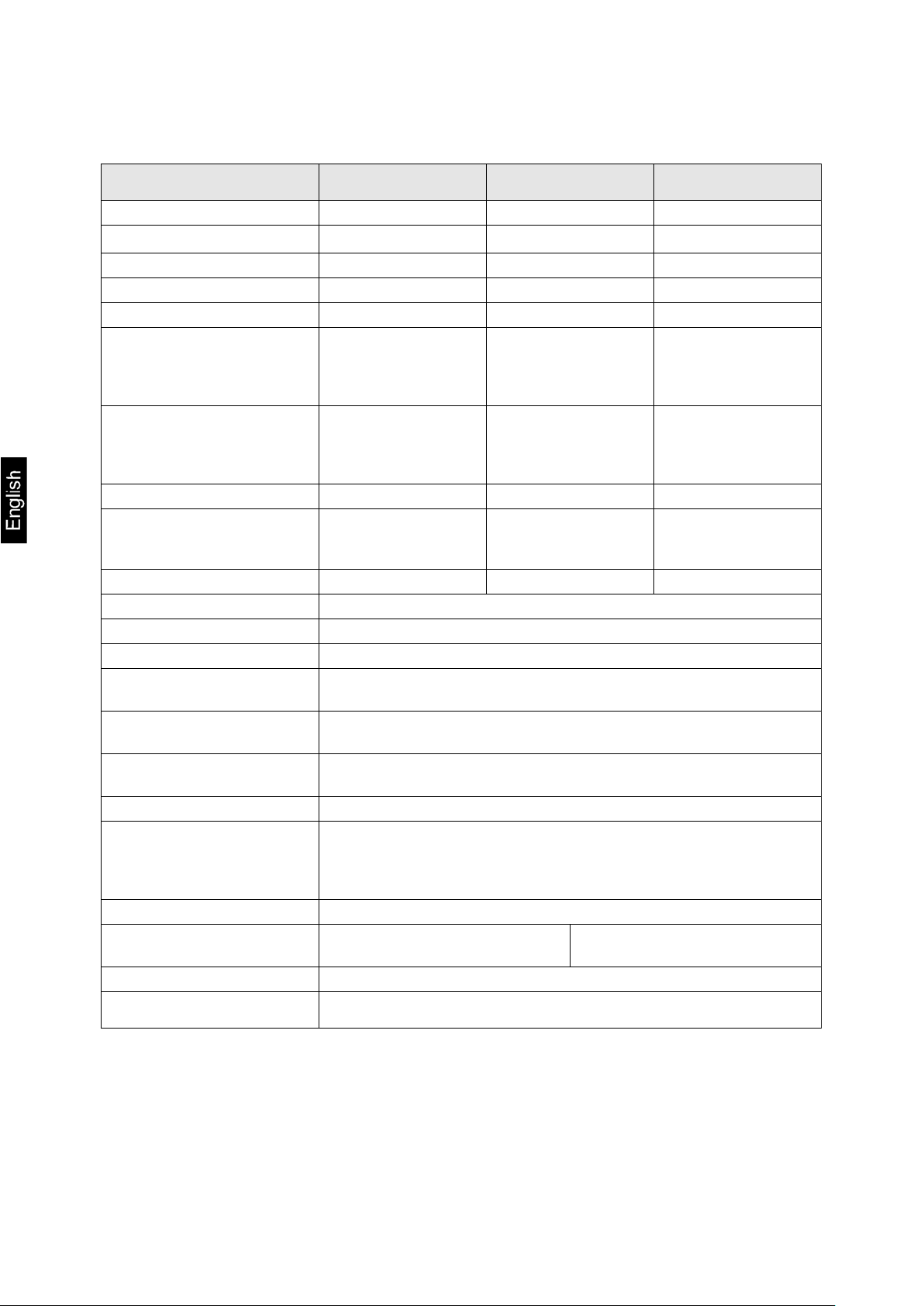
1 Technical specification
KERN CPE 6K-3 CPE 15K-3 CPE 30K-3
Product number / type TCPE 6K-3-A TCPE 15K-3-A TCPE 30K-3-A
Interval (d)
Linearity ±0,8 g ±3 g ±0,0015 kg
Minimum piece weight
when counting the number of
pieces in laboratory conditions*
0.2 g
100 mg 250 mg 500 mg
1 g 0.0005 kg
when counting the number of
pieces in standard condi-
Adjustment points 2/4/6 kg 5/10/15 kg 10/20/30 kg
Recommended
adjustment weight
(not delivered)
Heating time 120 min
Permissible
ambient temperature
Input voltage
Input voltage of
the power supply
Battery (optional) 3.7 V / 4 Ah
Rechargeable
battery operation
1 g 2.5 g 5 g
5 kg (F2) 10 kg (F2); 2 kg (F2) 20 kg (F2); 5 kg (F2)
0°C to +40°C
5 V, 1 A
100–240 VAC; 50/60 Hz
operating time 80 h (illumination off)
operating time 50 h (illumination on)
charging time ca. 5 h
housing dimensions [mm] 320 × 340 × 110 (width × depth × height)
Scale plate,
stainless steel [mm]
Net weight [kg] 2.9
Interface RS-232
* Minimum piece weight when counting the number of pieces in laboratory conditions:
There are optimum ambient conditions to count pieces with high resolution
No diversification of the counted pieces’ weight
**Minimum piece weight when counting the number of pieces in standard conditions:
There are unsteady ambient conditions (wind gusts, vibrations)
There is diversification of the counted pieces’ weight
TCPE_A-BA-e-2110 4
300 × 230 × 18 300 × 230 × 18
Page 5
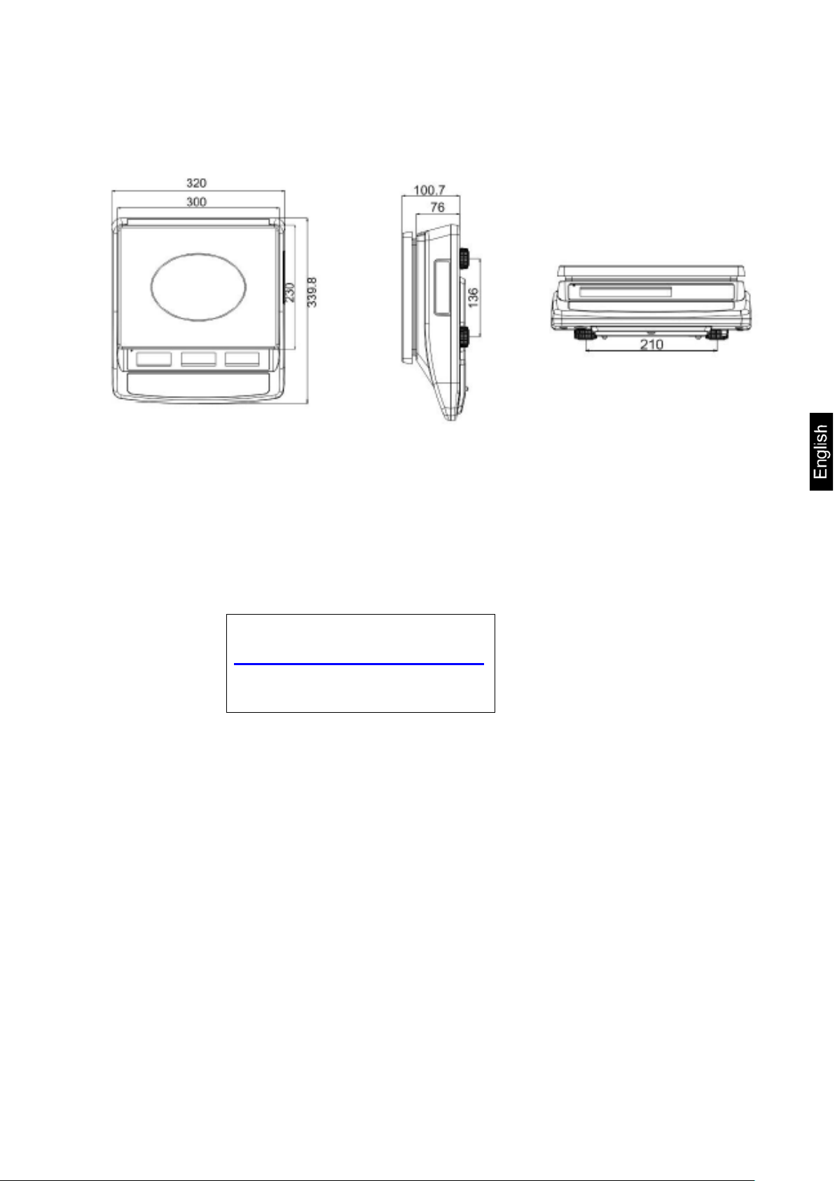
Dimensions:
2 Declaration of Conformity
The valid Declaration of Conformity EC/UE is available at:
www.kern-sohn.com/ce
5 TCPE_A-BA-e-2110
Page 6

3 Device overview
3.1 Parts
Item Name
1 Scale plate
2 Display
3 Keyboard
4 RS-232 interface
5 Battery charge indicator
6 Leveler
7 Leveling screw foot
8 Power supply socket
TCPE_A-BA-e-2110 6
Page 7
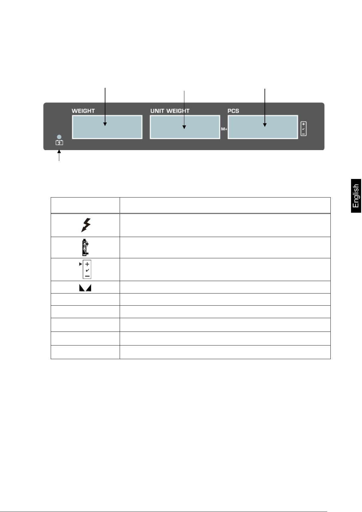
3.2 Display
Weight Weight of a single
piece
Battery charge indicator
Symbol Description
Battery charging indicator
Number of pieces
Discharged battery
Tolerance symbols for check weighing, see chapter 10.1
Stabilization indicator
ZERO Zero indicator
NET Net weight value indicator
g
kg
pcs
Weight unit “gram”
Weight unit “kilogram”
Unit of the application “Counting the number of pieces”
7 TCPE_A-BA-e-2110
Page 8
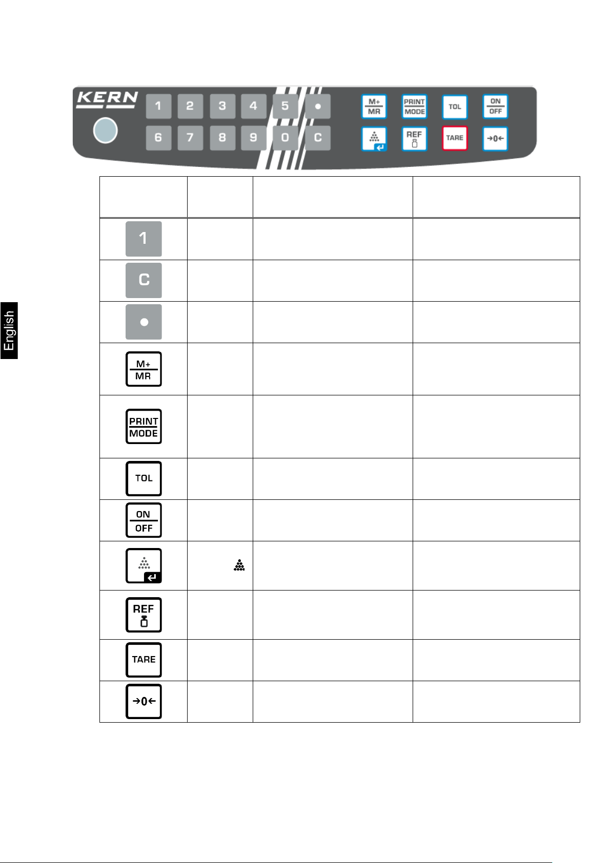
3.3 Keyboard
Button Name Function in the operating
mode
Numerical buttons –
Deleting –
Decimal point –
Summing
M Button
PRINT
button
Displaying the “total”
value
Weight data transfer via
the interface
Activating/deactivating
the test weighing mode
Menu function
–
Displaying the configuration menu
(by pressing and holding
the button)
–
ON/OFF
button
Button
REF button
TARE
button
ZERO
button
Switching on/off –
Determination of a single
piece average weight by
weighing
Introducing the known
weight of a single piece
in the numerical value
Taring Selecting the menu item
Zeroing Setting change
Selection confir mat ion / return to the weighing mode
–
TCPE_A-BA-e-2110 8
Page 9

4 Basic instructions (general information)
4.1 Intended use
The scale you bought is intended for weighing the weighed material. It should be considered a “non-automatic scale”, e.g. the weighed material should be carefully placed
manually on the scale plate center. The weight can be read after it has stabilized.
4.2 Non-intended use
The scale is not intended for dynamic weighing, e.g. for removing or adding small
amounts of the weighed material. The scale’s “stabilizing and compensating” mechanism can result i n display ing errone ous weighi ng results ! (Exampl e: slow out flow of t he
liquid from the container placed on the scale.)
Do not subject t he plat e to long-ter m load. T his may damage the weighing mechanism.
Avoid any scale impact and overload higher than the stipulated maximum load (Max),
deducting the tare from the existing load. This could damage the scale.
Never operate the scale in explosive atmospheres. The standard version is not explo-
sion-proof.
Never introduce a ny structural mo di fi cati o ns t o the scale. Thi s m ay result in dis play i ng
erroneous weighing results, violating the technical safety conditions, and also in scale
damage.
The scale should always be operated in line with the provided guidelines. Other operation ranges / areas require a written consent of KERN.
4.3 Guarantee
The warranty expires:
• if you fail to follow our guidelines included in the user manual;
• if you fail to use the device in line with the intended use;
• if you introduce any modifications or open the device;
• if the device gets damaged mechanically or damaged by the utilities, liqui ds and
ordinary wear and tear;
• if the device is not set correctly or the electrical system is not as required;
• if the weighing mechanism gets overloaded.
9 TCPE_A-BA-e-2110
Page 10

e parts of the original packaging in case you had to
Protect all the parts, e.g. wind breaker, scale plate, power supply etc.
4.4 Testing equipment supervision
Within the quali ty assurance sys tem, you mus t check the technical meas urement properties of the scale a nd possibly of t he availabl e referenc e weight re gularly. T o that aim,
the responsible user should define a relevant cycle, as well as the type and scope of
such an inspection. The information on the supervision of the testing equipment, i.e.
scales, and the required reference weights, can be found on the home page of KERN
(www.kern-sohn.com). The reference weights and scales can be calibrated fast and
for a low cost in the KERN calibration laboratory (against the national reference) approved by DKD (Deutsche Kalibrierdienst).
5 Basic safety instructions
5.1 Compliance with the instructions included in the user manual
Before you set and start the device, read this user manual thoroughly
even if you are familiar with KERN scales.
All language versions contain non-binding translation.
Only the original document in German is binding.
5.2 Personnel training
The device can be operated and maintained solely by trained workers.
6 Transport and storage
6.1 Checking during reception
Immediately after you have received the shipment, please check if it is free from any
visible outer damage. The same applies for the unpacked device.
6.2 Packaging / return transport
Please keep all th
send it back to us.
Always use the original packaging for the return transport.
Before you dispatch the device, disconnect any connected cables as
well as loose/moving parts.
Reinstall any transport locks, if present.
from slipping and damage.
TCPE_A-BA-e-2110 10
Page 11

7 Unpacking, positioning and s tart-up
7.1 Installation place, operation place
The scales are design ed to ensure r eliabl e weighi ng result s in standard operati ng c onditions.
The choice of a correct scale location ensures its accurate and fast operation.
This is why you should follow the following rules when selecting the installation place:
• Place the scale on stable, flat surface.
• Avoid extreme temperatures and temperature fluctuations, occurring e.g. when
you place it at the radiator or in a place exposed to direct sun rays.
• Protect the scale from the dir ect dra f t pres ent at open windows and doors.
• Avoid impact when weighing.
• Protect the scale from high hu midi ty of air, vapour s and dus t .
• Do not expose it to long-term heavy moisture. Any forbidden condensation of
the air moisture on the devic e may occur when a cold device is place d in a much
hotter environment. In such circumstances, leave the device not connected to
the mains for 2 hours to adapt to the ambient temperature.
• Avoid static discharge from the weighed material and scale container.
If there are any electromagnetic fields, static discharge and unstable power supply,
high readout deviations (erroneous weighing results) may occur. In such circumstances, change the location.
7.2 Unpacking and check
Remove the device and accessories from the packaging, remove the packaging material and place the device in the target location. Check if all components included in
the delivery are present and not damaged.
Scope of delivery / standard accessories:
• Scale, see chapter 3.1
• Power supply
• User manual
• Dust cover
11 TCPE_A-BA-e-2110
Page 12
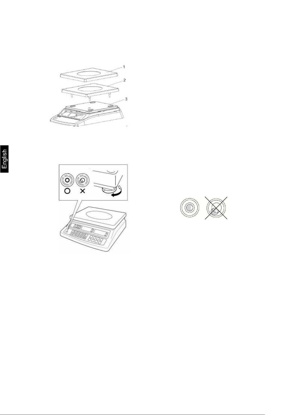
7.3 Integration, setting and leveling
Remove transport prot ect ion.
Install the scale plates as shown in the drawing.
Place the scale on smooth surface.
Level the scale using the leveling feet. The air bubble in the leveler must be pre-
sent in the marked area.
Check leveling at regular intervals.
TCPE_A-BA-e-2110 12
Page 13
Check if the scale voltage is set correctly. The scale can be connected to
Always use the origi nal power supply by K ERN. U sing any oth er produc ts
7.4 Power supply
the mains only when the voltage specified on the scale (sticker) and the
local voltage are identical.
requires KERN consent.
Important information:
Before you start the device, check the power cord for damage.
The power cord must not have any contact with liquids.
The plug must be always readily available.
13 TCPE_A-BA-e-2110
Page 14

Always replace the battery with the one of the same type or of
tions may result in its fire or explosion. It may result in serious
Do not connect the el ectri cal contacts of the b attery a nd do not
The electrolyte may be released by the damaged battery. Any
replace batteries, always pay attention to
When the power supply is connected, the battery operation
mode is switched off. Always remove the battery for weighing
colouration or deform ation, disconnect it immediately from the
7.5 Rechargeable battery operation
PLEASE
NOTE!
The rechargeable battery and the charger are compatible. Al-
ways use the power supply delivered with the scale.
Do not use the scale when charging.
the type recommended by the manufacturer.
The battery is not protected against all the environmental im-
pacts. Exposing the battery to specific environmental condiinjuries or material losses.
Protect the battery from fire and heat.
Do not allow the batt ery to have any c ontact with l iquids, chem-
icals or salts.
Do not expose the battery to high pressure or microwave radi-
ation.
Do not modify any batteries, charger and do not tamper them.
Do not use any faulty, damaged or deformed battery.
use any metal items to short circuit them.
contact of the elec trolyte with the ski n or eyes may irritate t hem.
When you place or
the correct polar ity ( se e the i nfor mation in the batter y co mpart ment).
in the power supply mode long er tha n 4 8 h! (Overheating danger).
If you detect any odour emitted by the battery, its heating, dis-
power supply and, whenever possible, from the scale.
TCPE_A-BA-e-2110 14
Page 15

7.5.1 Battery charging The rechargeable battery is charged using the supplied power cord.
Before first use, charge the battery for at least 5 hours using the power cord.
The battery symbol < > displayed on the screen means that the battery capacity will
soon run down. The device may operate ca. 1 hour longer and then it will be switched
off automatically. When the scale operates further without charging, a blinking <BERR> symbol will be displayed.
Charge the battery using the provided power supply.
When charging, LED i ndicator at the botto m, to the left of the wei ght indicator, i ndicates
the battery charging status.
red: The battery is being charged
green: The battery is fully charged
7.6 Connecting peripherals
Before you connect or disconnect any extra devices (printer, computer) to/from the
data interface, the scale should always be disconnected from the mains.
Use solely accessories and peripherals supplied by KERN with the scale, being perfectly compatible with it.
7.7 First start
To get accurate weighing results using electronic scales, ensure the scales achieves
the appropriate o perating temper ature (see “H eating time”, c hapter 1). Duri ng the heating time, the scale must be connected to the power source (the socket, rechargeable
battery or batteries).
The scale accuracy depends on the local standard gravity.
Always follow the guidelines in the “Adjustment” chapter.
15 TCPE_A-BA-e-2110
Page 16
Ensure stable environmental conditions. The heating time is required for the
• Ensure there are no obj ect s on the scal e pl at e .
7.8 Adjustment
As the standard gr avity value i s not the sa me in every s pot on Ear th, every di splay with
the scale plate connected should be adjusted, in line with the weighing rules resulting
from the laws of physics, to the standard gravity in the scale location (provided the
scale system has not already been subject to factory adjustment in its location). Such
an adjustment proces s should b e carri ed out during t he firs t start, fol lowi ng every location change and also in the case of any ambient temperature fluctuations. To ensure
achieving accurate measurement date, it is also recommended to carry out regular
display adjustment also in the weighing mode.
• Prepare the required adjustment weight, see chapter 1.
Whenever possible, adjust using the adjustment weight with the weight similar to the maximum load of the scale (the adjustment weight is recommended, see chapter 1). The adjustment may also be carried out using
weights with other nominal values or tolerance classes, but this is not optimal
from the measurement technique perspective. The adjustment weight precision must correspond to the interval [d] of the scale, though preferably it
should be a bit higher. For information concerning reference weights, see
online at: http://www.kern-sohn.com
•
stabilization (see chapter 1).
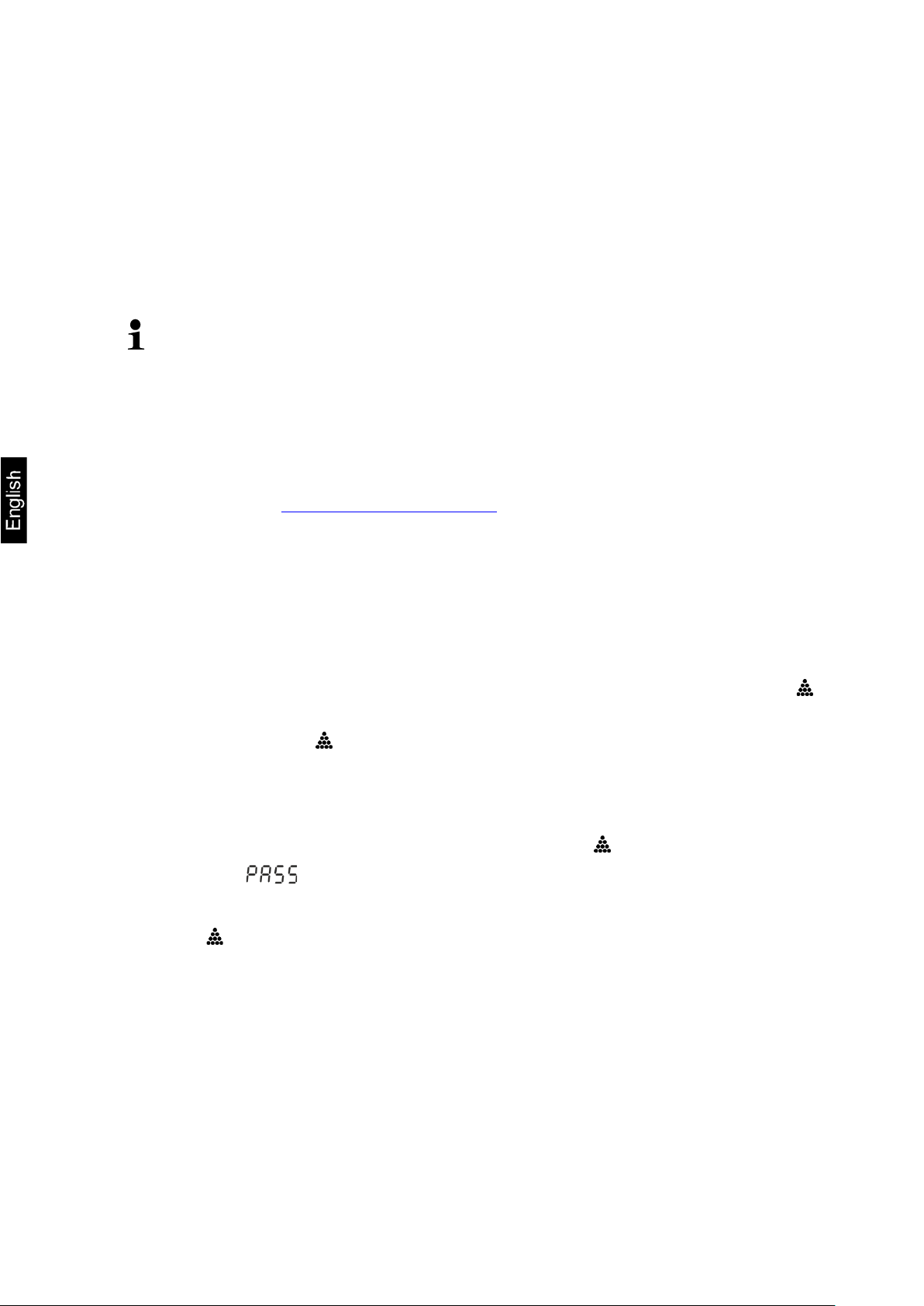
What to do:
Switch the scale on and when the autotest is carried out, press and hold the
button until the <ZERO ONE CAL> is displayed.
Release the button . <----- ONE CAL> and then the blinking symbol of the first
adjustment point will be displayed.
Using the ZERO button, select the required adjustment weight, see chapter 1
“Adjustment points” or “Recommended adjustment weight”.
Place the adjustment weight and confirm by press ing .
Wait until < > is displayed.
Remove the adjustment weight.
Press . After the successful adjustment, the scale will switch to the weighing
mode again automatically.
If there is any adjustment error or if an incorrect adjustment weight is used, the
error message is displayed. Repeat the adjustment process.
TCPE_A-BA-e-2110 16
Page 17
), deducting the tare from the existing load. This could damage
8 Operation
8.1 Switching on/off Switching on:
Press the ON/OFF button.
Once the displays is lit, the scale autotest will be carried out.
Wait until the weight is displayed, the scale is ready for use.
Switching off:
Press the ON/OFF button, the display will go off.
8.2 Zeroing
Zeroing corrects the effect of small pollutants on the scale plate.
Remove the load from the scale.
Press ZERO, the zero indications and <ZERO> symbol will be displayed.
8.3 Ordinary weighing
Check the zero indication, whenev er requi red zero by pres sing t he ZERO button.
Place the weighed material.
Wait until the stabilization indicator is displayed .
Read out the weighing result.
Overload warning
Always avoid any device overload higher than the stipulated maximum
load (Max
the device.
The exceeded maximum load is indicated with --ol--. Reduce the scale
load or reduce the initial load.
17 TCPE_A-BA-e-2110
Page 18
scale, the tare weight is displayed as a
To delete the saved tare value, remove the load from the scale plate and
pieces, the reference value must be sufficiently
than the placed reference load, the reference weight will be recalculated by
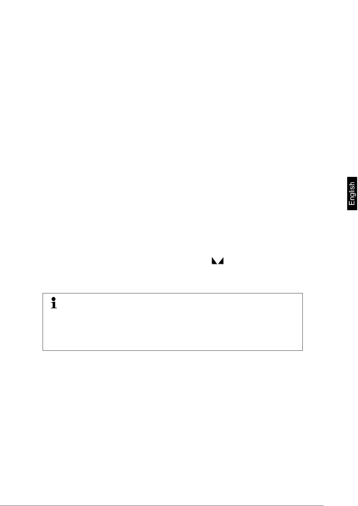
8.4 Weighing with tare
The empty weight of a ny container used for w eighing can b e tared, pr essing the butt on
which results in displaying the net weight of the weighed material during consecutive
weighing processes.
Place the scale container on the scale plate.
Wait until the stabilization indicator is displayed , and press TARE. The con-
tainer weight is saved in the scale memory. The zero indicator and the “NET”
symbol will be displayed.
“NET” indicates all displayed weight values are net values.
Place the weighed material.
Wait until the stabilization indicator is displayed .
Read out the net weight.
• After the load is removed from the
negative value.
•
press TARE button.
• The taring process can be repeat ed any number of times , e.g. when weighing several mixture i ngredients (making up the weight). The li mit is reached
when the complete taring scope is used.
9 Counting the number of pieces
Before it is possibl e to count piec es using th e scale, you s hould deter mine the aver age
weight of an indivi dual piece (unit w eight), the so-called reference v alue. To do i t, place
the specific number of pieces which the counting the number of pieces will be carried
out for. The scale will determine the total weight which will be divided by the number
of pieces, the so-called reference piece number. Next, based on the calculated mean
weight of an individual piece, the number of pieces will be counted.
• The higher number of the ref erence pi eces, the hig her the accuracy of counting the number of pieces.
• For small or highly diverse
high.
• For the minimum weight of the counted pieces, see the “Technical specification” table.
• The function is available starting from weight values above 20 d.
• Whenever required, when adding consecutive pieces with the number lower
the scale. Such a ref er ence v alue o pti misati on is indic ated by an a udibl e signal.
TCPE_A-BA-e-2110 18
Page 19

9.1 Determination of a single piece average weight by weighing
Zero the scale or, whenever required, tare the empty scale container.
Place the known number of individual pieces as a reference load.
Use numerical buttons to enter the number of reference pieces and confirm by
pressing . The “SAMP” symbol will be displayed for a while. The mean weight
of an individual piece will be determined by the scale and then the piece quantity will be displayed.
Remove the reference load. The scale is in the counting mode and counts all
pieces present on the scale plate.
Deleting the mean amount of a single piece:
Press .
19 TCPE_A-BA-e-2110
Page 20

9.2 Introducing the average weight of a single piece as the numerical value
Zero the scale or, whenever required, tare the empty scale container.
Using numerical buttons, enter the known average weight of a single piece, e.g.
10 g, and confirm by pressing REF.
The scale is in the counting mode and counts all pieces present on the scale
plate.
Deleting the mean amount of a single piece:
Press .
TCPE_A-BA-e-2110 20
Page 21

10 Test weighing
The function is available starting from weight values above 20 d.
Activating the test weighing mode:
In the weighing mode, press the TOL button, < CK OFF> will be displayed.
Pressing the TOL button enables to switch between <CK OFF> and
<CK ON >.
<CK OFF> function deactivated
<CK ON> function activated
10.1 Test weighing
The < Test weighing> appli cation enables to determine t he upper and l ower limit value
and, consequently, to ensure the weight of the weighed material belongs to the range
between the determined tolerance limits.
Exceeding the limit values (fall below and rise above) is signaled with a visual indication (tolerance symbols) and an audible indication.
Visual signal:
The triangle displayed at the right edge of the symbol provides the following information:
The weighed material above the preset limits
Weighed material in the preset limit range
The weighed material below the preset limits
Selection of the tes t weighing mode:
In the weighing mode, pres s a nd hold the TOL button f or 3 s, the <LIMIT – PCS-
TYPE> symbol will be displayed.
Pressing TOL enables to switch between
<LIMIT – PCS-TYPE> of the test counting mode and <<LIMIT – WEIGHT-
TYPE> of the test weighing mode.
Confirm the selection, pressing . A symbol used for introducing the sending
conditions <LIMIT – HI-MODE> will be displayed.
21 TCPE_A-BA-e-2110
Page 22

If the weighed porti on i s in the pr es ent li mit r ange, a sou nd is
If the weighed portion is below the lower limit value, the
If the weighed portion is above the upper limit value, the
If the weighed portion is in the preset limit range, the sound
If the weighed portion is below the lower limit value, the
he weighed portion is above the upper limit value, the
If the weighed portion is above the upper limit value, the
If the weighed portion is below the lower limit value, the
the weighed portion is below the lower limit value, the
If the weighed portion is above the lower limit value, the
Setting conditions of sending and limits:
1. When <LIMIT – HI-MODE> is displayed, use the TOL button to select the required sending condition.
You can choose:
In 1.
heard and a triangle is display ed at the [ ] symbol.
2.
sound is not heard and the triangle is displayed at the [–]
symbol.
3.
sound is not heard and the triangle is displayed at the [+]
symbol.
OUT 1.
is not heard an d t he triangle is displayed at t h e [+ ] s ymbol [
].
2.
sound is heard and th e triangle is displayed at the [–] symbol.
3. If t
sound is heard and the triangl e is displaye d at the [+] sy mbol.
HI 1.
sound is heard and the triangl e is displaye d at the [+] sy mbol.
2.
sound is not heard and the triangle is displayed at the [–]
symbol.
LO 1. If
sound is heard and th e triangle is displayed at the [–] symbol.
2.
sound is not heard and the triangle is displayed at the [+]
symbol.
2. Confirm the selection by pressing , <LIMIT – STABL-CHECK> will be dis-
played.
3. Select the required setting, pressing TOL.
LIMIT–STABLCHECK
LIMIT–UNSTACHECK
The sound can be heard solely for stable wei ghing values.
The sound can be h eard solely for stable and uns table
weighing values.
TCPE_A-BA-e-2110 22
Page 23

4. Confirm the selection by pressing . The window for value entr y in the num erical
form will be displayed where you can enter the upper limit value.
5. Using numerical buttons, enter the upper limit value, e.g. 2 kg in the displayed
unit (e.g. gram) and confirm by pressing .
6. The window for value entry in th e numeri cal fo rm wil l be di splaye d where yo u ca n
enter the lower limit value.
7. Using numerical buttons, enter the lower limit value, e.g. 1.5 kg in the displayed
unit (e.g. gram) and confirm by pressing . The scale will switch to the weighing
mode again.
23 TCPE_A-BA-e-2110
Page 24

Tolerance check start :
Ensure the test weighing mode is active. To do it, press TOL and, whenever re-
quired, use TOL to select <CK ON>.
Place the weighed m aterial (< 20 d) and, bas ed on the toler ance sy mbols / audibl e
signal, check if the weighed material belongs to the preset tolerance range.
Weighed material below the preset tolerance
Weighed material in the preset tolerance range
Weighed material above the preset tolerance
10.2 Check counting
The <Test counting> application enables to determine t he upper an d lower limit v alue
and, consequently, to ensure that the target number of pieces belongs to the range
between the determined tolerance limits.
Selection of the test counting mode:
In the weighing mode, press and hold the TOL button for 3 s, the current setting
will be displayed.
Pressing TOL enables to switch between
<LIMIT – PCS-TYPE> of the test counting mode and <<LIMIT – WEIGHT-
TYPE> of the test weighing mode.
Confirm the selection, pressing . A symbol used for introducing the signaling
conditions <LIMIT – HI-MODE> will be displayed.
TCPE_A-BA-e-2110 24
Page 25

The sound can be heard solely for stable weighing
The sound can be hear d solely for st able and unstabl e
Setting conditions of sending and limits:
Using the TOL button, select the required signaling condition. For selection op-
tions see chapter 10.1 / step 1:
Confirm the selection by pressing , <LIMIT – STABL-CHECK> will be dis-
played.
Select the required setting, pressing TOL.
LIMIT–STABL-
CHECK
LIMIT–UNSTA-
CHECK
Confirm the selection by pressing . The window for value entr y in the num erical
form will be displayed where you can enter the upper limit value.
values.
weighing values.
Using numerical buttons, enter the upper l imit val ue, e.g. 10 0 pieces, and confirm
by pressing .
The window for value entr y in th e numer ical f orm wil l be displaye d where y ou ca n
enter the lower limit value.
Using numerical buttons, enter the lower limit value, e.g. 90 pieces, and confirm
by pressing . The scale will switch to the weighing mode again.
25 TCPE_A-BA-e-2110
Page 26

Tolerance check start :
Ensure the test weighing mode is active. To do it, press TOL and, whenever re-
quired, use TOL to select <CK ON>.
Ensure the average weight of a single piece is set (see chapter 9).
Place the weighed m aterial (< 20 d) and, bas ed on the toler ance sy mbols / audibl e
signal, check if the weighed material belongs to the preset tolerance range.
Weighed material below the preset tolerance
Weighed material in the preset tolerance range
Weighed material above the preset tolerance
TCPE_A-BA-e-2110 26
Page 27

11 Summing
The function enables to add the number of pieces to the total memory by pressing the
button.
The function is available starting from weight values above 20 d.
Summing the weighed material:
Ensure the average weight of a single piece is determined (see chapter 9.
Whenever required, place an empty container on the scale and tare it.
Place the first weighed material. Wait until the stabilization indicator is displayed,
then press M. The number of pieces is added to the total memory. The number of
weighing procedures and the number of pieces are displayed for ca. 3 s intermittently with the currently placed weight.
Remove the weighed material. The subsequent weighed material can be added
only when the indication ≤ zero.
Place the second weighed material. Wait until the stabilization indicator is dis-
played, then press M. The number of pieces is added to the total memory. The
number of weighing procedures and the number of pieces are displayed for ca. 3
s intermittently with the currently placed weight.
Whenever required, add the subsequent weighed material as described above.
Load should be removed from the scale between consecutive weighing procedures.
This process may be repeated 99 times until you reach the scale weighing range.
Displaying the “total” value:
When zero is displayed, press M. The total number of pieces and the number of
weighing procedures will be displayed for ca. 3 s.
Deleting the total memory:
When zero is displayed, press the M button. When the total weight is displayed,
press C.
27 TCPE_A-BA-e-2110
Page 28

button for 3 s, the first menu item
BUAD96 USER SETUP
TARE
Menu leaving
speed
RS CO
rS oFF
Data transmission off
weighing values
values
rS Pr
Data transmission after PRINT is pressed
bl-AY
bl-AY
The backlight is switched on automatically when
load is changed or when the device is operated
bl-on
Display backlight always on
sponse time.
12 Setup menu
The setup menu enables to adapt the scale settings / scale behavior to your requirements (e.g. ambient conditions, special weighing processes).
Menu navigation:
Displaying the menu In the weighing mode , press and hold the PRINT
<
> will be displayed.
Selecting the menu item Individual menu items can be selected consec-
utively, pressing
.
Setting selection Confirm the selection of th e menu item by press-
ing the ZERO button. The firs t settin g will be di splayed.
Changing settings The ZERO enables to switc h betw ee n th e avail-
able settings.
Setting confirmation /
Press , the scale will switch to the weighing
mode again.
Overview:
Menu item Settings Description
BuAd96
Transmission
Data
BuAd96 Transmission speed 9600
BuAd48 Transmission speed 4800
rS Co
Continuous data trans mi ss i on of st able/unstable
transmission
rS SCo Continuous data transmission of stable weighing
rS St Data transmission for an unstable weighing value
Display backlight
bl-oFF Display backlight always off
FiLt-1
FiLt-1 ∼ FiLt-5
Filter
Adaptation to the ambient conditions, you can select from FiLt-1 ∼ FiLt-5 in the displayed unit (e.g.
gram)
The higher the filter degree, the faster the re-
TCPE_A-BA-e-2110 28
Page 29

SEnS-6
Sensitivity
Zero-0
Maintaining zero
L-AZ-0
Setting
a decimal point
SEnS-0∼
SEnS-9
Zero-0 ∼
Zero-9
L-AZ 0 ∼
L-AZ 9
Adaptation to the ambient conditions, you can select
from SEnS-0∼ SEnS-9.
The higher the degree, the higher the sensitivity.
Automatic zero maintenance, possible to choose from
0 d – 9 d
If the amount of the weighed material is reduced or increased significantly, the scale ’s “stabilizing and c ompensating” mechanism
can result in displaying erroneous weighing results! (e.g.: slow
outflow of the liquid from the container placed on the scale, evaporating processes).
When dosing with small weight fluctuations, it is recommended to
switch this function off.
The load scope where the scale returns to zero, you can
choose from 0 d – 9 d
13 RS-232 interface
RS-232 ensures two-way dat a exchange betw een the scale an d external dev ices. Data
is sent asynchronously in ASCII code.
To ensure communication between the balance and the printer, the following conditions must be met:
• Connect the scale wi th the printer interfac e using the appropr iate cable. Troublefree operation is ens ured only when t he appr opri ate int erfac e cabl e by KERN i s
used.
• Communication parameters (e.g. transmission speed) of the scale and the
printer must be compliant.
13.1 Technical specification
Port 9-Pin--pin mini D-Sub plug
Pin 2 RXD Input
Pin 3 TXD Output
Pin 5 GND Signal ground
Transmission
The choice of 4800/9600
speed
29 TCPE_A-BA-e-2110
Page 30

13.2 Printer mode / protocol templates (KERN YKB-01N)
Counting the
±1500,0g
Weight
number of
pieces
10g/pcs
150PCS
Weight of a single
piece
Number of pieces
Summing No possibility to connect with the
printer
13.3 Printout protocol (continuous data transmission)
Byte 1 2 3 4 5 6 7 8 9 10 11 12 13
+ <20> <20> 1 0 7 4 . 5 g <CR> <LF>
– <20> <20> <20> <20> 5 0 . 6 g <CR> <LF>
O L
Nr Description
1 The sign (plus/minus); alphabet: O
2 ∼ 8
9 ∼ 10
11 ∼ 12
7 bits of weighing value including the decimal point
Weight unit
End symbol
<20> Space
TCPE_A-BA-e-2110 30
Page 31

14 Mai ntenance, service and disposal
Before you start a ny works related to the maintenance, cl ea ni ng and repair, disconnect the device from the operating voltage.
14.1 Cleaning
Do not use any ag gr es s i ve c leaning agents ( sol vent s et c.) , but clean the device with a
cloth and mild soap s olution. T he liquid m ust not get i nside the devi ce. Wipe w ith a dry ,
soft cloth.
Any loose specimen/powder remains can be removed carefully with a brush or a
handheld vacuum cleaner.
Remove any scattered weighed material immediately.
14.2 Maintenance and service
The device can be operated and maintained solely by the technicians trained and
authorized by KERN.
Disconnect from the mains befor e op eni ng .
14.3 Disposal
The packaging and the device should be disposed in accordance with the national or
regional law in the location where the device is operated.
15 Error messages
Error message Explanation
--ol-- Overloading
B-ERR Discharged batteries/rechar g eable batteries
Err 9 Summing error
P-ERR Average weight of a single piece outside the range
31 TCPE_A-BA-e-2110
Page 32

16 Help for any minor f ail ures
If there are any program execution problems, the scale should be switched off and
disconnected from the mains f or a whil e. Next, t he weighi ng process should be start ed
anew.
Problem Possible cause
The weight indicator is not
lit.
The weight indication
keeps fluctuating.
The weighing result
is clearly wrong.
• The scale is not on.
• Interrupted mains connection (mains cable not
connected/damaged).
• Mains voltage failure.
• Draft / air movements.
• Table/air vibrations.
• The scale plate is in contact with foreign bodies.
• Electromagnetic fields / static discharge (select an-
other location / if possible, switch off the interfering
device).
• The scale indication was not reset.
• Incorrect adjustment.
• Scale not placed on a level surface.
• There are heavy temperature fluctuations.
• The heating time not observ ed.
• Electromagnetic fields / static discharge (select an-
other location / if possible, switch off the interfering
device).
TCPE_A-BA-e-2110 32
 Loading...