

Page 1

KERN & Sohn GmbH
Ziegelei 1
E-mail: info@kern-sohn.com
Phone: +49-[0]7433-9933-0
www.kern-sohn.com
Operating manual
Analytical and precision balances
KERN ALJ/ALS/PLJ/PLS
Type TALJG-A / TALSG-A / TPLJG-A / TPLSG-A
Version 1.2
2021-06
GB
D-72336 Balingen
Fax: +49-[0]7433-9933-149
TALJG_A/TALSG_A/TPLJG_A/TPLSG_A-BA-e-2112
Page 2

GB
KERN ALJ/ALS/PLJ/PLS
Analytical and precision balances
Version 1.2 2021-06
Operating manual
Contents
1 Technical specification ................................................................................. 5
2 Declaration of Conformity ........................................................................... 15
3 Device overview ........................................................................................... 16
3.1 Parts .........................................................................................................................16
3.2 Operating controls ....................................................................................................20
3.2.1 Keyboard overview ................................................................................................................... 20
3.2.2 Navigation buttons / Introducing the numerical value .............................................................. 21
3.3 Display overview .......................................................................................................22
3.4 User interface ...........................................................................................................23
4 Basic instructions ........................................................................................ 24
4.1 Intended use .............................................................................................................24
4.2 Non-intended use .....................................................................................................24
4.3 Warranty ...................................................................................................................24
4.4 Testing equipment supervision .................................................................................24
5 Basic safety instruct io n s ............................................................................ 25
5.1 Compliance with the instructions included in the user manual ...................................25
5.2 Personnel training .....................................................................................................25
6 Transport and storage ................................................................................. 25
6.1 Checking during reception ........................................................................................25
6.2 Packaging / return transport ......................................................................................25
7 Unpacking, positioning and start-up .......................................................... 28
7.1 Installation place, operation place .............................................................................28
7.2 Unpacking and check................................................................................................29
7.2.1 Setting....................................................................................................................................... 29
7.3 Power supply ............................................................................................................33
7.4 Operation with battery supply (solely the model PLS 420-3F) ...................................33
7.5 Operator language selection .....................................................................................34
7.6 Connecting peripherals .............................................................................................34
8 Adjustment ................................................................................................... 34
8.1 Adjustment mode selection .......................................................................................35
8.2 Automatic adjustment using the internal weight ........................................................36
8.3 Adjustment using the internal weight after the Model CAL button is pressed (models
ALJ/PLJ) ..............................................................................................................................37
8.4 Adjustment using the external weight ........................................................................38
8.5 Changing the weight of the internal calibration weight...............................................39
8.6 Adjustment report display/print ..................................................................................40
8.7 Verification ................................................................................................................41
9 Basic mode ................................................................................................... 42
2 TALJG_A/TALSG_A/TPLJG_A/TPLSG_A-BA-e-2112
Page 3

9.1 Switching the scale on and off ..................................................................................42
9.2 Resetting ..................................................................................................................42
9.3 Ordinary weighing .....................................................................................................43
9.4 Weighing range indicator ..........................................................................................43
9.5 Taring .......................................................................................................................44
9.6 Weighing using the under-scales weighing hanger ...................................................45
11 Setup menu .................................................................................................. 46
11.1 Weight units (unit1/unit2) ..........................................................................................49
11.2 RS-232 .....................................................................................................................50
11.3 Transmission speed ..................................................................................................51
11.4 Aut o zero ..................................................................................................................52
11.5 Filter .........................................................................................................................53
11.6 Stability .....................................................................................................................53
11.7 Set ting the display contrast .......................................................................................54
11.8 Dis p lay backlight .......................................................................................................55
11.9 Autom atic switch-off function ....................................................................................55
11.10 Setting time and date ............................................................................................56
11.11 User interface language ........................................................................................57
12 Main menu “Applications” .......................................................................... 58
12.1
12.1.1 Determining the reference value by weighin g ...................................................................... 59
12.1.2 Introducing the reference weight in the numerical value ..................................................... 62
12.1.3 Automatic optimization of the reference value ..................................................................... 63
12.2 Det er mining density using the equipment for the under-scales weighing hanger ......64
12.2.1 Determining solid body density using the equipment for the under-scales weighing hanger
64
12.2.2 Liquid density determination ................................................................................................ 68
12.3 Formulation ...............................................................................................................70
12.3.1 Free formulation ................................................................................................................... 70
12.3.1 Formulation defining and implementat ion ............................................................................ 72
12.4 Test weighing ...........................................................................................................81
12.5 Det er mining the percentage value ............................................................................84
12.5.1 Entering the reference weight by weighing .......................................................................... 84
12.5.2 Introducing the reference weight in the numerical value ..................................................... 85
12.6 Weighing animals .....................................................................................................86
12.7 Peak value function ..................................................................................................87
12.8 GLP function (Good Laboratory Practice) .................................................................88
Counting the number of pieces .................................................................................59
13 RS-232C interface ........................................................................................ 90
13.1 Technical specification ..............................................................................................90
13.2 Use of t he scale plug pins .........................................................................................90
13.3 Interface....................................................................................................................
13.3.1 Printer connection ................................................................................................................ 92
91
13.4 Dat a transmission .....................................................................................................92
13.5 Data transmission formats ........................................................................................92
13.6 Rem ot e control command .........................................................................................94
14 Error messages ............................................................................................ 95
15 Maintenance, service and disposal ............................................................ 95
15.1 Cleaning ...................................................................................................................95
15.2 Maintenanc e and service ..........................................................................................95
TALJG_A/TALSG_A/TPLJG_A/TPLSG_A-BA-e-2112 3
Page 4

15.3 Disposal ....................................................................................................................96
16 Help for any minor failures ......................................................................... 96
17 Ionizing unit (factory option for KERN ALJ-A03) ...................................... 97
17.1 General information ..................................................................................................97
17.2 Basic s af ety instructions ...........................................................................................97
17.3 Technical specification ..............................................................................................99
17.4 Device overview ........................................................................................................99
17.5 Start ........................................................................................................................ 100
17.6 Intended use ........................................................................................................... 101
17.7 Cleaning ................................................................................................................. 101
4 TALJG_A/TALSG_A/TPLJG_A/TPLSG_A-BA-e-2112
Page 5

1 Technical specification
counting the number of pieces in
counting the number of pieces in
KERN ALJ 160-4A ALJ 210-5A ALJ 200-5DA
Product number / type TALJG 160-4-A
Weighing range (Max) 160 g
Interval (d) 0.1 mg
Reproducibility 0.1 mg
Linearity ±0.3 mg
Settling time (standard) 4 s
Minimum part weight when
1 mg
laboratory conditions*
Minimum part weight when
10 mg
standard conditions**
Heating time 8 h
Adjustment weight internal
Number of reference pieces
when counting the number of
pieces
10, 25, 50, 100, selected freely
TALJG 210-5-A
210 g
0.01 mg
0.05 mg
± 0.1 mg
6 sec.
1 mg
10 mg
TALJG 220-5-A
82 g/220 g
0.01 mg/0.1 mg
0.04 mg/0.1 mg
±0.1 mg/0.2 mg
10 s
1 mg
10 mg
Weight units
Power supply
Operating temperature +15°C ... +30°C
Air humidity max. 80% (non-condensing)
Housing (W × D × H) mm 210 × 340 × 330
Wind breaker dimensions
(W × D × H) mm
Scale plate (stainless steel) Ø 80 mm
(Net) weight kg 6.5 kg 7 kg
Interface RS-232C
Contamination degree 2
Overvoltage category Category II
Installation height
above sea level
tl (Hong Kong), tl (Singapore, Malaysia), tl (Taiwan), pen
160 × 140 × 205
(inner)
190 × 195 × 225
(outer)
ct, g, gn, lb, mo, oz, ozt,
24 V DC, 1A
160 x 170 x 225
(inner)
172 x 185 x 245
(outer)
up to 4000 m
160 × 170 × 225
190 × 195 × 225
(inner)
(outer)
Location site Solely indoors
TALJG_A/TALSG_A/TPLJG_A/TPLSG_A-BA-e-2112 5
Page 6

KERN ALJ 250-4A ALJ 310-4A ALJ 500-4A
counting the number of pieces in
counting the number of pieces in
Product number / type TALJG 250-4-A TALJG 310-4-A TALJG 510-4-A
Weighing range (Max) 250 g 310 g 510 g
Interval (d) 0.1 mg 0.1 mg 0.1 mg
Reproducibility 0.1 mg 0.1 mg 0.2 mg
Linearity ±0.3 mg ±0,3 mg ±0,4 mg
Settling time (standard) 4 s 4 s 4 s
Minimum part weight when
1 mg 1 mg 1 mg
laboratory conditions*
Minimum part weight when
10 mg 10 mg 10 mg
standard conditions**
Heating time 8 h
Adjustment weight internal
Number of reference pieces
when counting the number of
pieces
10, 25, 50, 100, selected freely
Weight units
Power supply
Operating temperature +5°C ... +30°C
Air humidity max. 80% (non-condensing)
Housing (W × D × H) mm 210 × 340 × 330
Wind breaker dimensions
(W × D × H) mm
Scale plate (stainless steel) Ø 80 mm
(Net) weight kg 6.5 kg
Interface RS-232C
Contamination degree 2
Overvoltage category Category II
Installation height
above sea level
tl (Hong Kong), tl (Singapore, Malaysia), tl (Taiwan), pen
ct, g, gn, lb, mo, oz, ozt,
24 V DC, 1A
160 × 140 × 205 (inner)
190 × 195 × 225 (outer)
up to 4000 m
Location site Solely indoors
6 TALJG_A/TALSG_A/TPLJG_A/TPLSG_A-BA-e-2112
Page 7

KERN ALJ 160-4AM ALJ 250-4AM
Product number / type TALJG 160-4M-A TALJG 250-4M-A
Weighing range (Max) 160 g 250 g
Interval (d) 0.1 mg 0.1 mg
Reproducibility 0.1 mg 0.1 mg
Linearity ±0.3 mg ±0,3 mg
Verification scale interval (e) 1 mg 1 mg
Verification class I I
Minimum weight (Min) 10 mg 10 mg
Settling time (standard) 4 s 4 s
Minimum part weight when counting
the number of pieces in laboratory
conditions*
Minimum part weight when counting
the number of pieces in standard
conditions**
1 mg 1 mg
10 mg 10 mg
Heating time 8 h
Adjustment weight internal
Number of reference pieces
when counting the number of pieces
Weight units ct, g
Power supply
Operating temperature +15°C ... +30°C
Air humidity max. 80% (non-condensing)
Housing (W × D × H) mm 210 × 340 × 330
Wind breaker dimensions
(W × D × H) mm
Scale plate (stainless steel) Ø 80 mm
(Net) weight kg 6,5
Interface RS-232C
Contamination degree 2
10, 25, 50, 100, selected freely
24 V DC, 1A
160 × 140 × 205 (inner)
190 × 195 × 225 (outer)
Overvoltage category Category II
Installation height
above sea level
Location site Solely indoors
up to 4000 m
TALJG_A/TALSG_A/TPLJG_A/TPLSG_A-BA-e-2112 7
Page 8

KERN ALS 160-4A ALS 250-4A
Product number / type TALSG 160-4-A TALSG 250-4-A
Weighing range (Max) 160 g 250 g
Interval (d) 0.1 mg 0.1 mg
Reproducibility 0.1 mg 0.1 mg
Linearity ±0.3 mg ±0,3 mg
Settling time (standard) 4 s 4 s
Minimum part weight when counting
the number of pieces in laboratory
conditions**
Minimum part weight when counting
the number of pieces in standard
conditions**
Heating time 8 h
Recommended adjustment weight
(class),
not delivered
1 mg 1 mg
10 mg 10 mg
150 g (E2) 250 g (E2)
Number of reference pieces
when counting the number of pieces
Weight units
Power supply
Operating temperature +15°C ... +30°C
Air humidity max. 80% (non-condensing)
Housing (W × D × H) mm 210 × 340 × 330
Wind breaker dimensions
(W × D × H) mm
Scale plate (stainless steel) Ø 80 mm
(Net) weight kg 6,2 kg
Interface RS-232C
Contamination degree 2
Overvoltage category Category II
10, 25, 50, 100, selected freely
ct, g, gn, lb, mo, oz, ozt,
tl (Hong Kong), tl (Singapore, Malaysia), tl
(Taiwan), pen
24 V DC, 1A
160 × 140 × 205 (inner)
190 × 195 × 225 (outer)
Installation height
above sea level
Location site Solely indoors
up to 4000 m
8 TALJG_A/TALSG_A/TPLJG_A/TPLSG_A-BA-e-2112
Page 9

KERN PLJ 420-3F PLJ 720-3A PLJ 1200-3A
counting the number of pieces in
counting the number of pieces in
Product number / type TPLJG 420-3-A TPLJG 720-3-A TPLJG 1200-3-A
Weighing range (Max) 420 g 720 g 1200 g
Interval (d) 0.001 g 0.001 g 0.001 g
Reproducibility 0.001 g 0.001 g 0.001 g
Linearity ±0.003 g ±0,002 g ±0,003 g
Settling time (standard) 2 s 2 s 2 s
Minimum part weight when
5 mg 1 mg 5 mg
laboratory conditions**
Minimum part weight when
50 mg 10 mg 50 mg
standard conditions**
Heating time 4 h 4 h 8 h
Adjustment weight internal
Number of reference pieces
when counting the number of
pieces
10, 25, 50, 100, selected freely
Weight units
Power supply
Operating temperature +15°C/+30°C
Air humidity max. 80% (non-condensing)
Equipment for the under-scales
weighing hanger
Housing (W × D × H) mm 210 × 340 × 160
Wind breaker [mm]
Scale plate (stainless steel) Ø 11 cm
(Net) weight kg
Interface RS-232C
Contamination degree 2
Overvoltage category Category II
tl (Hong Kong), tl (Singapore, Malaysia), tl (Taiwan), pen
230 V/50 Hz
(Euro) 9 VDC
– attachment lug, serial equipment
3.5 kg 4.9 kg 4.9 kg
ct, g, gn, lb, mo, oz, ozt,
230 V/50 Hz (Euro) 24 V DC
internal: Ø 150, height 60
external: Ø 160, height 70
Installation height
above sea level
Location site Solely indoors
TALJG_A/TALSG_A/TPLJG_A/TPLSG_A-BA-e-2112 9
up to 4000 m
Page 10

KERN PLJ 2000-3A PLJ 4200-2F PLJ 6200-2A
number of pieces in
counting the number of pieces in
Product number / type TPLJG 2100-3-A TPLJG 4200-2-A TPLJG 6200-2-A
Weighing range (Max) 2100 g 4200 g 6200 g
Interval (d) 0.001 g 0.01 g 0.01 g
Reproducibility 0.002 g 0.02 g 0.01 g
Linearity ±0.004 g ±0,04 g ±0,03 g
Settling time (standard) 2 s 2 s 2 s
Minimum part weight when
counting the
laboratory conditions**
Minimum part weight when
standard conditions**
Heating time 8 h 4 h 4 h
Adjustment weight internal
Number of reference pieces
when counting the number of
pieces
50 mg 50 mg 10 mg
500 mg 500 mg 100 mg
10, 25, 50, 100, selected freely
Weight units
Power supply
Operating temperature +15°C ... +30°C
Air humidity max. 80% (non-condensing)
Equipment for the under-scales
weighing hanger
Housing (W × D × H) mm
Wind breaker mm
internal: Ø 150, height 60
external: Ø 160, height 70
Scale plate (stainless steel) Ø 11 cm Ø 16 cm Ø 16 cm
(Net) weight kg
Interface RS-232C
Contamination degree 2
Overvoltage category Category II
tl (Hong Kong), tl (Singapore, Malaysia), tl (Taiwan), pen
230 V/50 Hz
(Euro) 24 V DC
attachment lug,
serial
equipment
210 x 340 x 330 210 x 340 x 95 210 x 340 x 160
yes no no
6.8 kg 3.8 kg 5.4 kg
ct, g, gn, lb, mo, oz, ozt,
230 V/50 Hz
(Euro) 9 VDC
–
230 V/50 Hz
(Euro) 24 V DC
attachment lug,
serial
equipment
Installation height
above sea level
Location site Solely indoors
10 TALJG_A/TALSG_A/TPLJG_A/TPLSG_A-BA-e-2112
up to 4000 m
Page 11

KERN PLJ 720-3AM PLJ 6200-2AM
counting the number of pieces in
Product number / type TPLJG 720-3M-A TPLJG 6200-2M-A
Weighing range (Max) 720 g 6200 g
Interval (d) 0.001 g 0.01 g
Reproducibility 0.001 g 0.01 g
Linearity ±0.002 g ±0,02 g
Verification scale interval (e) 10 mg 100 mg
Verification class II II
Minimum weight (Min) 20 mg 50 mg
Settling time (standard) 2 s 2 s
Minimum part weight when
counting the number of pieces in
laboratory conditions**
Minimum part weight when
standard conditions**
Heating time 4 h 4 h
1 mg 10 mg
10 mg 100 mg
Adjustment weight internal
Number of reference pieces
when counting the number of
pieces
Weight units ct, g
Power supply
Operating temperature +15°C ... +30°C
Air humidity max. 80% (non-condensing)
Housing (W × D × H) mm
Wind breaker [mm]
Scale plate (stainless steel) Ø 11 cm Ø 16 cm
(Net) weight kg
Interface RS-232C
Contamination degree 2
Overvoltage category Category II
210 x 345 x 155 210 x 345 x 160
10, 25, 50, 100, selected freely
230V/50Hz AC (Euro), 24V/1A DC
internal: Ø 150, height 60
external: Ø 160, height 70
4.9 kg 5.4 kg
Installation height
above sea level
Location site Solely indoors
TALJG_A/TALSG_A/TPLJG_A/TPLSG_A-BA-e-2112 11
up to 4000 m
Page 12

KERN
PLS 420-3F
PLS 720-3A
PLS 1200-3A
Product number / type TPLSG 420-3-A TPLSG 720-3-A TPLSG 1200-3-A
Linearity
±0.004 g
±0,002 g
±0,003 g
Settling time (standard)
3 s
2 s
2 s
Operating temperature
+15°C ... +30°C
Air humidity
max. 80% (non-condensing)
Housing (W × D × H) mm
210 × 340 × 160
Interface
RS-232C
Contamination degree
2
above sea level
Weighing range (Max) 420 g 720 g 1200 g
Interval (d) 0.001 g 0.001 g 0.001 g
Reproducibility 0.001 g 0.001 g 0.001 g
Minimum part weight when
counting the number of
pieces in laboratory
conditions**
Minimum part weight when
counting the number of
pieces in standard
conditions**
Heating time 4 h 4 h 8 h
Recommended adjustment
weight (class),
not delivered
Number of reference pieces
when counting the number of
pieces
5 mg 5 mg 5 mg
50 mg 50 mg 50 mg
400 g (E2) 600 g (E2) 1 kg (E2)
10, 25, 50, 100, selected freely
Weight units
Power supply
Battery
Equipment for the underscales weighing hanger
Wind breaker mm
Scale plate (stainless steel) Ø 11 cm
(Net) weight kg 2,7 kg 4.5 kg 4.5 kg
Overvoltage category Category II
tl (Hong Kong), tl (Singapore, Malaysia), tl (Taiwan), pen
230 V/50 Hz (
Euro) 9 VDC
operating time 30 h
charging time 10 h
ct, g, gn, lb, mo, oz, ozt,
230 V/50 Hz (Euro) 24 V DC
– –
attachment lug, serial equipment
internal: Ø 150, height 60
external: Ø 160, height 70
Installation height
Location site Solely indoors
12 TALJG_A/TALSG_A/TPLJG_A/TPLSG_A-BA-e-2112
up to 4000 m
Page 13

KERN PLS 4200-2F PLS 6200-2A
the number of pieces in
counting the number of pieces in
Product number / type TPLSG 4200-2-A TPLSG 6200-2-A
Weighing range (Max) 4200 g 6200 g
Interval (d) 0.01 g 0.01 g
Reproducibility 0.01 g 0.01 g
Linearity ±0.04 g ±0,03 g
Settling time (standard) 3 s 2 s
Minimum part weight when
counting
laboratory conditions**
Minimum part weight when
standard conditions**
Heating time 4 h 4 h
Recommended adjustment
weight (class),
not delivered
Number of reference pieces
when counting the number of
pieces
50 mg 50 mg
500 mg 500 mg
4 kg (E2) 5 kg (E2)
10, 25, 50, 100, selected freely
Weight units
Power supply
Battery
Operating temperature +15°C ... +30°C
Air humidity max. 80% (non-condensing)
Equipment for the under-scales
weighing hanger
Housing (W × D × H) mm
Wind breaker no
Scale plate (stainless steel) Ø 16 cm
(Net) weight kg 3 kg 4.5 kg
Interface RS-232C
Contamination degree 2
Overvoltage category Category II
tl (Hong Kong), tl (Singapore, Malaysia), tl (Taiwan), pen
230 V/50 Hz (Euro)
operating time 30 h
charging time 10 h
ct, g, gn, lb, mo, oz, ozt,
230 V/50 Hz (Euro)
9 V DC
attachment lug, serial equipment
24 V DC
210 x 345 x 105
–
Installation height
above sea level
Location site Solely indoors
TALJG_A/TALSG_A/TPLJG_A/TPLSG_A-BA-e-2112 13
up to 4000 m
Page 14

KERN PLS 8000-2A
counting the number of pieces in
counting the number of pieces in
PLS 20000-1F
Product number / type TPLSG 8200-2-A TPLSG 20000-1-A
Weighing range (Max) 8200 g 20 kg
Interval (d) 0.01 g 0.1 g
Reproducibility 0.01 g 0.1 g
Linearity ±0.04 g ±0,4 g
Settling time (standard) 4 s 3 s
Minimum part weight when
10 mg 500 mg
laboratory conditions*
Minimum part weight when
100 mg 5 g
standard conditions**
Heating time 4 h 4 h
Recommended adjustment
weight (class), not delivered
5 kg (E2) 20 kg (E2)
Number of reference pieces
when counting the number of
10, 25, 50, 100, selected freely
pieces
Weight units
tl (Hong Kong), tl (Singapore, Malaysia), tl (Taiwan), pen
Power supply 230 V/50 Hz (Euro)
24 V DC
ct, g, gn, lb, mo, oz, ozt,
230 V/50 Hz (Euro)
9 V DC
Operating temperature +15°C ... +30°C
Air humidity max. 80% (non-condensing)
Equipment for the under-scales
weighing hanger
attachment lug, serial
equipment
-
Housing (W × D × H) mm 210 × 345 × 100 210 × 340 × 100
Wind breaker no no
Scale plate (stainless steel) Ø 16 cm 200 x 175 mm
(Net) weight kg
4.8 kg 3.5 kg
Interface RS-232C
Contamination degree 2
Overvoltage category Category II
Installation height
above sea level
Location site Solely indoors
14 TALJG_A/TALSG_A/TPLJG_A/TPLSG_A-BA-e-2112
up to 4000 m
Page 15

* Minimum part weight when counting the number of pieces in laboratory
For verified scales (= the ones subject to the conformity
assessment procedure), the Declaration of Conformity is included
conditions:
There are optimum ambient conditions to count pieces with high resolution
No diversification of the counted pieces’ weight
**Minimum part weight when counting the number of pieces in standard
conditions:
There are unsteady ambient conditions (wind gusts, vibrations)
There is diversification of the counted pieces’ w eig ht
2 Declaration of Conformity
The valid Declaration of Conformity EC/UE is available at:
www.kern-sohn.com/ce
in the delivery scope.
TALJG_A/TALSG_A/TPLJG_A/TPLSG_A-BA-e-2112 15
Page 16

3 Device overview
3.1 Parts
Front:
Model ALJ 200-5DA Models ALJ/ALS
Modell TALJG 210-5-A
Item Name
1 Glass wind breaker
2 Wind breaker ring
3 Scale plate
4 Leveler
5 Display
6 Keyboard
7 Leveling screw foot
8 Ionisator
16 TALJG_A/TALSG_A/TPLJG_A/TPLSG_A-BA-e-2112
Page 17

Model PLJ 2000-3A
Models PLJ/PLS:
Scale plate dimensions Ø 110 mm
Item Name Item Name
1 Glass wind breaker 1 Leveler
2 Scale plate 2 Cover of the glass wind breaker
3 Display 3 Glass wind breaker
4 Keyboard 4 Scale plate
5 Leveling screw foot 5 Display
6 Leveler 6 Leveling screw foot
7 Keyboard
TALJG_A/TALSG_A/TPLJG_A/TPLSG_A-BA-e-2112 17
Page 18

Models PLS
scale plate dimensions Ø 160 mm
Item Name
1 Leveler
Models PLS 20000-1F
scale plate dimensions 200 x 175 mm
2 Scale plate
3 Display
4 Keyboard
5 Leveling screw foot
Sample drawing with a ionizing unit installed (KERN ALJ-A03):
18 TALJG_A/TALSG_A/TPLJG_A/TPLSG_A-BA-e-2112
Page 19

Scale back and bottom
2
3
4
5
6
5
7
1. Scale plate
2. RS-232C interface
3. Leveling screw foot
4. Power supply socket
5. Housing screws
(in models with 4
leveling screw feet,
first screw out both rear
ones)
6. Equipment for the
under-scales weighing
hanger
7. Transport protecti on
(solely models with an
internal adjustment
weight)
TALJG_A/TALSG_A/TPLJG_A/TPLSG_A-BA-e-2112 19
Page 20

3.2 Operating controls
Button
Name
Button pressing
Pressing and holding
sound is heard
3.2.1 Keyboard overview
the button until the
MENU
button
CAL button
ON/OFF
button
PRINT
button
TARE
button
• Displaying the main /
• Menu item selection —
• Switching on/off
• Leaving the main / application menu,
• Adjustment
• Menu item selection — scrolling backward
• Weight data transfer via the interface
• Setting confirmatio n/saving
• Taring
• Resetting
application menu
scrolling forward
return to the weighing mode
• Displaying the setup
menu
• Leaving the setup
menu
20 TALJG_A/TALSG_A/TPLJG_A/TPLSG_A-BA-e-2112
Page 21

3.2.2 Navigation buttons / Introducing the numerical value
Button Name Button pressing Pressing and holding
the button
Navigation
button
Navigation
button
Navigation
button
Navigation
button
ESC
• Increasing the digit value
• In the menu: scrolling
forward
• Decreasing the digit value
• In the menu: scrolling
backward
• Digit positioning
• Entry deleting
Saving
Canceling
Setting a decimal point
Changing to
upper/lowercase
TALJG_A/TALSG_A/TPLJG_A/TPLSG_A-BA-e-2112 21
Page 22

3.3 Display overview
Item
Name
2
4
Weighing value
7
1
Weighing range indicator
Stabilization indicator
3
5
6
Zero indicator
Unit
Current time
Current date
Symbol Description see chapter
Stabilization indicator
PC
H
Zero indicator
The scale is in the percentage value determination mode
The scale is in the piece count mode
Upper limit value
+ chapter 9.3
+ chapter 9.3
+ chapter 12.5
+ chapter 12.1
+ chapter 12.4
L
Lower limit value
ct, g, gn, lb, mo,
tl (Hong Kong),
22 TALJG_A/TALSG_A/TPLJG_A/TPLSG_A-BA-e-2112
DS
oz, ozt,
tl (Singapore,
Malaysia), tl
(Taiwan), pen
The scale is in the density determination mode
The scale is in the data entry mode
Weight units
In the verified scales, the non-verified value is displayed in brackets
+ chapter 12.2
+ chapter 11.1
Page 23

3.4 User interface
Item
Name
8
Operation carried out
Once the application is downloaded, the operator is guided step by step. It is possible
to select a language (D, GB, F, IT, ESP, P; see chapter 11.11).
Display example “Piece count”
9
10
11
Active application
Current date
Current time
TALJG_A/TALSG_A/TPLJG_A/TPLSG_A-BA-e-2112 23
Page 24

4 Basic instructions
4.1 Intended use
The scale you bought is intended for weighing the weighed material. It should be
considered a “non-automatic scale”, e.g. the weighed material should be carefully
placed manually on the scale plate center. The weight can be read after it has
stabilized.
4.2 Non-intended use
Do not use the scale for dynamic weighing. If the amount of the weighed material is
reduced or increased significantly, the scale’s “stabilizing and compensating”
mechanism can result in displaying erroneous weighing results! (Example: slow
outflow of the liquid from the container placed on the scale.)
Do not subject the plate to long-term load. This may damage the weighing
mechanism.
Avoid any scale impact and overload higher than the stipulated maximum load (Max),
deducting the tare from the existing load. This could damage the scale.
Never operate the scale in explosive atmospheres. The standard version is not
explosion-proof.
Never introduce any structural modifications to the scale. This may result in
displaying erroneous weighing results, violating the technical safety conditions, and
also in scale damage.
The scale should always be operated in line with the provided guidelines. Other
operation ranges / areas require a written consent of KERN .
4.3 Warranty
The warranty expires:
• if you fail to follow our guidelines included in the user manual;
• if you fail to use the device in line with the intended use;
• if you introduce any modifications or open the device;
• if the device gets damaged mechanically or damaged by the utilities, liquids and
ordinary wear and tear;
• if the device is not set correctly or the electrical system is not as required;
• if the weighing mechanism gets overloaded.
4.4 Testing equipment super vi s ion
Within the quality assurance system, you must check the technical measurement
properties of the scale and possibly of the available reference weight regularly. To
that aim, the responsible user should define a relevant cycle, as well as the type and
scope of such an inspection. The information on the supervision of the testing
equipment, i.e. scales, and the required reference weights, can be found on the
home page of KERN (www.kern-sohn.com). The reference weights and scales can
be calibrated fast and for a low cost in the KERN calibration laboratory (against the
national reference) approved by DKD (Deutsche Kalibrierdienst).
24 TALJG_A/TALSG_A/TPLJG_A/TPLSG_A-BA-e-2112
Page 25

5 Basic safety instructions
the device, read this user manual
Please keep all the parts of the original packaging in case you had
5.1 Compliance with the instruc t ions included in the user manual
Before you set and start
thoroughly even if you are familiar with KERN scales.
All language versions contain non-binding translation.
Only the original document in German is binding.
5.2 Personnel training
The device can be operated and maintained solely by trained workers.
6 Transport and storage
6.1 Checking during reception
Immediately after you have received the shipment, please check if it is free from any
visible outer damage. The same applies for the unpacked device.
6.2 Packaging / return transport
to send it back to us.
Always use the original packaging for the return transport.
Before you dispatch the device, disconnect any connected cables
as well as loose/moving parts.
TALJG_A/TALSG_A/TPLJG_A/TPLSG_A-BA-e-2112 25
Page 26

Protect all the parts, e.g. glass wind breaker, scale plates, power
Reinstall any transport locks, if present.
supply etc. from slipping and damage.
26 TALJG_A/TALSG_A/TPLJG_A/TPLSG_A-BA-e-2112
Page 27

Sample drawing for analytical scales:
TALJG_A/TALSG_A/TPLJG_A/TPLSG_A-BA-e-2112 27
Page 28

7 Unpacking, positioning and start-up
7.1 Installation plac e, operat ion place
The scales are designed to ensure reliable weighing results in standard operating
conditions.
The choice of a correct scale location ensures its accurate and fast operation.
This is why you should follow the following rules in the location site:
• Place the scale on stable, flat surface.
• Avoid extreme temperatures and temperature fluctuations, occurring e.g. when
you place it at the radiator or in a place exposed to direct sun rays.
• Protect the scale from the direct draft present at open windows and doors.
• Avoid impact when weighing.
• Protect the scale from high humidity of air, vapors and dust.
• Do not expose it to long-term heavy moisture. Any forbidden condensation of
the air moisture on the device may occur when a cold device is placed in a
much hotter environment. In such circumstances, leave the device not
connected to the mains for 2 hours to adapt to the ambient temperature.
• Avoid static discharge from the weighed material and scale container.
If there are any electromagnetic fields, static discharge and unstable power supply,
high readout deviations (erroneous weighing results) may occur. In such
circumstances, change the location.
28 TALJG_A/TALSG_A/TPLJG_A/TPLSG_A-BA-e-2112
Page 29

7.2 Unpacking and check
Remove the device and accessories from the packaging, remove the packaging
material and place the device in the target location. Check if all components included
in the delivery are present and not damaged.
Scope of delivery / standard accessories
• Scale, see chapter 3.1
• Power supply
• Dust cover
• User manual
• Transport protecti on (solely models with an internal adjustment weight)
7.2.1 Setting
The correct location is decisive for the accurate weighing results of highresolution analytical and precision scales (see chapter 7.1).
Removing transport protection
Models with an internal adjustment weight:
Follow the description in the information leaflet, either
Replace the brass screw [A] with the steel one [B], to the left of the scale bottom
(follow the description in the yellow information leaflet).
or
TALJG_A/TALSG_A/TPLJG_A/TPLSG_A-BA-e-2112 29
Page 30

Scale installation
Place the scale plate with the grate.
Model ALJ 200-5DA
Install the wind breaker ring.
Models ALS/ALJ, d = 0.1 mg
30 TALJG_A/TALSG_A/TPLJG_A/TPLSG_A-BA-e-2112
Page 31

Models PLS/PLJ, d = 1 mg
Models PLS/PLJ, d = 100 mg
Models PLS/PLJ, d = 10 mg
TALJG_A/TALSG_A/TPLJG_A/TPLSG_A-BA-e-2112 31
Page 32

Leveling
Level the scale using the leveling feet. The air bubble in
Accurate setting and stable installation are the conditions enabling to obtain
repeatable results. Small unevenness or inclination of the base surface can be
compensated by leveling the scale.
•
the leveler must be present in the marked area.
• Check leveling at regular intervals.
Connecting power supply
Connect the scale power supply.
The scale autotest will be carried out. Next, the scale will switch to the
stand-by mode.
The scale connected to the power supply is always on. When you press
the ON/OFF button, the display will be switched on or off.
32 TALJG_A/TALSG_A/TPLJG_A/TPLSG_A-BA-e-2112
Page 33

7.3 Power supply
Choose the plug appropriate for the operation country and plug it into
scale voltage is set correctly. The scale can be connected
to the mains only when the voltage specified on the scale (sticker) and
Always use the original power supply by KERN. Using any other
products requires KERN consent.
To get accurate weighing results using electronic scales, ensure the scales
achieves the appropriate operating temperature (see “Heating time”,
1). During the heating time, the scale must be connected to the power
Always follow the guidelines in the “Adjustment” chapter.
The battery capacity will soon run down. Connect the power
The voltage is below the recommended minimum. Connect the
chapter
source (the socket, rechargeable battery or batteries).
The scale accuracy depends on the local standard gravity.
the power supply.
Check if the
the local voltage are identical.
Important information:
Before you start the device, check the power cord for damage.
The power cord must not have any contact with liquids.
The plug must be always readily available.
7.4 Operation with battery supply (solely the model PLS 420-3F)
The rechargeable battery is charged using the delivered power supply.
The battery operating time is ca. 30 h, the charging time until fully charged is ca. 10
h.
The AUTO-OFF function can be enabled in the menu, see chapter 11.9. Depending
on the menu setting, the scale will be switched to the battery saving mode
automatically.
When the scale is battery-operated, the following symbols are displayed:
The battery is sufficiently charged.
supply as soon as possible to charge the battery.
power supply to charge the battery.
TALJG_A/TALSG_A/TPLJG_A/TPLSG_A-BA-e-2112 33
Page 34

7.5 Operator language selection
When the device is shipped, German is the preset display language.
To set other languages, see chapter 11.11.
7.6 Connecting peripherals
Before you connect or disconnect any extra devices (printer, computer) to/from the
data interface, the scale should always be disconnected from the mains.
Use solely accessories and peripherals supplied by KERN with the scale, being
perfectly compatible with it.
8 Adjustment
As the standard gravity value is not the same in every spot on Earth, every scale
should be adjusted, in line with the weighing rules resulting from the laws of physics,
to the standard gravity in the scale location (provided the scale has not already been
subject to factory adjustment in its location). Such an adjustment process should be
carried out during the first start, following every location change and also in the case
of any ambient temperature fluctuations. To ensure achieving accurate measurement
date, it is also recommended to carry out regular scale adjustment in the weighing
mode.
Ensure stable environmental conditions. The heating time is required for the
stabilization (see chapter 1).
Ensure there are no objects on th e scale pl at e.
Adjustment report printout, see chapter 8.6.
34 TALJG_A/TALSG_A/TPLJG_A/TPLSG_A-BA-e-2112
Page 35

8.1 Adjustment mode selection
button until the
button, the current setting will be
To leave the menu/return to the weighing mode, press and hold the
In the weighing mode press and hold the MENU
sound signal stops. The configuration menu is displayed.
Using the navigation buttons , select the menu item <Calibration
mode>.
Confirm by pressing the PRINT
displayed.
Using the navigation buttons , select the required setting.
Auto. calibration
Internal calib.
External calib.
Technical calib.
Automatic adjustment using the internal weight.
Factory setting in the models in the verifiable setting.
Adjustment using the internal weight after the CAL button
is pressed.
Not available in the models in the verifiable setting.
Adjustment using the external weight, not available in the
models in the verifiable setting.
In models with the internal adjustment weight we do not
recommend adjustment using the external weight.
Changing the weight of the internal calibration weight.
Not available in the models in the verifiable setting.
After the “Internal, external or automatic adjustment” option is
selected confirm by pressing the PRINT button.
After the “Technical adjustment” option is selected, to confirm press
and hold the PRINT button until the sound signal stops.
The scale will be switched to the menu again.
MENU button until the sound signal stops.
TALJG_A/TALSG_A/TPLJG_A/TPLSG_A-BA-e-2112 35
Page 36

8.2 Automatic adjustment using the internal weight
Factory setting in the models in the verifiable setting (ALJ/PLJ)
The automatic adjustment using the internal weight is started automatically:
• when the scale was disconnected from the mains,
• after the ON/OFF button is pressed in the stand-by mode,
• after the temperature is changed by 1.5 degrees Celsjus for the non-
loaded scale plate / zero indication (this prevents adjustment when a
series of measurements is performed)
• after 20 minutes, for the non-loaded scale plate / zero indication (this
prevents adjustment when a series o f measurements is performed).
The automatic adjustment function is always on. However, it is always possible to
carry out manual adjustment (by pressing the CAL button) using the internal weight,
see chapter 8.3.
Automatic adjustment course:
The <Cal 25> symbol informs about the approaching adjustment.
In that time, the user should finish weighing.
The countdown starting from 25 s starts [CAL 25] → [CAL 0].
During that period of 25 s, the adjustment can be stopped and delayed for 5 minutes,
pressing the ON/OFF button. As a result, the scale will be switched back to the
weighing mode, e.g. to complete the ongoing measurement.
36 TALJG_A/TALSG_A/TPLJG_A/TPLSG_A-BA-e-2112
Page 37

8.3 Adjustment using the internal weight after the Model CAL button is pressed (models ALJ/PLJ)
Preliminary condition: Menu setting “Internal adjustment”, see chapter 8.1.
In the weighing mode, press the CAL button, the adjustment will be carried out
automatically.
,
After the successful adjustment, the scale will switch to the weighing mode
again automatically.
If an adjustment error occurs (e.g. following an impact), the error message
“CAL bUt” will appear on the display. Start the adjustment process again, by
pressing the CAL button.
TALJG_A/TALSG_A/TPLJG_A/TPLSG_A-BA-e-2112 37
Page 38

8.4 Adjustment using the ext er na l w eight
• Factory setting in ALS/PLS models
Preliminary condition: Menu setting “External adjustment”, see
http://www.kern-sohn.com.
Ensure there are no objects on the scale plate. In the weighing mode, press the
Wait until the blinking weight value of the required adjustment weight is
blinking, place the required adjustment weight carefully in the middle of
• In ALJ/PLJ models it is available only in the verifiable setting.
•
chapter 8.1.
• The weight of the recommended adjustment weight, see chapter 1
“Technical Specification”.
• Information on reference weights can be found on the Internet at
CAL button.
displayed.
During
the scale plate. The blinking symbol will disappear.
After the successful adjustment, the scale will switch to the weighing mode again
automatically.
Remove the adjustment weight.
,
38 TALJG_A/TALSG_A/TPLJG_A/TPLSG_A-BA-e-2112
Page 39

8.5 Changing the weight of the internal calibration weight
Information on reference weights can be found on the Internet at
button until the sound signal stops. The scale will switch to
Ensure there are no objects on the scale plate. Press the CAL button.
blinking, place the required adjustment weight carefully in the middle of the
After the successful change, the scale will switch to the weighing mode again
! This change can be carried out solely by a specialist holding thorough knowledge of
handling scales.
!
http://www.kern-sohn.com.
Display the menu item “Technical adjustment”, see chapter 8.1.
To confirm, press and hold the PRINT button until the sound signal stops.
Press and hold the MENU
the weighing mode again automatically.
Wait until the blinking weight value of the adjustment weight is displayed.
During
scale plate. The blinking symbol will disappear.
Wait until the stabilization indicator is displayed, remove the adjustment weight.
Press and hold the PRINT button until the sound signal stops.
The weight of the internal adjustment weight will be changed.
automatically.
TALJG_A/TALSG_A/TPLJG_A/TPLSG_A-BA-e-2112 39
Page 40

8.6 Adjustment report display/print
The scale and printer communication parameters must be compatible.
Printout conforming to GLP see chapter 12.8.
ntil the sound signal
button. The following will be displayed: date, time,
After the optional printer is connected, the data can be printed by pressing the
button. The scale will be switched to the menu again.
This function enables to print the report on the most recent adjustment.
Communication parameters, see chapter 11.2 and 11.3.
In the weighing mode press and hold the MENU button u
stops. The configuration menu is displayed.
Using the navigation buttons , select the menu item <Calibration info>.
Confirm, pressing the PRINT
adjustment type and deviation when compared to the most recent adjustment.
PRINT button.
Sample printout (KER N YKB-01N):
27-08-20 10:41:17 Current date/time
Balance ID:
WI2000077
User ID
Miller
Project ID
KERN
Calibration mode
27-08-20 10:11:17 AM Adjustment date/time
Internal calib. Adjustment type
Corr.: 0.21 g Deviation when compared
to the most recent adjustment
Signature:
Press the ON/OFF
Whenever required, carry out other settings in the menu or press the ON/OFF
button. The scale will switch to the weighing mode again.
40 TALJG_A/TALSG_A/TPLJG_A/TPLSG_A-BA-e-2112
Page 41

8.7 Verification
The verifiable scales should be removed from operation if:
is why the scale should be loaded with the reference weight of a known
load) regularly and the displayed value should
The re-verification deadline is exceeded.
Seal location (PLJ models)
General information:
According to the Directive 2014/31/EU, the scales must be verified if they are used in
the following way (legally determined scope):
a) for commercial purposes when the goods’ price is determined by weighing
them,
b) to produce medications in pharmacies and also for analyses in medical and
pharmaceutical laboratories,
c) for official purposes,
d) for manufacturing finished packagings.
In the case of any doubts, contact the local Office of Measures.
Guidelines concerning verification
The scale which is marked verifiable in the technical specification holds a type
approval certificate in force in the European Union. If the scale is to be used in the
above-mentioned area requiring verification, it must be verified and its verification
must be renewed on a regular basis.
Re-verification of the scale is carried out in line with the regulations in force in a given
country. E.g. in Germany the scale verification validity period is usually 2 years.
Always follow the regulations in force in the country of use!
Once the verification process is completed, the scale is sealed in the determined
position.
Scale verification with no “seal” is invalid.
The scale weighing result is outside the permissible error limit. This
weight (ca. 1/3 of the Max
be confirmed with the reference weight.
TALJG_A/TALSG_A/TPLJG_A/TPLSG_A-BA-e-2112 41
Page 42

9 Basic mode
Switching off:
9.1 Switching the scale on and off
Switching on:
In the stand-by mode, press the ON/OFF button.
The scale is ready to weigh immediately after the
weight symbol is displayed.
Press the ON/OFF button. The scale will be switched
to the stand-by mode (energy saving function). The
scale is in the stand-by node.
To switch the scale off entirely, disconnect the power
supply.
9.2 Resetting
Remove the load from the scale.
Press the TARE button. The zero indicator and [-0-]. symbol will be displayed.
42 TALJG_A/TALSG_A/TPLJG_A/TPLSG_A-BA-e-2112
Page 43

9.3 Ordinary weighing
] from the bottom upwards reflects
Consequently, the current use of the weighing range is presented in an
To get accurate weighing results, ensure the scale achieves the appropriate
operating temperature (see “Heating time”, chapter 1).
Wait until the zero symbol is displayed, reset the scale whenever required, by
pressing the TARE button.
Place the weighed material.
Wait until the stabilization indicator is displayed [ ].
Read out the weighing result.
Once the optional printer is connected, the weighing value can be printed.
Sample printouts (KERN YKB-01N):
27-08-20 10:41:17 AM Current date/time
Gewic.: 50.5773 g Weighing value
9.4 Weighing range indicator
The weighing range indicator shift [
the scale load. Its full height is reached for the maximum load.
analogue way.
TALJG_A/TALSG_A/TPLJG_A/TPLSG_A-BA-e-2112 43
Page 44

9.5 Taring
After the load is removed from the scale, the tare weight is displayed as
To delete the saved tare value, remove the load from the scale plate and
button. The “Tare” symbol will be displayed. Wait until the
The taring process can be repeated any number of times. The limit is
The empty weight of any container used for weighing can be tared, pressing the
button which results in displaying the net weight of the weighed material during
consecutive weighing processes.
Place the scale container on the scales plate.
Wait until the stabilization indicator is displayed [], and press the TARE
button. The “Tare” symbol will be displayed.
Once the stabilization check is successfully completed, the zero symbol will be
displayed.
The container weight will be saved in the scale memory.
Place the weighed material.
Wait until the stabilization indicator is displayed [].
Read out the net weight.
Tip:
•
a negative value.
•
press TARE
zero symbol is displayed.
•
reached when the complete weighing scope is used.
44 TALJG_A/TALSG_A/TPLJG_A/TPLSG_A-BA-e-2112
Page 45

9.6 Weighing using the under-scales weighing hanger
All hung objects must be stable enough and the weighed material
No people or animals or items who/which could be injured or
After you have finished weighing, always close the opening on the
Weighing using the under-scales weighing hanger enables to weigh any objects
which cannot be placed on the scale plate because of their size or shape.
Carry out the following steps:
• Switch the scale off.
• Remove the plug (1) at the scale bottom.
• Suspend the under-scales weighing hanger carefully and accurately.
• Place the scale over an opening.
• Hang the weighed material on the hook and carry out weighing.
1
Figure 1: Prepare the scale to use the under-scales weighing hanger
▬
must be fixed securely (the risk of separating).
CAUTION
▬ Never hang any loads exceeding the specified maximum load
(Max) (risk of separa ting).
▬
damaged can stay under the load.
scale bottom (dust protection).
TALJG_A/TALSG_A/TPLJG_A/TPLSG_A-BA-e-2112 45
Page 46

11 Setup menu
enable to select subsequent, individual
menu items. The active menu item is indicated by the cursor
The current setting is displayed. The subsequent setting is
In the configuration menu, all the basic settings and parameters affecting the total
scale operation are entered.
Menu navigation
Entering the menu In the weighing mode press and hold the MENU button until
the sound signal stops.
The configuration menu is displayed.
Selecting the
menu items
Changing settings Confirm the menu item selection by pressing the PRINT button.
Saving settings
Navigation buttons
(►) to the left of the text.
displayed after pressing the navigation buttons .
Confirm the selection, pressing the PRINT button.
The scale will be switched to the menu again. Whenev er
required, select the subsequent menu setting or return to the
weighing mode as described below.
Closing the menu /
return to the
weighing mode
46 TALJG_A/TALSG_A/TPLJG_A/TPLSG_A-BA-e-2112
Press the ON/OFF button.
Confirm the selection of the menu item <Back> by pressing the
PRINT button.
or
Page 47

Menu overview:
Menu item
Selection
Description
Unit 1
g
gram
ct
karat
Oz
ounce
Lb
pound
Dwt
Pennyweight
Ozt
Ounce Troy
GN
Grain
tl 1
Tael (Hong Kong)
tl 2
Tael (Singapore)
tl 3
Tael (Taiwan)
mo
Momme
RS-232
Transmission speed
1,200 bauds
2,400 bauds
4800 bauds
9600 bauds
Auto zero
Filter
Stability
Unit 2
(see chapter 11.1)
(see chapter 11.2)
Continuous Continuous data transfer
PRINT button
Not documented
Not documented –
PRINT + DPL
Not documented
Not documented
Sending the stable weighing value after the
PRINT button is pressed
–
Printout conforming to GLP after the PRINT
button is pressed
–
–
(see chapter) 11.3)
Automatic zero point
correction (see
chapter 11.4)
(see chapter 11.5)
(see chapter 11.6)
Transmission speed
Auto zero OFF “Auto zero” function is off
Auto zero 1
Auto zero 2
Auto zero 3 Range of the “Auto zero” function ±7 digits
Auto zero 3E
Filter 1
Filter 2 Sensitive and fast — very calm setting item
Filter 3
Stability 1
Stability 2
Stability 3
Range of the “Auto zero” function ±½ digits
Range of the “Auto zero” function ±3 digits
Range of the “Auto zero” function ±7 digits
in the entire weighing range
Dosing setting
Not sensitive but slow — not calm setting
item
Fast stabilization check / very calm setting
item
Fast and accurate stabilization and check /
calm setting item
Accurate stabilization check / very uncalm
setting item
TALJG_A/TALSG_A/TPLJG_A/TPLSG_A-BA-e-2112 47
Page 48

Display contrast
(see chapter 11.7)
Display backlight
(see chapter 11.8)
AUTO OFF
Time and date
(see chapter 11.10)
Language
Deutsch
Français
Español
Português
English
Italiano
Adjustment mode
Adjustment report
(see chapter 8.6)
Back
(The automatic switch -off
function in the stand-by
mode)
(see chapter 11.9)
(see chapter 11.11)
1-15
on Back light on
off
Auto
Disabled
2 min
5 min
15 min
Setting time and date
Contrast selection
Backlight off
Automatic switch-off of the backlight 3 s after
the stable weighing value is achieved. The
backlight will be switched on again
automatically after the weight is changed or
the button is pressed.
AUTO-OFF function off
Automatic switch off after 2 minutes with no
weight change
Automatic switch off after 5 minutes with no
weight change
Automatic switch off after 15 minutes with no
weight change
User interface language
(see chapter 8.1)
External adjustment Adjustment using the exter nal wei ght
Automatic
adjustment
Internal adjustment
Technical
adjustment
Automatic adjustment using the internal
weight
Adjustment using the internal weight after the
CAL button is pressed
Changing the weight of the internal
calibration weight
Printout of the most recent adjustment report
Return to the weighing mode
48 TALJG_A/TALSG_A/TPLJG_A/TPLSG_A-BA-e-2112
Page 49

11.1 Weight uni t s (unit1/unit2)
• For verified scales, not all units are available, see chapter 1 “Technical
• When delivered, the factory setting is the “unit1”.
g
gram
1.0000
ct
karat
5.0000
Oz
ounce
0.035273962
Lb
pound
0.0022046226
Dwt
Pennyweight
0.643014931
Ozt
Ounce Troy
0.032150747
GN
Grain
15.43235835
tl 1
Tael (Hong Kong)
0.02671725
tl 2
Tael (Singapore)
0.02646063
tl 3
Tael (Taiwan)
0.02666666
mo
Momme
0.2667
Weight units which are to be available during operation can be specified in the menu.
After different units (unit1 and unit2) are selected, the weighing result can be
displayed in two weight units (unit1 and unit2) simultaneously.
To switch between the values in weight “unit1” and “unit2”, use the PRINT button.
Specification”.
Activating the switchable weight units:
Using the navigation buttons , select the menu item <Weight unit 1>.
Confirm by pressing the PRINT button, the current setting will be displayed.
Using the navigation buttons , select the required setting.
Symbol Weight unit Conversion coefficients
for 1 g =
Confirm the selection, pressing the PRINT button.
The scale will be switched to the menu again.
Using the navigation buttons , select the menu item <Weight unit 2> and select
the required weight unit as described above.
Return to the weighing mode, pressing the ON/OFF button.
TALJG_A/TALSG_A/TPLJG_A/TPLSG_A-BA-e-2112 49
Page 50

Unit switching:
button until the sound signal
• When switchin g on from the stand-by mode using the ON/OFF button, the
After the device is disconnected from the mains, the scale will be started
with “Unit 1”.
In the weighing mode press and hold the PRINT
stops, then release the button.
Unit 1 Unit 2
scale will be started with the unit used most recently.
•
11.2 RS-232
Using the navigation buttons , select the menu item <Serial output>.
Confirm by pressing the PRINT button, the current setting will be displayed.
Using the navigation buttons , select the required setting.
50 TALJG_A/TALSG_A/TPLJG_A/TPLSG_A-BA-e-2112
Page 51

Sending the stable weighing value after the
Sending data to the standard printer
Sending data to the printer supporting the
The setting used to obtain printouts
The printout conforming to GLP on a
GLP on the
button. The scale will be switched to
button. The scale will be switched to
Symbol Description
<Continuous>
<On demand>
<Generic printer>
<Printer TLP>
<On demand – GLP>
<Generic print.-GLP>
<Printer Tlp – GLP>
Continuous data transfer
PRINT button is pressed
following the remote control request.
LP-50 protocol.
conforming to GLP, after the PRINT button is
pressed
standard printer following the remote setting
request
The printout conforming to
printer supporting the LP-50 protocol
Confirm the selection, pressing the PRINT
the menu again.
Return to the weighing mode, pressing the ON/OFF button.
11.3 Transmission speed
Using the navigation buttons , select the menu item <Baud rate>.
Confirm by pressing the PRINT button, the current setting will be displayed.
Using the navigation buttons , select the required setting.
It is possible to select 1,200, 2,4 00, 4, 8 00 or 9,60 0 bauds.
Confirm the selection, pressing the PRINT
the menu again.
Return to the weighing mode, pressing the ON/OFF button.
TALJG_A/TALSG_A/TPLJG_A/TPLSG_A-BA-e-2112 51
Page 52

11.4 Auto zer o
button. The scale will be switched to
This menu item enables to switch on or off the automatic zero point correction. In the
switched on state, the deviation or zero point disturbance is corrected automatically.
Tip:
If the amount of the weighed material is reduced or increased significantly, the
scale’s “stabilizing and compensating” mechanism can result in displaying erroneous
weighing results! (e.g.: slow outflow of the liquid from the container placed on the
scale, evaporating processes).
When dosing with small weight fluctuations, it is recommended to switch this function
off.
Using the navigation buttons , select the menu item <Auto zero>.
Confirm by pressing the PRINT button, the current setting will be displayed.
,
Using the navigation buttons , select the required setting.
Symbol Description
Auto zero off
Auto zero 1
Auto zero 2
Auto zero 3
Auto zero 3E
“Auto zero” function is off
Range of the “Auto zero” function ±½ digits
Range of the “Auto zero” function ±3 digits
Range of the “Auto zero” function ±7 digits
Range of the “Auto zero” function ±7 digits in the entire
weighing range
Confirm the selection, pressing the PRINT
the menu again.
Return to the weighing mode, pressing the ON/OFF button.
52 TALJG_A/TALSG_A/TPLJG_A/TPLSG_A-BA-e-2112
Page 53

11.5 Filter
button. The scale will be switched to
This menu item enables to adapt the scale to the specific environment conditions and
measurement objectives.
Using the navigation buttons , select the menu item <Filter>.
Confirm by pressing the PRINT button, the current setting will be displayed.
,
Using the navigation buttons , select the required setting.
Symbol Description
Filter 1
Filter 2
Filter 3
Dosing setting
The scale response is sensitive and fast — very calm
setting item
The scale response is not sensitive but slow — not
calm setting item
Confirm the selection, pressing the PRINT
the menu again.
Return to the weighing mode, pressing the ON/OFF button.
11.6 Stability
Using the navigation buttons , select the menu item <Stability>.
Confirm by pressing the PRINT button, the current setting will be displayed.
TALJG_A/TALSG_A/TPLJG_A/TPLSG_A-BA-e-2112 53
Page 54

Using the navigation buttons , select the required setting.
button. The scale will be switched to
button. The scale will be switched to
Symbol Description
Stability 1 Fast stabilization check — very calm setting item
Stability 2
Stability 3 Accur at e stabilization check — uncalm setting item
Confirm the selection, pressing the PRINT
the menu again.
Return to the weighing mode, pressing the ON/OFF button.
Fast and accurate stabilization and check — calm setting
item
11.7 Setting the display contrast
When setting the display contrast, you can choose from 15 values.
Using the navigation buttons , select the menu item <Contrast adjustment>.
Confirm by pressing the PRINT button, the current setting will be displayed.
Using the navigation buttons , select the required setting.
Symbol Description
0 Low contrast
15 High contrast
Confirm the selection, pressing the PRINT
the menu again.
Return to the weighing mode, pressing the ON/OFF button.
54 TALJG_A/TALSG_A/TPLJG_A/TPLSG_A-BA-e-2112
Page 55

11.8 Displa y backlight
button. The scale will be switched to
Using the navigation buttons , select the menu item <Backlight>.
Confirm by pressing the PRINT button, the current setting will be displayed.
Using the navigation buttons , select the required setting.
Symbol Description
Automatic switch-off of the backlight 3 s after the stable
Auto
weighing value is achieved. The illumination will be
switched on again automatically after the weight is
changed or the button is pressed.
On Backlight on
Confirm the selection, pressing the PRINT
the menu again.
Return to the weighing mode, pressing the ON/OFF button.
off Backlight on
11.9 Automati c switch-off function
Using the navigation buttons , select the menu item <Timer off>.
Confirm by pressing the PRINT button, the current setting will be displayed.
Using the navigation buttons , select the required setting.
TALJG_A/TALSG_A/TPLJG_A/TPLSG_A-BA-e-2112 55
Page 56

button. The scale will be switched to
button until the sound signal stops.
button, set the date and time in
Symbol Description
Disabled AUTO-OFF function off
2 minutes
5 minutes
15 minutes
Confirm the selection, pressing the PRINT
the menu again.
Return to the weighing mode, pressing the ON/OFF button.
Automatic switch off after 2 minutes with no weight
change
Automatic switch off after 5 minutes with no weight
change
Automatic switch off after 15 minutes with no weight
change
11.10 Setting time and date
In the weighing mode press and hold the MENU
The configuration menu is displayed.
Using the navigation buttons , select the menu item <Time and date>.
Confirm by pressing the PRINT button, the current setting will be displayed.
Using the navigation buttons , select the required format.
dd-mm: Day/month
mm-dd: Month/day
Confirm the format selection by pressing the PRINT
the following way.
The active item is displayed by underlining, e.g. 25.
Using the navigation buttons , set the day and confirm by pressing the PRINT
button.
The month will become the active item (it will be underlined). Using the navigation
buttons , set the month and confirm by pressing the PRINT button.
In the same way set the year, hours, minutes and seconds.
After you finish setting, press and hold the PRINT button until the sound signal
stops. The scale will be switched to the menu again.
56 TALJG_A/TALSG_A/TPLJG_A/TPLSG_A-BA-e-2112
Page 57

11.11 User interface language
button. The scale will be switched to
Using the navigation buttons , select the menu item <Language>.
Confirm by pressing the PRINT button, the current setting will be displayed.
Using the navigation buttons , select the required setting.
Language
Deutsch
Français
Español
Português
English
Italiano
Confirm the selection, pressing the PRINT
the menu again.
Return to the weighing mode, pressing the ON/OFF button.
TALJG_A/TALSG_A/TPLJG_A/TPLSG_A-BA-e-2112 57
Page 58

12 Main menu “Applications”
enable to select subsequent, individual
menu items. The active menu item is indicated by the cursor
The current setting is displayed. The subsequent setting is
, by pressing
Menu navigation:
Entering the menu
Selecting the
menu items
Changing settings
In the weighing mode, press the MENU button.
The main menu is displayed.
Navigation buttons
(►) to the left of the text.
Confirm the menu item selection by pressing the PRINT button.
displayed after pressing the navigation buttons .
Saving settings
Closing the menu /
return to the
weighing mode
Confirm the selection, pressing the PRINT button.
The scale will be switched to the menu again. Whenev er
required, select the subsequent menu setting or return to the
weighing mode as described below.
Press the ON/OFF button.
or
Confirm the selection of the menu item <Back>
the PRINT button.
58 TALJG_A/TALSG_A/TPLJG_A/TPLSG_A-BA-e-2112
Page 59

12.1 Counting the num be r of pieces
application and
button, the current setting of reference pieces will
Whenever required, place the scale container, confirm the preset number of
Place the number of the counted parts corresponding to the preset number of
The <Piece counting> application enables to count many pieces placed on the scale
plate.
Before it is possible to count pieces using the scale, you should determine the
average weight of an individual part (unit weight), the so-called reference value. For
that purpose, place a specific number of counted parts on it. The scale will determine
the total weight which will be divided by the number of pieces, the so-called reference
piece number. Next, based on the calculated mean weight of an individual part, the
number of pieces will be counted.
The following rule applies:
The higher number of the reference pieces, the higher the accuracy of counting.
12.1.1 Determining the reference value by weighing
Using the navigation buttons , select the <Piece counting>
confirm by pressing the PRINT
be displayed.
Using the navigation buttons , select the required setting.
Symbol Description
10 pieces
25 pieces
50 pieces
100 pieces
Manual
Number of reference items 10
Number of reference items 25
Number of reference items 50
Number of reference items 100
Entering the reference weight value in the numerical
form, see chapter 12.1.2
reference items by pressing the PRINT button.
reference items.
TALJG_A/TALSG_A/TPLJG_A/TPLSG_A-BA-e-2112 59
Page 60

Confirm, pressing PRINT.
The determined average weight of an individual part will be assumed as the
The following will be displayed: the currently placed “G” weight, reference weight
If it is impossible to create the reference value due to the weighed
material instability or insufficient reference load, the following will be
Increase the weight of the counted pieces or choose a scale with
or
Press the PRINT button, the reference value is calculated again.
reference weight immediately after the weighing result is stabilized.
“AUW” and the number of pieces “St.”.
Remove the reference load. The scale is in the counting mode and counts all
parts present on the scales plate.
displayed in the course of determining the reference value:
Exceeding the minimum weight of the counted pieces
greater interval.
The scale request “Consecutive part...” will be displayed to optimize the
reference weight as the placed number of pieces is not sufficient to
ensure correct determination of the reference value.
Place consecutive parts in at least double amount.
If the placed number of pieces is
still too low, add other parts (double
amount) and confirm by pressing
the PRINT button. Repeat the
process until the number of pieces
is displayed.
The placed number of pieces is
sufficient to create the reference
value. Remove the reference load.
The scale is in the counting mode
and counts all parts present on the
scale plate.
60 TALJG_A/TALSG_A/TPLJG_A/TPLSG_A-BA-e-2112
Page 61

Determining the number of pieces
After the reference value is determined, place the counted pieces. The following
currently placed “G” weight, reference weight “AUW” and
will be displayed: the
the determined number of pieces “St.”.
Once the optional printer is connected, the weighing value can be printed.
Sample printout (KERN YKB-01N):
Return to the weighing mode
Press the ON/OFF button.
23-08-20 9:35:17
PCS 20
Weight: 200.0001 g
MPW: 10.000 g
Current date/time
Determined number of pieces
Weight placed
Reference weight
TALJG_A/TALSG_A/TPLJG_A/TPLSG_A-BA-e-2112 61
Page 62

12.1.2 Introducing the reference weight in the numerical value
application and
), enter the known reference unit
button and hold it for
Starting from then, the scale is in the counting mode and counts all parts present on
After the minimum unit weight is exceeded, an error message is displayed. Return
If the unit weight (reference value) is known, it can be entered directly. As when
using this method the scale need not determine the reference value, after the
reference unit weight is confirmed the scale will be switched directly to the piece
counting mode.
Using the navigation buttons , select the <Piece counting>
confirm by pressing the PRINT button, the current setting will be displayed.
Using the MENU button, choose the “Manual” setting.
Confirm, pressing PRINT.
Using the navigation buttons (see chapter 3.2.2
weight in grams. To set a decimal point, press the CAL
some time. Pressing and holding the TARE button results in deleting the input.
Confirm, pressing PRINT.
the scale plate (see chapter 12.1.1 “C o unti ng t he nu mber of pieces”).
to the weighing mode by pressing the ON/OFF button and restart t h e proces s .
Return to the weighing mode
Press the ON/OFF button.
62 TALJG_A/TALSG_A/TPLJG_A/TPLSG_A-BA-e-2112
Page 63

12.1.3 Automatic optimization of the reference value
value is inactive when you
To improve the counting accuracy, the reference value can be optimized by adding
new pieces. For every reference value optimization, the reference weight will be
recalculated. As the additional pieces increase the calculation base, the reference
value also becomes more accurate.
After the reference weight is set, place the appropriate number of pieces on the
scale plate.
Double the number of pieces on the scale plate and wait for the audible signal.
The reference weight will be recalculated.
Or repeat the reference value optimization, by adding new pieces (max. 255
pieces) or start the counting process.
The automatic optimization of the reference
enter the reference weight value in a numerical form.
TALJG_A/TALSG_A/TPLJG_A/TPLSG_A-BA-e-2112 63
Page 64

12.2 Determi ning density using the equipment for the under -scales
analytical scales
KERN YDB-03
precision scales [d] = 0,001 g
KERN ALT-A02
precision scales [d] = 0,01 g
KERN PLT-A01
. The present density of the measurement liquid will be
weighing hanger
Density is the weight [g] to volume [cm3] ratio. The weight is obtained by weighing a
sample in the air. The volume is determined based on the hydrostatic lift [g] of the
sample immersed in a liquid. Density [g/cm3] of that liquid is known (Archimedes’
principle).
Density is determined using the equipment for the under-scales weighing hanger or a
kit for the density determination.
The optional density determination kit facilitates the density determination:
12.2.1 Determining solid body density using the equipment for the under-scales weighing hanger
Prepare the scale as follows:
• Switch the scale off.
• Turn it upside down carefully.
• Attach the hook for the under-scales weighing (optional).
• Place the scale over an opening.
• Prepare the device for hanging.
• Pour the measurement liquid (e.g. water) in a container (e.g. a beaker) and
obtain a constant temperature.
Density determination:
Using the navigation buttons , select the menu item <Density>.
Confirm by pressing the PRINT button, the current setting will be displayed.
Using the navigation buttons , select the setting <Solid body>.
Confirm, pressing PRINT
displayed (factory setting 1.0000 for distilled water at 20°C).
64 TALJG_A/TALSG_A/TPLJG_A/TPLSG_A-BA-e-2112
Page 65

Using the navigation buttons (see chapter 3.2.2
), enter the current density of the
button. The symbol will be displayed to determine
scales weighing hanger, hang the sample on the hook for the
scales weighing. Wait until the stabilization indicator is displayed, confirm
button. The symbol to determine the
Wait until the stabilization indicator is displayed, confirm the weight value by
measurement liquid. For water, see the density table below.
Confirm, pressing the PRINT
the weight “Weigh in the air”.
Using the under-
underthe weight value by pressing the PRINT
weight “Sample in water” will be displayed.
Immerse the sample, avoiding any air bubble formation.
Ensure the sample does not touch the beaker.
pressing the PRINT button. Sample density will be displayed.
TALJG_A/TALSG_A/TPLJG_A/TPLSG_A-BA-e-2112 65
Page 66

After the optional printer is connected, the indication value can be printed by
23-08-20 11:14:57
d: 8.0700 g/cm3
If there are any errors when determining the density, “d-----” will be
pressing the PRINT button.
Sample printout (KERN YKB-01N):
displayed.
Return to the density determination mode, pressing the MENU button.
Return to the weighing mode, pressing the ON/OFF button.
66 TALJG_A/TALSG_A/TPLJG_A/TPLSG_A-BA-e-2112
Page 67

Liquid density table
Temperature
Density ρ [g/cm
3
]
Water
Ethanol
Methanol
10
0.9997
0.7978
0.8009
11
0.9996
0.7969
0.8000
12
0.9995
0.7961
0.7991
13
0.9994
0.7953
0.7982
14
0.9993
0.7944
0.7972
15
0.9991
0.7935
0.7963
16
0.9990
0.7927
0.7954
17
0.9988
0.7918
0.7945
18
0.9986
0.7909
0.7935
19
0.9984
0.7901
0.7926
20
0.9982
0.7893
0.7917
21
0.9980
0.7884
0.7907
22
0.9978
0.7876
0.7898
23
0.9976
0.7867
0.7880
24
0.9973
0.7859
0.7870
25
0.9971
0.7851
0.7870
26
0.9968
0.7842
0.7861
27
0.9965
0.7833
0.7852
28
0.9963
0.7824
0.7842
29
0.9960
0.7816
0.7833
30
0.9957
0.7808
0.7824
31
0.9954
0.7800
0.7814
32
0.9951
0.7791
0.7805
33
0.9947
0.7783
0.7796
34
0.9944
0.7774
0.7786
35
0.9941
0.7766
0.7777
[°C]
TALJG_A/TALSG_A/TPLJG_A/TPLSG_A-BA-e-2112 67
Page 68

12.2.2 Liquid density determination
button. The sinker density will be displayed (factory
), enter the current density of the
scales weighing hanger, hang the sinker on the hook for the
scales weighing. Wait until the stabilization indicator is displayed, confirm
When determining the liquid density, the sinker of a known volume is used (available
optionally). The sinker is first weighed in the air and then in the liquid, the density of
which is to be determined. The hydrostatic lift stems from the weight difference which
is converted into density by the software.
Preparation:
• Pour the analyzed liquid in a container, e.g. a beaker.
• Control the analyzed liquid temperature until it is constant.
• Prepare a sinker of a known density.
Density determination:
Using the navigation buttons , select the menu item <Density>.
Confirm by pressing the PRINT button, the current setting will be displayed.
Using the navigation buttons , select the setting “Liquid”.
Confirm, pressing the PRINT
setting 3.0000 g/cm3).
Using the navigation buttons (see chapter 3.2.2
sinker.
Confirm, pressing PRINT. The symbol to determine the weight “Sinker in the air”
will be displayed.
Using the under-
underthe weight value by pressing the PRINT button. The symbol to determine the
weight “Sinker in the analyzed liquid” will be displayed.
68 TALJG_A/TALSG_A/TPLJG_A/TPLSG_A-BA-e-2112
Page 69

Wait until the stabilization indicator is displayed, confirm the weight value by
” will be
After the optional printer is connected, the indication value can be printed by
07-09-11 11:14:57
Return to the density determination mode, pressing the MODE button.
Immerse the sinker in the analyzed liquid, avoiding air bubble formation as much
as possible.
Ensure the sinker does not touch the beaker.
pressing the PRINT button. The analyzed liquid density will be displayed.
If there are any errors when determining the density, “d----displayed.
pressing the PRINT button.
Sample printout (KERN YKB-01N):
d: 0.9984 g/cm3
TALJG_A/TALSG_A/TPLJG_A/TPLSG_A-BA-e-2112 69
Page 70

12.3 Formulation
displayed to enable weighing the
. The weight value is added to the total memory, and
The formulation function enables to weigh the ingredients in a specific ratio. To
check, it is possible to print the weight of all ingredients and the total weight (TOT).
When the scale is operated, the separate memory is used for the scale container
weight and for the formula ingredients.
12.3.1 Free formulation
Selection of the “Manual” formulation mode
Using the navigation buttons , select the menu item <Formulation>.
Confirm, pressing PRINT.
Confirm, pressing PRINT. The symbol will be
first ingredient.
Ingredient weighing
To use the scale container, tare the scale.
Weigh the first ingredient (e.g. 15 g).
Confirm, pressing PRINT
printed after the optional printer is connected.
70 TALJG_A/TALSG_A/TPLJG_A/TPLSG_A-BA-e-2112
Page 71

Weigh the second ingredient (e.g. 5 g).
. The weight value is added to the total memory, and
mentioned way
button until the sound signal stops. The total weight
07-08-20 11:14:57
Date/time
Manual
1. 15.00 g
Weighed portion of 1st
ingredient
2. 5.00 g
Weighed portion of 2nd
ingredient
T = 20.00 g
button and start the next
Confirm, pressing PRINT
printed after the optional printer is connected.
Whenever required, weigh other ingredients in the above-
(max. 99).
Finishing the formulation process
Press and hold the PRINT
(TOT:) of all ingredients will be displayed and printed using the printer.
Sample printout (KERN YKB-01N):
Formulation mode
Total weight
Return to the formulation mode, pressing the ON/OFF
formulation process .
Return to the weighing mode, pressing the ON/OFF button again.
TALJG_A/TALSG_A/TPLJG_A/TPLSG_A-BA-e-2112 71
Page 72

12.3.1 Formulation defining and implementation
introduced formulation will be
, select the number of the memory location (e.g.
button until the sound signal
tion name
The scale has an internal memory for complete formulations with all ingredients and
pertinent parameters (e.g. the name of the formulation, name and weight of the
ingredient, tolerances). When the formulation is implemented, the operator is guided
by the scale step by step when weighing the ingredients.
Formulation defining:
Save max. 99 formulas in the memory, with 20 ingredients each time.
Selection of the formulation mode
Using the navigation buttons , select the menu item <Formulation>.
Confirm, pressing PRINT.
or (example)
The “Formulation 00” or the name of the most recently
displayed.
Defining the formulation and ingredients
1. Using the navigation buttons
01) for the formulation. Press and hold the PRINT
stops. The symbol will be displayed to enable to enter the formulation name.
2. Using the navigation buttons (see chapter 3.2.2), enter the formula
(max. 20 characters).
72 TALJG_A/TALSG_A/TPLJG_A/TPLSG_A-BA-e-2112
Page 73

3. Confirm, pressing PRINT
. The symbol will be displayed to enable to enter the
. The symbol will be displayed to enable to enter the
. The symbol will be displayed to enable to enter the
pressing the PRINT button. The symbol will be displayed to enable to
name of the first ingredient.
4. Using the navigation buttons (see chapter 3.2.2), enter the ingredient name (max.
11 characters).
5. Confirm, pressing PRINT
quantity.
6. Using the navigation buttons (see chapter 3.2.2), enter the quantity.
7. Confirm, pressing PRINT
negative tolerance.
8. Enter the negative tolerance value: Example: –10%
9. Confirm,
enter the positive tolerance.
TALJG_A/TALSG_A/TPLJG_A/TPLSG_A-BA-e-2112 73
Page 74

10. Enter the positive tolerance value. Example: 5%
After all the ingredients are introduced, leave the formulation entering mode, by
11. Confirm, pressing PRINT.
12. To introduce further ingredients (max. 20), repeat steps 3–11 each ti me.
13.
pressing the ON/OFF button.
Return to the weighing mode, pressing the ON/OFF button again.
74 TALJG_A/TALSG_A/TPLJG_A/TPLSG_A-BA-e-2112
Page 75

Formulation displaying and implementation:
After the saved formulation is triggered, the scale is immediately ready to weigh the
ingredients. The following will be displayed: name and preset value, tolerance and
the multiplication factor of every ingredient.
Using the navigation buttons , select the menu item <Formulation>.
Confirm, pressing PRINT.
or (example)
The “Formulation 00” or the name of the most recently introduced formulation will
be displayed.
Using the navigation buttons , select the required formulation.
Confirm, pressing the PRINT button. The following will be displayed: the first
ingredient, its preset value, as well as the negative and positive tolerance value.
Using the navigation buttons , it is possible to display all ingredients with their
preset values.
Select the ingredient and confirm, pressing the PRINT button. The symbol will be
displayed to enter the multipl i cat ion factor.
TALJG_A/TALSG_A/TPLJG_A/TPLSG_A-BA-e-2112 75
Page 76

Using the navigation buttons , select the required multiplication factor.
1 = Single formulation amount
2 = Double formulation amount
3 = Triple formulation amount
etc.
Confirm the selected multipli c ation factor, pressing the PRINT button.
Example for the factor 1:
1 Tolerance value
2 Total weight of all ingredients
3 Preset ingredient value
4 Total weight of all ingredients
5 Tolerance index
Tolerance index overview:
Example: Tolerance fr om –10 .0% to +5.0%
Example: Without entering the tolerance value:
Weighing value below the preset
value
Weighing value = preset value
Weighing value above the preset
value
Weighing value below the preset
value
Weighing value = preset value
Weighing value above the preset
value
76 TALJG_A/TALSG_A/TPLJG_A/TPLSG_A-BA-e-2112
Page 77

The symbol will be displayed to enable weighing the first ingredient.
To use the scale container, tare the scale. Start weighing. After the preset value is
reached, “OK” will be displayed beside the weighing range indicator.
Exceeding the preset value downwards (–) or upwards (+) and pressing the
PRINT button results in displaying the “Err 10” symbol. Adjust the weighed
portion.
After the preset value is reached, press the PRINT button. The following will be
displayed for a while: “Wait” and then “Tare”. Next, the display will change to
“G=0” and it will show a symbol enabling to weigh the second ingredient.
Add the displayed preset value of the second ingredient.
After the last ingredient is weighed and confirmed, the total weight (TOT:) of all
ingredients will be displayed and printed automatically.
TALJG_A/TALSG_A/TPLJG_A/TPLSG_A-BA-e-2112 77
Page 78

Sample printout (KERN YKB-01N):
07-09-20 11:14:57
Cake
1. 10.00 g
Salt
2. 70.00 g
Milk
3. 0.50 g
ABC
T = 80.50 g
Total weight
button and start the next
Formulation name
Weighed portion of 1st ingredient
1st ingredient name
Weighed portion of 2nd ingredient
2nd ingredient name
Weighed portion of 3rd ingredient
3rd ingredient name
Return to the formulation mode pressing the ON/OFF
formulation.
Return to the weighing mode pressing the ON/OFF button again.
78 TALJG_A/TALSG_A/TPLJG_A/TPLSG_A-BA-e-2112
Page 79

Example for the factor 2:
Trigger the required formulation as described above.
Confirm by pressing the PRINT button. The following will be displayed: the first
ingredient, its preset value, as well as the negative and positive tolerance value.
Using the navigation buttons , it is possible to display all ingredients with their
preset values.
Select the ingredient and confirm, pressing the PRINT button. The symbol will be
displayed to enter the multipl i cat ion factor.
Using the navigation buttons , select the multiplication factor “2”.
Confirm the selected multipli c ation factor, pressing the PRINT button.
Now, the double amount will be displayed as the preset value (20.000 g).
Start weighing. After the preset value is reached, “OK” will be displayed beside
the weighing range indicator.
TALJG_A/TALSG_A/TPLJG_A/TPLSG_A-BA-e-2112 79
Page 80

After the preset value is reached, press the PRINT button. The following will be
displayed for a while: “Wait” and then “Tare”. Next, the display will change to
“G=0” and it will show a symbol enabling to weigh the second ingredient.
The preset value is “40.000 g” now. Start weighing. After the preset value is
reached, “OK” will be displayed beside the weighing range indicator.
After the last ingredient is weighed and confirmed, the total weight (TOT:) of all
ingredients will be displayed and printed automatically.
Return to the formulation mode, pressing the ON/OFF button and start the next
formulation.
Return to the weighing mode, pressing the ON/OFF button again.
80 TALJG_A/TALSG_A/TPLJG_A/TPLSG_A-BA-e-2112
Page 81

12.4 Test weighing
The <Test weighing> application enables to determine the upper and lower limit
value and, consequently, to ensure the weight of the weighed material belongs to the
range between the determined tolerance limits.
The tolerance symbol () and an audible signal (possible choice) indicate if the
weighed material belongs to the range between two tolerance limits.
Result presentation
1. Lower and upper limit val ue ≥ 0
Tolerance
symbol
2. Lower limit value > 0, upper limit value = 0
Tolerance
symbol
Audible
signal
no Weighed material above the preset tolerance
yes Weighed material in the preset tolerance range
no Weighed material below the preset tolerance
Audible
signal
yes Weighed material > the lower limit value
Assessment
Assessment
no
3. Lower limit value = 0, upper limit value > 0
Tolerance
symbol
TALJG_A/TALSG_A/TPLJG_A/TPLSG_A-BA-e-2112 81
Audible
signal
no Weighed material > the upper limit value
yes
Weighed material ≤ the lower limit value
Assessment
Weighed material ≤ the upper limit value
Page 82

Settings
button. The symbol will be displayed to enter the
), enter the lower limit value,
button. The symbol will be displayed to enter the
), enter the upper limit value,
button. The symbol will be displayed to set the
Using the navigation buttons , select the menu item <Check weig ht > .
Confirm, pressing the PRINT
lower limit value.
Using the navigation buttons (see chapter 3.2.2
e.g. 9.00 g.
Confirm, pressing the PRINT
upper limit value.
Using the navigation buttons (see chapter 3.2.2
e.g. 11.00 g.
Confirm, pressing the PRINT
audible signal.
Using the MENU button, select the required setting.
On: Audible signal is on
Off: The audible signal is off
Confirm, pressing PRINT.
From now on, the scale is in the test weighing mode.
82 TALJG_A/TALSG_A/TPLJG_A/TPLSG_A-BA-e-2112
Page 83

Tolerance check start
After the optional printer is connected, the indication value can be printed by
23-08-20 9:36:43 AM
23-08-20 9:36:43 AM
23-08-20 9:36:43 AM
Lim. 1:
9.000 g
Lim. 1:
9.000 g
Lim. 1:
9.000 g
Lim. 2:
11.000 g
Lim. 2:
11.000 g
Lim. 2:
11.000 g
Gewic.:
8.900 g
Gewic.:
10.000 g
Gewic. :
11.700 g
TEST : KO! ---
TEST : OK!
TEST : KO! +++
To use the scale container, tare the scale.
Place the weighed material. The tolerance check will start.
Weighed material
below
the preset tolerance
pressing the PRINT button.
Sample printouts (KERN YKB-01N):
Weighed material
below
the preset tolerance
Weighed material
Weighed material
in the preset
tolerance range
in the preset
tolerance range
Weighed material
above
the preset tolerance
Weighed material
above
the preset tolerance
Return to the weighing mode
Press the ON/OFF button.
TALJG_A/TALSG_A/TPLJG_A/TPLSG_A-BA-e-2112 83
Page 84

12.5 Determining the percentage value
. The taring process will be
weight will become the reference value (100%) right after the stable weighing
value is reached. From now on, the scale is in the percentage value determination
07-09-20 11:14:57
Proz.
49.95%
Gewic.:
9.990 g
Bezug:
20.000 g
<Determining the percentage value> application enables to check the percentage
sample weight in reference to the reference weight.
12.5.1 Entering the reference weight by weighing
Using the navigation buttons , select the menu item <Percent weigh.>.
Confirm by pressing the PRINT button, the currently set mode will be displayed.
Using the navigation buttons , select the “Automatic” setting.
Place the scale container before you press PRINT
started automaticall y.
Press the PRINT button.
Place the reference weight (= 100%) and press the PRINT button. The determined
mode.
Place the weighed material. The result will be displayed.
G% Percentage sample weight
G: Sample weight in grams
BEZ: Reference weight (100%)
Once the optional printer is connected, the displayed value can be printed.
Sample printout (KERN YKB-01N):
Percentage sample weight
Sample weight in grams
Reference weight (100%)
84 TALJG_A/TALSG_A/TPLJG_A/TPLSG_A-BA-e-2112
Page 85
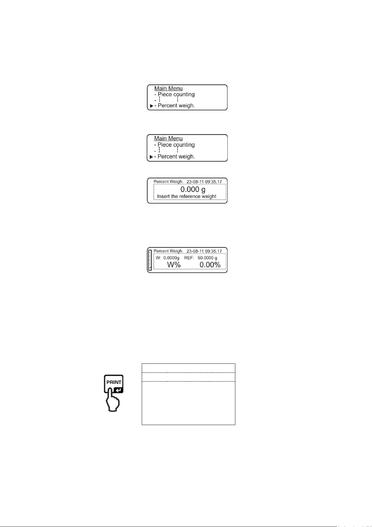
12.5.2 Introducing the reference weight in the numerical value
07-09-20 11:14:57
Proz.
49.95%
Weight:
9.990 g
Refer. :
20.000 g
Using the navigation buttons , select the menu item <Percent weigh.>.
Confirm by pressing the PRINT button, the currently set mode will be displayed.
Using the navigation buttons , select the “Manual” setting.
Confirm, pressing PRINT.
Using the navigation buttons (see chapter 3.2.2), enter the reference weight
(100%) in grams.
Confirm the entry, pressing the PRINT button.
From now on, the scale is in the percentage value determination mode.
Place the weighed material. The result will be displayed.
W% Percentage sample weight
W: Sample weight in grams
REF: Reference weight (100%)
Once the optional printer is connected, the displayed value can be printed.
Sample printout (KERN YKB-01N):
Percentage sample weight
Sample weight in grams
Reference weight (100%)
Return to the weighing mode
Press the ON/OFF button.
TALJG_A/TALSG_A/TPLJG_A/TPLSG_A-BA-e-2112 85
Page 86

12.6 Weighing a nimals
07-09-20 11:14:57
Time
= 20 Sek
A:
20.0052 g
The animal weighing function can be used for uncalm weighing. The mean value of
the weighing results will be calculated in a preset timeframe.
The less stable the weighed material is, the longer timeframe should be selected.
In the weighing mode, press the MENU button. The main me nu is di spl ayed.
Using the navigation buttons , select the menu item <Animal weigh.>.
Confirm by pressing the PRINT button, the currently set time measurement will be
displayed.
Using the navigation buttons , select the required time (5–90s) and confirm by
pressing the PRINT button.
Place the weighed material and press the PRINT button. The countdown of the
preset measurement time will be displayed (“Countdown”).
The mean weighing result will be displayed.
Once the optional printer is connected, the displayed value can be printed.
Sample printout (KERN YKB-01N):
Measurement time
Weighing result
To carry out consecutive weighing once, press the ON/OFF button.
Return to the weighing mode:
Press the ON/OFF button twice.
86 TALJG_A/TALSG_A/TPLJG_A/TPLSG_A-BA-e-2112
Page 87

12.7 Peak value f unc tion
button is pressed. The scale is
07-09-20 11:14:57
Max.:
20.0356 g
This function enables to display the highest loading value (peak value) for one
weighing.
The peak value will be displayed until it is deleted.
Using the navigation buttons , select the menu item <Maximum load>.
Confirm, pressing the PRINT button. The taring process will start automatically.
The “Tare” symbol will be displayed for a while.
From now on, the scale is in the peak value determination mode.
Load the scale plate. The highest load will be displayed.
The peak value will be displayed until the TARE
ready for other weighing.
Once the optional print er is connected, the displayed value can be printed.
Sample printout (KERN YKB-01N):
Peak value
Return to the weighing mode:
Press the ON/OFF button.
TALJG_A/TALSG_A/TPLJG_A/TPLSG_A-BA-e-2112 87
Page 88

12.8 GLP function (Good Laboratory Practi c e )
. The symbol will be displayed to enable to enter the
), enter the scale identification
enable to enter the
), enter the user ID (max. 18
), enter the project ID (max. 18
button until the sound signal
In the sett ings of the “GLP” function, the information printed in measurement reports
is defined.
Using the navigation buttons , select the menu item <GLP>.
Confirm, pressing PRINT
scale identification number.
Using the navigation buttons (see chapter 3.2.2
number (max. 18 characters).
Confirm by pressing PRINT. The symbol will be displayed to
user ID.
Using the navigation buttons (see chapter 3.2.2
characters).
Confirm, pressing PRINT. The symbol will be displayed to enable to enter the
project ID.
Using the navigation buttons (see chapter 3.2.2
characters).
To save all information, press and hold the PRINT
stops. The scale will switch to the weighing mode again automatically.
88 TALJG_A/TALSG_A/TPLJG_A/TPLSG_A-BA-e-2112
Page 89

To obtain printouts conforming to the GLP, enable the menu item “PRINT-
07-09-20 11:14:57
Balance ID:
TEST 1
User ID
Miller
Project ID:
789
Weight. 199.991 g
Signature:
GLP button”, see chapter 11.2.
Sample printout (KERN YKB-01N):
GLP parameters
Weighing data
GLP parameters
TALJG_A/TALSG_A/TPLJG_A/TPLSG_A-BA-e-2112 89
Page 90

RS-232C
13 RS-232C interface
A standard scale is equipped with a RS-232C interface used to connect a peripheral
device (e.g. a printer or a computer).
13.1 Technical specification
8-bit ASCII code
8 data bits, 1 stop bit, no transparency bit
transmission speed selected in the range of 1,200–9,6 00 ba uds
Trouble-free operation of the interface is ensured only when the appropriate
interface cable by KERN is used (max. 2 m)
To ensure communication between the balance and the printer, the following
conditions must be met:
• Connect the scale with the printer interface using the appropriate cable.
Trouble-free operation is ensured only when the appropriate interface cable by
KERN is used.
• The scale and printer transmission speeds must be compatible, see
chapter 11.3.
13.2 Use of the scale plug pins
Pin 1: Power +5V
Pin 2: Tx Signal
Pin 3: Rx Signal
Pin 5: GND
90 TALJG_A/TALSG_A/TPLJG_A/TPLSG_A-BA-e-2112
Page 91

13.3 Interface
Scale
PC
Scale
PC
Input data
2
Scale
Printer
Scale
Con
Connector
3
2
Scale
PC
2
2
• Scale–computer, 25-pin plug
side
• Scale–computer, 9-pin plug
side
3
5
6
4
3
5
6
4
2
7
6
20
3
5
6
4
nect
25 Pins
side
• Scale–printer
4
5
Busy signal
GND (weight)
TALJG_A/TALSG_A/TPLJG_A/TPLSG_A-BA-e-2112 91
Page 92

13.3.1 Printer connection
The scale and printer communication parameters must be compatible, see
Protocol templates are presented in chapters concerning relevant
Stabilit
y
Switch the scale and the printer off.
Connect the scale with the printer interface using the appropriate cable.
Trouble-free operation is ensured only when the appropriate interface cable by
KERN is used (optional).
Switch the scale and the printer on.
•
chapter 11.3.
•
applications.
13.4 Data transmission
A record is composed of the following 14 characters:
1st character Value / space (weighing value)
2nd–9th characters Weight or other data
10th–12th
Weight unit
characters
13th character Stabilization indicator
14th character Carriage return
15th character Line feed (next line)
13.5 Data transmission formats
For a stable weight, the format will be sent after the PRINT button is pressed.
The weighing mode (continuous data transfer and remote control command)
1° 2° 3° 4° 5° 6° 7° 8° 9° 10° 11° 12° 13° 14° 15°r
Symbol Weight Weight unit
Density determination (solely the remote control command)
1° 2° 3° 4° 5° 6° 7° 8° 9° 10° 11° 12° 13° 14° 15° 16° 17°
CR LF
d = Density
Space
Weight unit CR LF
92 TALJG_A/TALSG_A/TPLJG_A/TPLSG_A-BA-e-2112
Page 93

Piece count (solely the remote control command)
Number of pieces
1° 2° 3° 4° 5° 6° 7° 8° 9° 10° 11° 12° 13° 14° 15° 16°
Pcs : Space
Number of pieces
Weight of the placed parts
1° 2° 3° 4° 5° 6° 7° 8° 9° 10° 11° 12° 13° 14° 15° 16° 17° 18° 19° 20°
Weight :
Space
Weighing value
Space
g
Space
S
Average part weight
1° 2° 3° 4° 5° 6° 7° 8° 9° 10° 11° 12° 13° 14° 15° 16° 17° 18°
PMU
Average part
weight
: Space Weighing value
Space
g
Percentage value determination (solely the remote control command)
Percentage value
1° 2° 3° 4° 5° 6° 7° 8° 9° 10° 11° 12° 13° 14° 15° 16° 17° 18°
Percent . Space Percent
Space %
Weight value
1° 2° 3° 4° 5° 6° 7° 8° 9° 10° 11° 12° 13° 14° 15° 16° 17° 18°
Weight Space Weight valu e
Space
g
TALJG_A/TALSG_A/TPLJG_A/TPLSG_A-BA-e-2112 93
Page 94

Animal weighing (solely the remote control command)
“T” = H54
Taring
“C” = H43
Adjustment
“E” = H45
Stable weighing value transmission
“M” = H4D
Menu
“O” = H4F
ON/OFF
Time
1° 2° 3° 4° 5° 6° 7° 8° 9° 10° 11° 12° 13° 14° 15° 16° 17° 18°
Time
Space = Space
Time
value
Seconds Space
Mean value
1° 2° 3° 4° 5° 6° 7° 8° 9° 10° 11° 12° 13° 14° 15° 16° 17° 18°
Mean . = Space Mean weight Space g
13.6 Remote cont rol command
Instruction Function
94 TALJG_A/TALSG_A/TPLJG_A/TPLSG_A-BA-e-2112
Page 95

14 Error messages
Unstable weight value or impossible resetting.
Check environmental conditions.
Data transmission impossible as the weight value is unstable.
Check environmental conditions.
Unstable weight value in the density determination mode.
Check environmental conditions.
Erroneous data upload (counti ng the number of pieces, density
determination etc.).
Weighing range exceeded.
Check the scale plate position.
Before you start any works related to the maintenance, cleaning and
repair, disconnect the device from the operating voltage.
ERR01
ERR02 Adjustment error, e.g. unstable environmental conditions.
ERR03 Adjustment error, e.g. incorrect adjustment weight.
ERR04 Too low/unstable unit weight.
ERR05
ERR06
ERR07
ERR08 Internal adjustment error.
“UNLOAD”
“CAL But”
Carry out scale adjustment.
Weighing range exceeded (upwards), the load placed exceeds
the scale weighing range. Remove the load from the scale.
Weighing range exceeded (downwards), e.g. the scale plate
not placed.
15 Maintenance, service and disposal
15.1 Cleaning
Do not use any aggressive cleaning agents (solvents etc.), but clean the device with
a cloth and mild soap solution. The liquid must not get inside the device. After the
cleaning is finished, wipe the device dry using a soft cloth.
Any loose specimen/powder remains can be removed carefully with a brush or a
handheld vacuum cleaner.
Remove any scattered weighed material immediately.
15.2 Maintenance and service
The device can be operated and maintained solely by the technicians trained
and authorized by KERN.
Disconnect from the mains be fore op eni ng .
TALJG_A/TALSG_A/TPLJG_A/TPLSG_A-BA-e-2112 95
Page 96

15.3 Disposal
The weight indicator is not lit
• The scale is not on.
• Interrupted mains connection (mains cable not
connected/damaged).
• Mains voltage failure.
• Batteries/rechargeable batteries
not placed correctly or discharged
• No batteries/rechargeable batteries.
The weight indication
• T able/air vibrations.
• T he scale plate is in contact with foreign bodies.
interfering device).
The weighing result
is clearly wrong.
• Incorrect adjustment.
• T here are heavy temperature fluctuations.
interfering device).
The packaging and the device should be disposed in accordance with the national or
regional law in the location where the device is operated.
16 Help for any minor failures
If there are any programme execution problems, the scale should be switched off and
disconnected from the mains for a while. Next, the weighing process should be
started anew.
Help:
Problem Possible cause
keeps fluctuating.
If there are any other error messages displayed, switch the scale off and then on
again. If the error message persists, contact the manufacturer.
• Draft / air movements.
• Electromagnetic fields / static discharg e (select
another location / if possible, switch off the
• T he scale indication was not reset.
• The heating time not obser ved.
• Electromagnetic fields / static discharge (select
another location / if possible, switch off the
96 TALJG_A/TALSG_A/TPLJG_A/TPLSG_A-BA-e-2112
Page 97

17 Ionizing unit (factory option for KERN ALJ-A03)
The ionizing unit should be used solely with electronic scales. Do not use
Never use the ionizing unit in explosive atmospheres. The standard
the ionizing unit from high humidity of air / temperature, vapors
term heavy moisture. Any
forbidden condensation of the air moisture on the ionizing unit may occur
a cold device is placed in a much hotter environment. In such
circumstances, leave the ionizing unit not connected to the mains for 2
If smoke, burned smell, heavy heating of the ionizing unit occur, or the
red LED is lit, switch the ionizing unit off immediately using the main
voltage technology is used, handle the ion source and
(for model TALJG 210-5-A ioniser as standard)
17.1 General information
The ionizing unit has blades supplied with high voltage. In their immediate vicinity,
there are ions generated with a positive and negative charge as a result of corona
discharge. The ions are attracted by the weighed material with static charge,
neutralizing the interfering static charge. This eliminates also forces falsifying
weighing (e.g. the false weighing result, drifting weighing value).
17.2 Basic safety instructions
WARNING
it for any other purposes.
version is not explosion-proof.
Protect
and dust.
Ensure location free fr om water / oil .
Do not expose the ionizing unit to long-
when
hours to adapt to the ambient temperature.
When the ionizing unit is on, do not touch the ion source, see the label to
the left.
switch and disconnect it from the mains.
If it is discovered water or solid bodies enter the ionizing unit, switch it off
immediately using the main switch and disconnect it from the mains.
As the high-
outputs carefully.
Do not dismount or modify the ionizing unit.
TALJG_A/TALSG_A/TPLJG_A/TPLSG_A-BA-e-2112 97
Page 98

Protect from any
damage resulting from any fall, vibrations or impacts,
Always use the original power supply. The printed voltage value must be
Before you start any maintenance and cleaning, disconnect the ionizing
Ensure periodic maintenance and cleaning of the ionizing unit.
Starting a damaged ionizing unit may result in a short circuit, fire or
outdoors and in vehicles. It invalidates all
If there are any electromagnetic fields, high readout deviations
(erroneous weighing results) may occur. Discharge the sample at a
green LED [POWER] is lit, if the operation is
When the red LED is lit, switch the ionizing unit off immediately using the
main switch and then on again. If the red LED is still lit, contact the
see the label to the left.
consistent with the local mains voltage.
Injury hazard, the ion source blades are very sharp.
The ionizing unit generates toxic ozone, ensure appropriate ventilation.
unit from the mains.
Disconnect the unused ionizing unit from the mains.
CAUTION
Ion source cleaning: after 1,000 hours.
Ion source replacement: After 30,0 00 hours
electric shock.
It is prohibited to start it
warranties.
relevant distance from the sc al e.
In the standard mode, the
disturbed, the red LED [ALARM] is lit.
manufacturer.
During ionizing, the blue LED [ RUN] is lit.
Operation sounds can be heard during the ionizing process.
98 TALJG_A/TALSG_A/TPLJG_A/TPLSG_A-BA-e-2112
Page 99

17.3 Technical specification
“Sample–ion source”
distance
Ozone concentration 0~0.05 ppm (2 cm to the ion source)
Weight 525 g
Dimensions [cm] 110 × 105 × 60
Ambient conditions 0–50°C, air humidity 20–80% (non-condensing)
Power supply
input voltage
Ionizing unit
input voltage
Contamination degr ee 2
Overvoltage category Category II
Installation height
above sea level
Ca. 5–40 cm
100–240 VAC; 50/60 Hz
12 VDC, 500 mA
up to 2000 m
Location site Solely indoors
17.4 Device overview
Keyboard overview
1 Active ion source (Continuous Mode)
(automatic switch off after 8 h)
2 Active ion source (Time Mode)
(2-minute operation mode)
To switch between the operation modes, press one of the two buttons.
TALJG_A/TALSG_A/TPLJG_A/TPLSG_A-BA-e-2112 99
Page 100

Indication overview
Green LED
Ionizing unit
operation
Ionizing unit on
Red LED
operation
Continuous Mode
Blinking red LED
Ionizing unit
Ionizing unit
operation
Time mode
17.5 Start
Connect the ionizing unit to the power supply solely when the device is on.
Switch the ionizing unit on, pressing the button.
The ionizing unit is in the “Continuous Mode”, the operating time is 8 hours. The
red LED is lit. The ionizing unit will be switched off automatically after 8 hours.
Switch the ionizing unit on, pressing the button.
The ionizing unit is in the “Time Mode”. The ionizing unit is on for 2 minutes, the
red LED blinks. The ionizing unit will be switched off automatically after 2 minutes.
The ionizing unit is on, press any button to switch to any other operating mode.
100 TALJG_A/TALSG_A/TPLJG_A/TPLSG_A-BA-e-2112
 Loading...