

Page 1
KERN & Sohn GmbH
Ziegelei 1
E-Mail: info@kern-sohn.com
Tel: +49-[0]7433- 9933-0
Internet: www.kern-sohn.com
Operation manual
Analytical and precision balances
KERN AET,PET,ILT
Version 1.0
01/2014
GB
D-72336 Balingen
Fax: +49-[0]7433-9933-149
AET/PET/ILT-BA-e-1410
Page 2

KERN AET/PET/ILT
Analytical and precision balances
GB
Version 1.0 01/2014
Operating instructi on
Contents
1. BASIC INFORMATION ....................................................................... 6
1.1. Balances AET-DM ................................................................................... 8
1.2. Balances AET series ................................................................................ 8
1.3. Balances PET series ................................................................................ 9
1.4. Balances ILT-NM series ........................................................................... 9
1.5. Balance cleaning .................................................................................. 10
1.6. Plugging to mains ................................................................................. 10
1.7. Connecting peripheral equipment ........................................................... 10
2. BALANCE DESIGN ........................................................................... 11
2.1. Interfaces ............................................................................................ 13
3. STARTUP ......................................................................................... 14
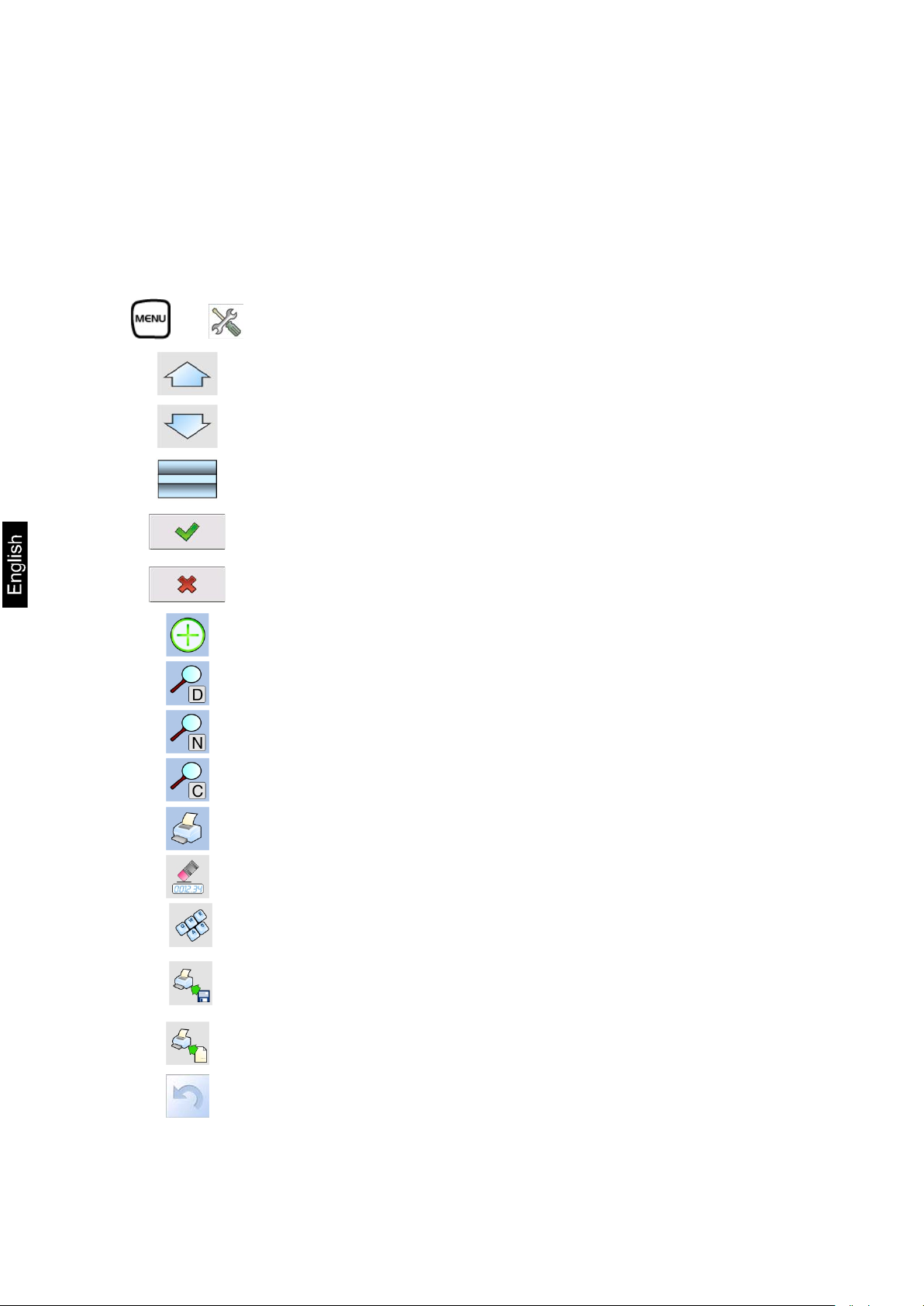
4. BALANCE KEYBOARD – FUNCTION KEYS ......................................... 15
5. SOFTWARE STRUCTURE .................................................................. 16
6. SOFTWARE WEIGHING WINDOW .................................................... 17
7. LOGGING ........................................................................................ 18
8. MOVING IN USER MENU .................................................................. 20
8.1. Terminal’s keyboard ............................................................................. 20
8.2. Return to weighing mode ...................................................................... 21
9. WEIGHING ...................................................................................... 22
9.1. Selection of mea su ring unit ................................................................... 22
9.2. Means of correct weighing procedure ...................................................... 23
9.3. Balance leveling ................................................................................... 24
9.4. Zeroing ............................................................................................... 24
9.5. Tarring ................................................................................................ 25
9.6. Use of air buoyancy correction factor ...................................................... 25
9.7. Additional parameters on weighing process ............................................. 29
9.8. Minimum sample .................................................................................. 31
10. ADJUSTMENT .................................................................................. 35
10.1. Internal adjustment .............................................................................. 35
10.2. External adjustment ............................................................................. 35
10.3. User adjustment .................................................................................. 36
10.4. Adjustment test ................................................................................... 36
10.5. Automatic adjustment ........................................................................... 37
10.6. Automatic adjustment time ................................................................... 37
10.7. Adjustment report printout .................................................................... 37
10.8. GLP project ......................................................................................... 37
10.9. Adjustment history ............................................................................... 38
2 AET_/PET_/ILT_NM-BA-e-1410
Page 3

11. USERS ............................................................................................. 39
12. ACCESS LEVEL ................................................................................. 40
13. PROFILES ........................................................................................ 42
13.1. Creating a profile ................................................................................. 42
13.2. Profile structure ................................................................................... 43
13.2.1. Settings ....................................................................................... 44
13.2.2. Working modes ............................................................................. 44
13.2.3. Readout ....................................................................................... 45
13.2.4. Measuring units ............................................................................ 46
14. WORKING MODES – general information ........................................ 47
14.1. Worki n g mode selection ........................................................................ 48
14.2. Quick access keys ................................................................................ 49
14.3. Information ......................................................................................... 50
14.4. Printouts ............................................................................................. 50
14.5. Profiles ............................................................................................... 53
15. PARTS COUNTING ........................................................................... 54
15.1. Additional settings of part counting mode ................................................ 55
15.2. Parts counting – quick access keys ......................................................... 56
15.3. Setting standard (reference) mass by inserting determined part mass ........ 56
15.4. Setting standard (reference) mass by weighing ........................................ 56
15.5. Acquiring part mass from database......................................................... 57
15.6. Updating part mass in the database ........................................................ 58
15.7. Part counting procedure ........................................................................ 58
15.8. Checkweighing function in parts counting mode ....................................... 59
15.9. Dosing function in parts counting mode ................................................... 60
16. CHECKWEIGHING............................................................................ 61
16.1. Use of checkweighing thresh olds ............................................................ 62
16.2. dditional settings of checkweighing mode ................................................ 62
17. DOSING .......................................................................................... 63
17.1. Use of database of products in dosing process ......................................... 64
17.2. Additional settings of dosing mode ......................................................... 65
18. PERCENT SETUP .............................................................................. 66
18.1. Comparison of sample and (reference) mass standard .............................. 67
18.2. Checkweighing, dosing functions in percent setup mode ............................ 68
18.3. Interpreting the function by use of a bargraph ......................................... 69
18.4. Additional settings of Percent Setup mode ............................................... 69
19. DENSITY ......................................................................................... 70
19.1. Determining density of solid object ......................................................... 71
19.2. Density determining of liquids ................................................................ 72
19.3. Density of air ....................................................................................... 73
19.4. Additional settings of Density mode ........................................................ 74
19.5. Printouts ............................................................................................. 75
19.6. Report from completed density determination processes ........................... 78
20. ANIMAL WEIGHING ........................................................................ 79
20.1. Setting of animal weighing mode............................................................ 80
20.2. Additional settings of animal weighing mode ............................................ 81
AET_/PET_/ILT_NM-BA-e-1410 3
Page 4

21. FORMULATION ................................................................................ 82
21.1. Additional settings of formulation mode .................................................. 83
21.2. Formulation – quick access keys ............................................................ 84
21.3. Adding formulas to the Database of Formulas .......................................... 84
21.4. Using formulas in weighing .................................................................... 86
21.5. Printouts ............................................................................................. 88
21.6. Report from completed formula making processes .................................... 90
22. STATISTICS .................................................................................... 91
22.1. Setting of keys and workspace for Statistics mode ................................... 92
22.2. Additional settings of Statistics mode ...................................................... 92
22.3. Parameters related to a series of measurements ...................................... 93
23. PIPETTE CALIBRATION ................................................................... 95
23.1. Additional settings of pipettes calibration mode ........................................ 97
23.2. Pipettes calibration – quick access keys .................................................. 97
23.3. Adding a pipette to the Database of Pipettes ............................................ 98
23.4. Printouts ............................................................................................. 99
23.5. Working mode activating procedure .......................................................100
23.6. Report from completed calibration processes ..........................................101
24. DIFFERENTIAL WEIGHING ............................................................ 103
24.1. Additional settings of differential weighing mode .....................................104
24.2. Differential weighing – quick access keys ...............................................104
24.3. Introducing a series to the Database of Series ........................................106
24.4. An example of process for differential weighing mode ..............................107
24.5. Copy tare ...........................................................................................113
24.6. Using option “SAMPLE SELECTION”........................................................114
24.7. Deleting a value ..................................................................................114
24.8. Printouts ............................................................................................115
25. STATISTICAL QUALITY CONTROL – SQC ....................................... 117
25.1. Working mode activating procedure .......................................................118
25.2. Additional settings of the SQC mode ......................................................120
25.3. Carrying out a control process ..............................................................120
25.4. Report from product control ..................................................................122
27.1. Processes carried out on databases .......................................................128
27.2. Products .............................................................................................128
27.3. Weighing records ................................................................................130
27.4. Clients ...............................................................................................131
27.5. Formulation ........................................................................................131
27.6. Reports from formulation .....................................................................132
27.7. Reports from density ...........................................................................133
27.8. Pipettes .............................................................................................134
27.9. Reports from pipette calibration processes .............................................134
27.10. Series ............................................................................................135
27.11. A report from SQC...........................................................................136
27.13. Ambient conditions ..........................................................................139
27.14. Packages........................................................................................140
27.15. Warehouses ...................................................................................140
27.16. Printouts ........................................................................................141
4 AET_/PET_/ILT_NM-BA-e-1410
Page 5

27.17. Universal variables ..........................................................................143
27.18. Delete data older than .....................................................................143
27.19. Export database of weighing records to file ........................................144
28. COMMUNICATION ......................................................................... 145
28.1. RS 232 port settings ............................................................................145
28.2. ETHERNET port settings .......................................................................145
28.3. TCP protocol settings ...........................................................................146
29. PERIPHERAL DEVICES................................................................... 146
29.1. Computer ...........................................................................................146
29.2. Printer ...............................................................................................147
29.3. Barcode scanners ................................................................................148
29.4. Transponder card reader ......................................................................148
29.5. Additiona l display ................................................................................149
30. INPUTS / OUTPUTS ....................................................................... 151
31. OTHERS......................................................................................... 153
31.1. Interface language ..............................................................................153
31.2. Data and time setting ..........................................................................153
31.3. “Beep” sound ......................................................................................153
31.4. Touch panel calibration ........................................................................154
31.5. Level c on t r ol .......................................................................................154
31.6. Sensor sensitivity ................................................................................155
31.7. Autotest .............................................................................................155
32. SYSTEM INFORMATION ................................................................. 161
33. COMMUNICATION PROTOCOL ....................................................... 161
33.1. A set of commands ..............................................................................162
33.2. Responses format for commands sent from computer level ......................163
33.3. Manual printout / Automatic printout .....................................................170
34. CONNECTING PERIPHERAL DEVICES ............................................. 171
35. DIAGRAMS OF CONNECTING CABLES ............................................ 171
36. ERROR MESSAGES ......................................................................... 172
37. APPENDIX A – Variables for printouts........................................... 173
37.1. List of variables ...................................................................................173
37.2. Variables formatting ............................................................................182
38. APPENDIX G – Menu structure ...................................................... 184
39. Declaration of -Conformity ............................................................ 189
AET_/PET_/ILT_NM-BA-e-1410 5
Page 6

1. BASIC INFORMATION
INTENDED USE
Balances are intended to precise mass measurement of weighed loads
conducted in laboratory conditions.
PRECAUTION MEASURES
Before first use of the balance, it is highly recommended to carefully
read this User Manual, and operate the balance as intended.
Do not operate the touch panel using sharp edged tools (knife,
screwdriver, etc.).
Place weighed loads on the center of balance’s weighing pan.
Load the balance’s weighing pan with loads that gross mass does not
exceed instrument’s measuring range (maximal capacity).
Do not leave heavy loads on balance’s weighing pan for a longer period
of time.
In case of defect immediately unplug the instrument from mains.
Balances to be decommissioned, should be decommissioned in
accordance to valid legal regulations.
Do not use the balance is areas endangered with explosion. Balance Y2
series is not designed to operate in EX zones.
WARRANTY CONDITIONS
A. Defining defects of unclear origin defects and means of their elimination can
only be realized with assistance of manufacturer and user representatives,
B. Warranty does not cover:
• Mechanical defects caused by product exploitation other than intended,
defects of thermal and chemical origin, defects caused by lightning,
overvoltage in the power netw ork or other random event,
• Balance defects if it is utilized contrary to its intended use,
• Balance defects, if service claims removing or destroying product’s
protective stickers which protect the balance’s housing against
unauthorized access.
6 AET_/PET_/ILT_NM-BA-e-1410
Page 7

• Mechanical defects or defects caused by liquids and natural wear,
• Balance defects caused by inappropriate setting of a defect of electric
power network,
• Defects caused by overloading balance’s mechanical measuring system,
• Maintenance activities (cleaning).
C. Loss of warranty takes place if:
• Service claims intrusion into mechanical or electronic construction by
unauthorized people ,
• Other version of the operating system is installed in a balance,
• The balance does not bear company’s protective stickers.
D. Detailed warranty conditions are listed on a service card.
Supervision over balance’s metrological parameters
Metrological parameters of a balance need to be checked by a user in
determined time intervals. Inspection frequency is conditioned by ambient
conditions in which a balance is used, kind of carried out processes and
adopted quality management system.
The manual’s significance
It is very important to read the user manual carefully before switching on and
starting up balance operation, even if the user is experienced and has worked
with the this type of balance before.
Balance user training
A balance should be utilized and supervised only by users who are trained and
experienced in such type of weighing instruments.
AET_/PET_/ILT_NM-BA-e-1410 7
Page 8
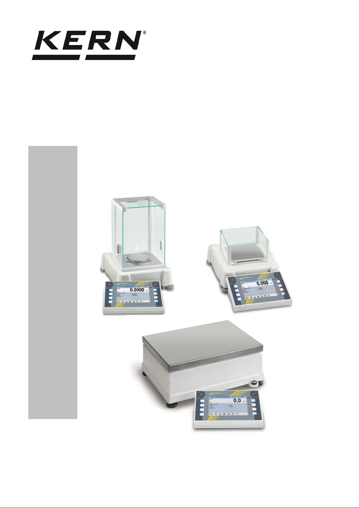
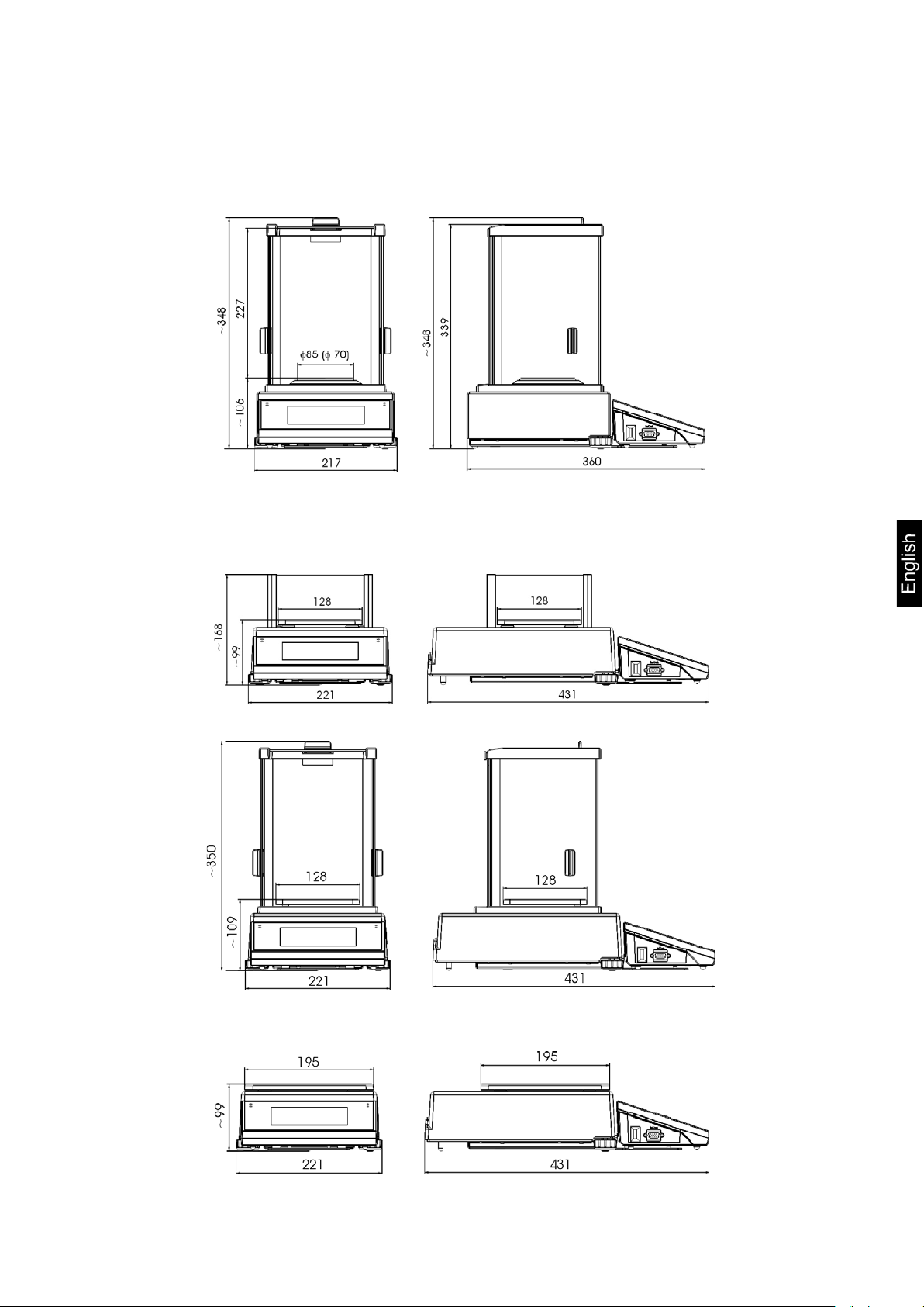
Analytical balances AET series
back of balance’s housing.
1.1. Balances AET-DM
1.2. Balances AET series
AE-DM analytic balances
A – balance with d=0,01mg unit
B – balance with d=0,1mg unit
After balance installing at operating place,
following should be set:
1 – bottom ring
2 – balance pan
3 – pan shield
After the elements setting, additional
devices should be connected and balance
should be plugged to power source. Power
socket is located on back side of balance
housing.
Pipettes calibration
Remove the pan and put on its place:
- pipettes calibration chamber
- inside the chamber, pan and other
elements should be set up.
Carefully remove the balance from its packaging, remove the plastic and foil
transport protective elements. Gently place the balance in its intended place of
use. Install the weighing pan, and other elements according to below scheme.
A – balance with reading unit
d=0,01mg
B – balance with reading unit
d=0,1mg
On installing the balance in its
intended place of use, assembly:
1 – bottom shield of the weighing
chamber
2 – centering ring
3 – weighing pan
4 – pan shield
On assembling all components,
connect peripheral devices to the
balance, and plug the balance to
mains. Power socket is located at the
8 AET_/PET_/ILT_NM-BA-e-1410
Page 9
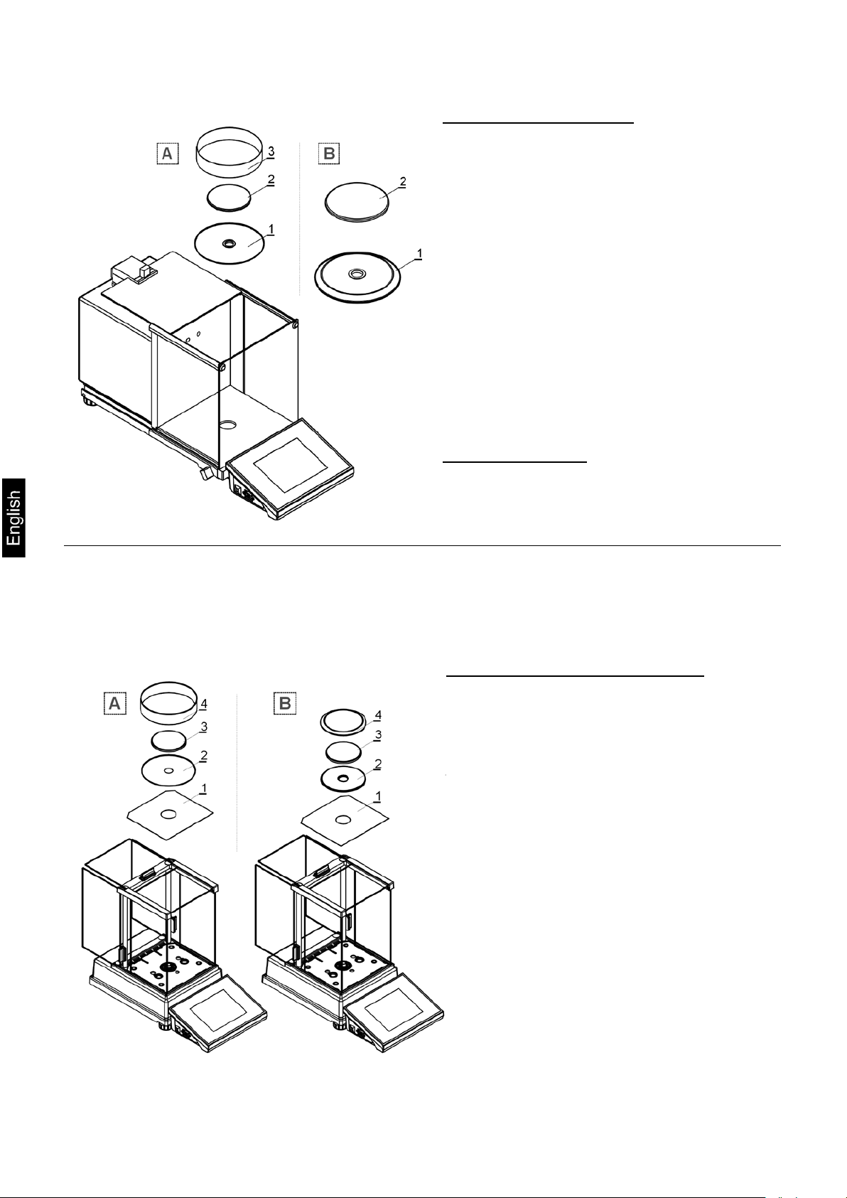
Precision balances PET series
back of balance’s housing.
After unpacking unscrew bolt 1 which locks the
1.3. Balances PET series
Carefully remove the balance from its packaging, remove the plastic and foil
transport protective elements, and gently place the balance in its intended
place of use. Install the weighing pan, and other elements according to below
scheme.
A – balance with reading unit d=1mg
B – balance with reading unit d=10mg
On installing the balance in its
intended place of use, assembly:
1 – weighing pan mandrels
2 – weighing pan
3 – pan shield /in case of d=1mg/
On assembling all components,
connect peripheral devices to the
balance, and plug the balance to
mains. Power socket is located at the
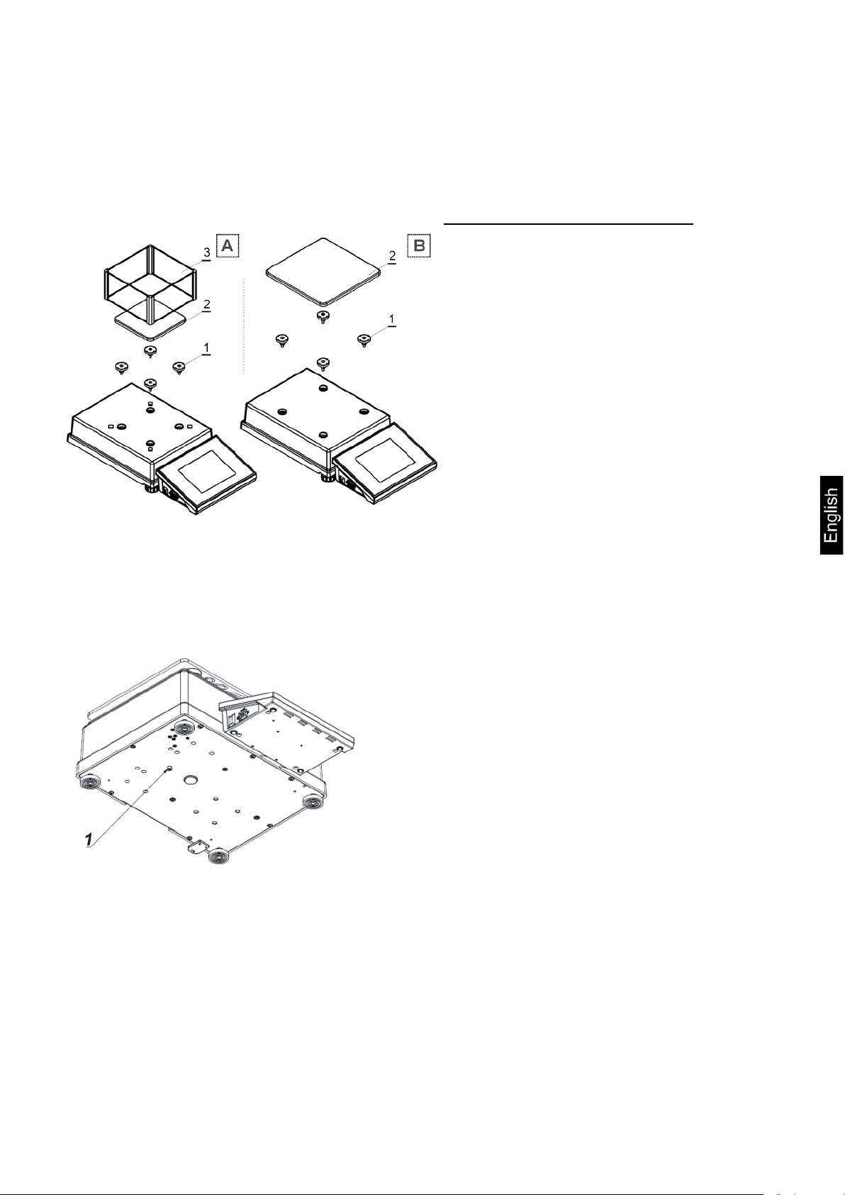
1.4. Balances ILT-NM series
Gently take the balance out of its packaging, remove plastic, carton, foil and
transport protections, and gently place the balance in its intended place of use.
adjustment mechanism.
AET_/PET_/ILT_NM-BA-e-1410 9
Page 10
Before installing the balance in its intended place
On removing the protections and assembling the
of use, remove transp ort protections (1) an d
assembly the weighing pan (2).
On assembling the components, connect all
peripheral devices to the balance and then plug
the instrument to the mains. Power socket is
located at the back of balance’s housing.
weighing pan, connect the terminal to the socket
located at the back of balance’s housing, and
connect all peripheral devices. Only then plug the
balance to mains (mains socket is located at the
back of balance’s housing).
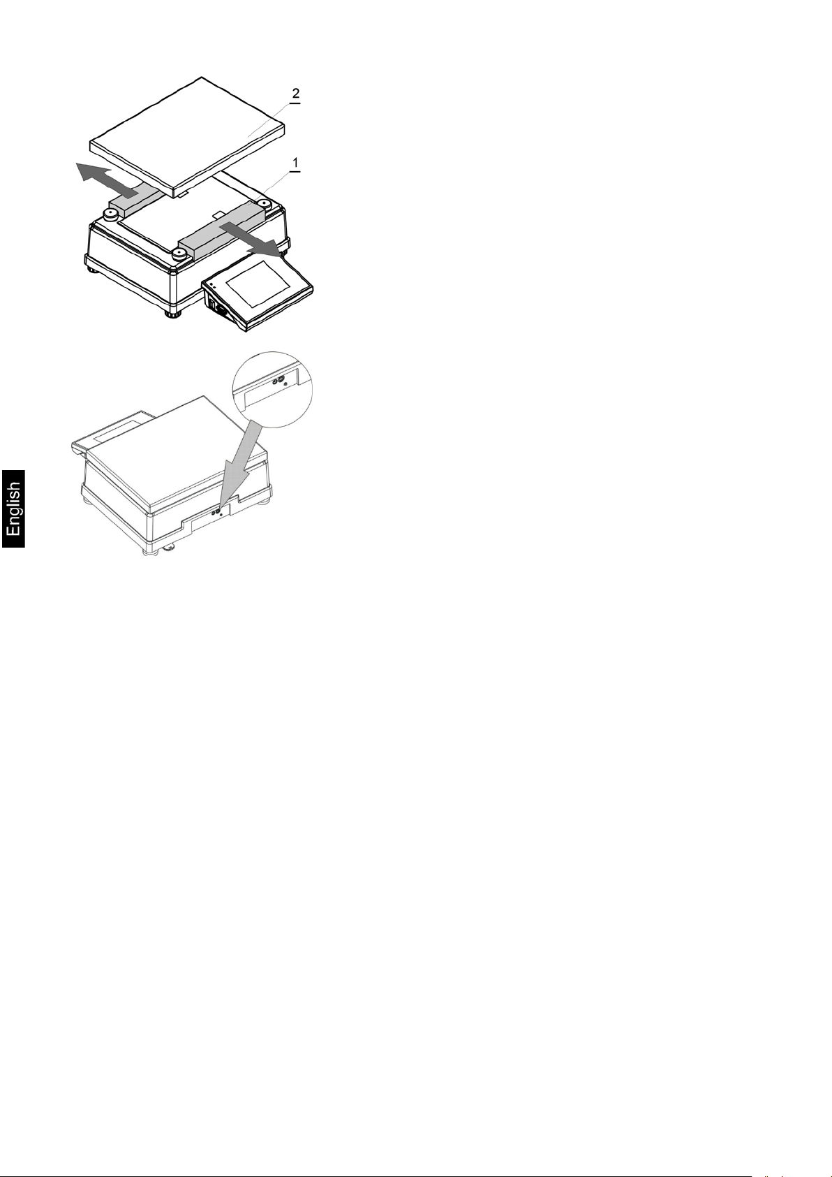
1.5. Balance cleaning
Clean the balance using a damp cloth by gentle rubbing contaminated places.
Remember to remove the weighing pan and its shields from the weighing
chamber before their cleaning.
CAUTION:
Cleaning balance’s weighing pan if installed may damage instrument’s measuring
mechanism.
1.6. Plugging to mains
The balance should be plugged to mains using the original power adapter,
which is balance’s standard equipment. Plug the power adapter’s plug to
balance’s socket located at the back of the housing.
1.7. Connecting peripheral equipment
Use only accessories and peripheral equipment recommended by the
manufacturer of your balance. The balance must be disconnected from the
mains before connecting or disconnecting any peripherals (printer, PC
computer, computer keyboard). On connecting the peripherals, plug the
balance to mains.
10 AET_/PET_/ILT_NM-BA-e-1410
Page 11
2. BALANCE DESIGN
Balance AET-NM series
Balance PET series
AET_/PET_/ILT_NM-BA-e-1410 11
Page 12
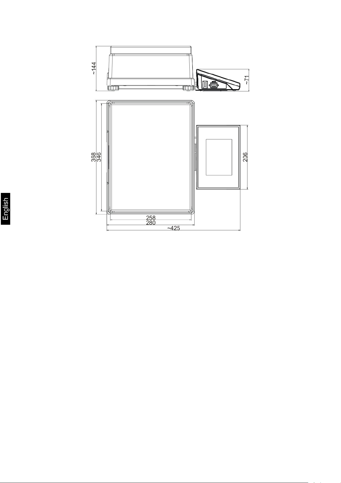
Balance ILT-NM series
12 AET_/PET_/ILT_NM-BA-e-1410
Page 13
3 – USB port
2.1. Interfaces
Description of available interfaces
1 – Ethernet RJ45
2 – RS232 interface (COM1)
4 – IN / OUT, RS232 (COM2)
Interfaces RS232 and IN/OUT
RS232 - socket DB9/M (male), front view:
Pin2 - RxD
Pin3 - TxD
Pin5 - GND
IN/OUT, RS232 socket DSUB15/F (female), front view:
Pin1 - GNDWE
Pin2 - OUT1
Pin3 - OUT2
Pin4 - COMM
Pin5 - 6÷9VDC
Pin6 - IN4
Pin7 - IN3
Pin8 - TxD2
Pin9 - 5VDC
Pin10 - GNDRS
Pin11 - IN2
Pin12 - IN1
Pin13 - RxD2
Pin14 - OUT4
Pin15 - OUT3
AET_/PET_/ILT_NM-BA-e-1410 13
Page 14

3. STARTUP
• On plugging the balance to mains, instrument’s diode ON/LOAD
located on indicator’s housing is lit up.
• Press powering key located on the upper left section of terminal’s
overlay. Within a few seconds, the OS Windows CE and software start
loading, which is signaled by flickering red diode ON/LOAD.
• On completing the startup procedure, the instrument’s displays main
window of the balance software.
• The balance starts up with no user logged in. In order to start operation,
a user has to log in. (logging procedure is described further in this user
manual).
CAUTION: Remember to start the balance with no load on the weighing pan.
14 AET_/PET_/ILT_NM-BA-e-1410
Page 15
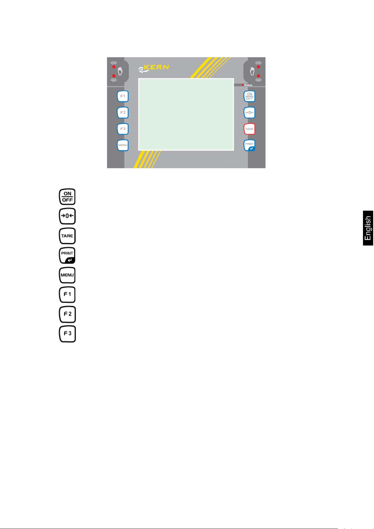
Key
Description
Sending measurement result to a plugged printer or
computer
4. BALANCE KEYBOARD – FUNCTION KEYS
Switching the instrument ON / OFF
Zeroing
Tarring
Function key (entering instrument’s menu)
Working mode selection, (programmable key)
User profile selection, (programmable key)
Internal adjustment, (programmable key)
AET_/PET_/ILT_NM-BA-e-1410 15
Page 16
ADJUSTMENT
USERS
PROFILES
DATABASES
COMMUNICATION
PERIPHERALS
INPUTS/OUTPUTS
ACCESS LEVEL
OTHERS
UPDATE
INFORMATION ON
SYSTEM
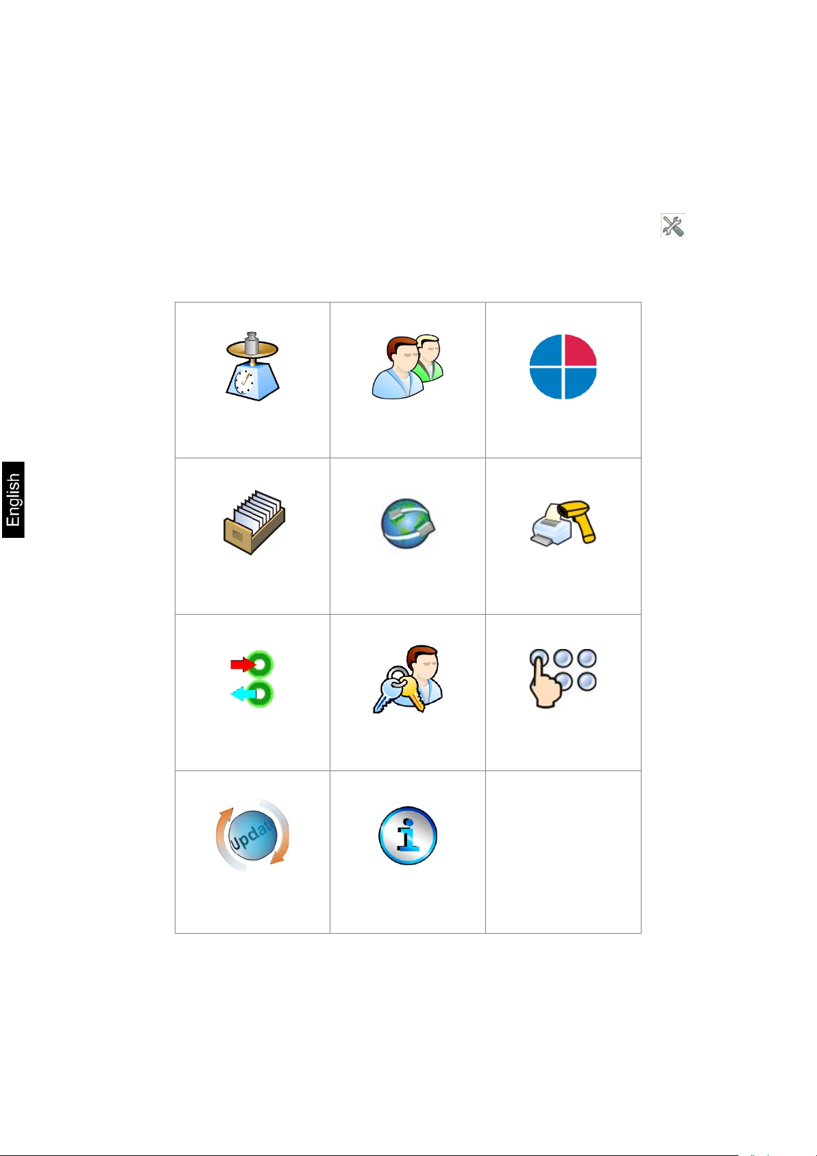
5. SOFTWARE STRUCTURE
The structure of balance’s main menu is divided into function groups. Each
group comprises parameters grouped by their reference. Description of each
menu group is provided further in this user manual.
List of groups - Parameters
Balance’s main menu is accessed by pressing SETUP function key or soft
key located in the bottom tool bar of balance’s display. The menu comprises
parameters referring to balance settings, functions and profiles.
16 AET_/PET_/ILT_NM-BA-e-1410
Page 17
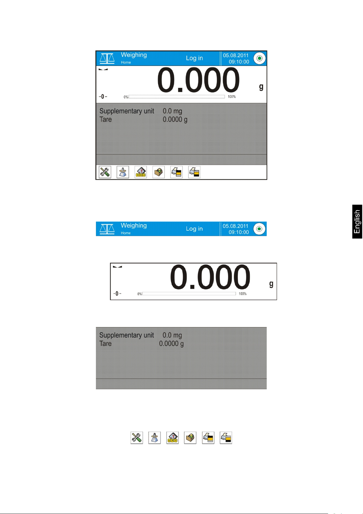
6. SOFTWARE WEIGHING WINDOW
The software’s main window is divided into 4 main sections:
• The upper part of the touch panel displays data on active working mode,
logged operator, date, time, active connection to a computer and current
level status of a balance.
• Below there is a weighing window, indicating measurement result and
current measuring unit
• Under which there is a grey coloured workspace containing additional data
on weighing process and activities
Caution:
Data contained in the workspace is optionally configurable.
Configuring process is described in point 14.3 of this user manual;
• Below the workspace there is a set of soft keys:
Caution:
Balance user can declare the presence of function (quick access) keys. Declaring
process is described in point 14.2 of this user manual;
AET_/PET_/ILT_NM-BA-e-1410 17
Page 18
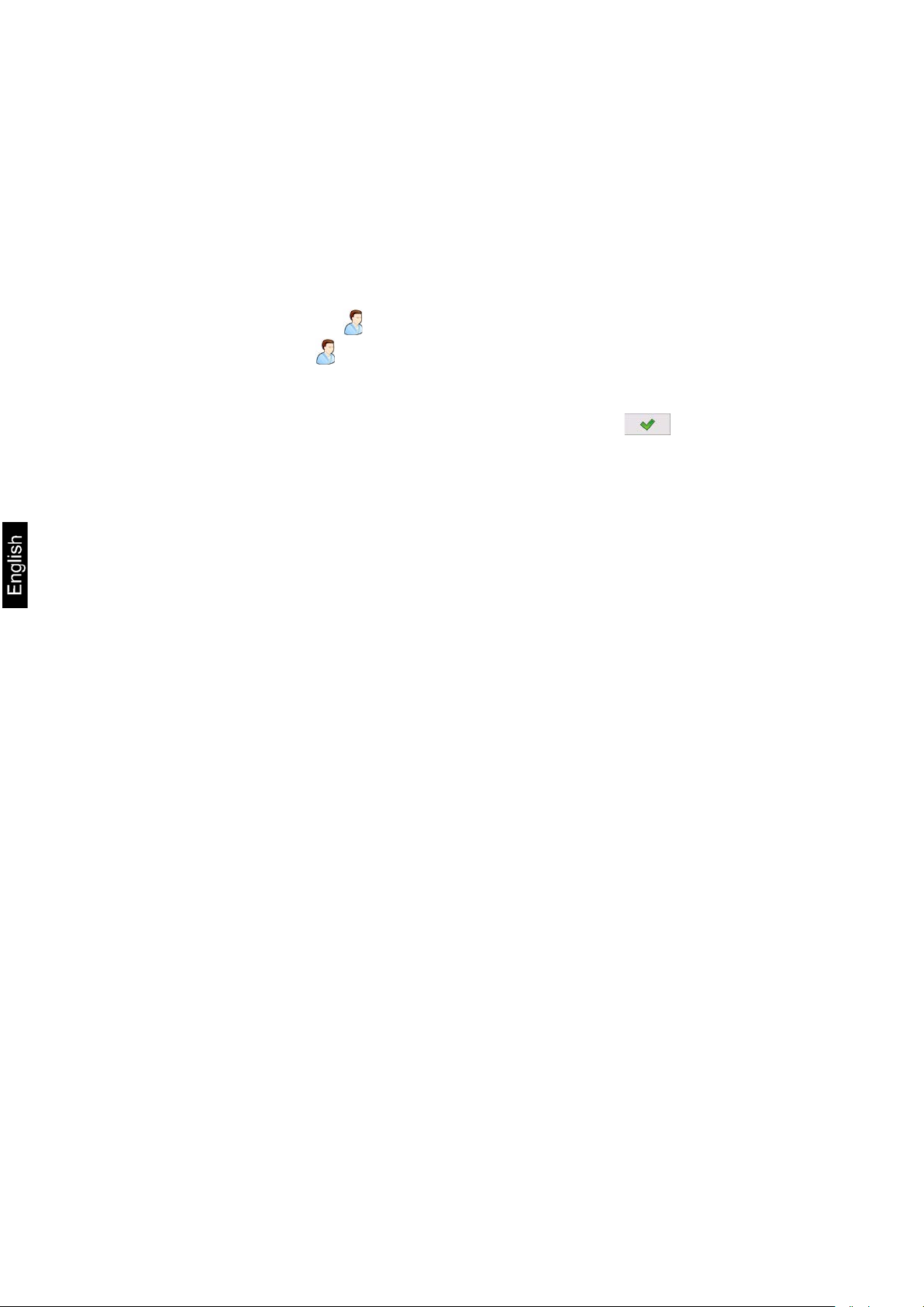
7. LOGGING
Full access to balance’s parameters and editing databases requires logging to
instrument’s software as an operator with <Administrator> access level. The
logging procedure should be carried out on each switching on the balance.
Log in procedure
• While in main weighing window of the application, press <Log in> text
located in the upper window bar, which opens a window with operators
database including < Admin> entry,
• On entering the < Admin> entry, the software activates on-screen
keyboard for entering operator’s password,
• Insert password “1111” and accept it by pressing key,
• The software automatically returns to displaying the main window, and
the display’s upper bar indicates word <Admin> instead of <Log in>,
• After first logging in, the administrator should add user profiles and set
their corresponding access level (the procedure of assigning access levels
is described further in this user manual, see point 12 and 13).
On future logging in, select a user from the list, and on entering password
balance’s software initiates operation with access level set for a
corresponding user.
Log out procedu re
• While in main weighing window of the application, press name of a logged
operator located in the display’s upper bar. A window with operators
database is opened,
• Press <Log out> soft key (located as position no. 1 in the list of
operations)
• The software returns to the main window, and the display’s upper bar
indicates word <Log in> instead of name of a logged operator.
18 AET_/PET_/ILT_NM-BA-e-1410
Page 19
Authorization
Access level
None (guest)
No access to editing all of user parameters.
No access to menu <Databases>.
Operator
Access to editing parameters in submenu: <Profiles;
Advanced
Access to editing parameters in submenu: <Profiles;
Administrator
Access to all user parameters, functions and editing
Access level
Software of balances provides four access levels: administrator, advanced
operator, operator and none (anonymous logg ing).
On switching on the balance, its display is constantly active, enabling carrying
out mass measuring processes. These measurements, however, cannot be
saved in balance’s database unless a user with at least minimal access level is
logged in. The minimal access level enables carrying out mass measuring
processes and saving them in balance’s databases using available function
keys.
Below table indicates access to editing user parameters, databases
and software functions depending on active access level.
it is not possible to accept a weighing record nor to start
a process.
Readout> and settings in group of parameters
<Others>, except for <Date and Ti me>. The operator
can start and carry out all weighing processes, and has
access to <Export weighing database to a file> and
preview data in <Databases>. An operator can define
universal variables.
operator
Readout>; <Working modes>; <Communication>;
<Peripherals>; <Others> except for <Date and Time>.
The advanced operator can start and carry out all
weighing processes, and can erase old data from the
<Databases>.
databases.
AET_/PET_/ILT_NM-BA-e-1410 19
Page 20
Reading printout template from a file format *.lb
device to terminal’s USB port
8. MOVING IN USER MENU
Moving in menu of balances is intuitive.
The touch panel makes the operation of balance’s software very simple.
Pressing a function key, a soft key or area on the display initiates an assigned
function or process.
8.1. Terminal’s keyboard
or
Enter main menu
Scroll menu upwards
Scroll menu downwards,
Fast up and down menu scrolling,
Accept changes,
Leave a function unchanged (without saving changes),
Add items to a database,
Search for items in a database by date
Search for items in a database by name
Search for items in a database by code
Printout of an item from a database
Clear the editing field
Activate / deactivate on-screen keyboard
(function key is active on plugging a data storage
Selection of variables from a list for a printout
Moving (exiting) one level up in menu structure
20 AET_/PET_/ILT_NM-BA-e-1410
Page 21

8.2. Return to weighing mode
Changes in instrument’s memory are saved permanently on returning to
weighing mode.
Procedure:
- Press key for a few times, until the display indicates to the weighing
mode.
- press soft key in the upper bar on the display. The software
immediately returns to displaying the main window.
AET_/PET_/ILT_NM-BA-e-1410 21
Page 22
Verified
balance
9. WEIGHING
Load a weighed object on balance’s weighing pan. On stabilization of weighing
result, indicated by stability marker visible on the side of balance’s display,
read the measurement result.
Saving / printout of the measurement result is available on pressing <PRINT>
key:
• In case of verified balances – only stable measurement result can be
saved or printed (stability marker visible on balance’s display)
• In case of non-verified balances – stable or unstable measurement
result can be saved or printed (regardless of stability marker
presence). If unstable measurement result is printed then it is
accompanied by question mark <?> in front of printed mass value.
9.1. Selection of measuring unit
Change of measuring unit is carried out by pressing the measuring unit icon
visible next to the value of measurement result on balance’s display. Pressing
the measuring unit icon opens a list with available units. On selecting one of
them, the software automatically calculates the indicated mass value to the
active measuring unit.
Available measuring units:
Unit denotation
gram [g] yes
milligram [mg] yes *
kilogram [kg] yes *
carat [ct] yes *
pound [lb] no
ounce [oz] no
ounce Troy [ozt] no
pennyweight [dwt] no
Taele Hongkong
Taele Singapur [tls] no
Taele Tajwan [tlt] no
Momme [mom] no
[tlh] no
Grain [gr] no
Newton [N] no
Tical [ti] no
22 AET_/PET_/ILT_NM-BA-e-1410
Page 23
YES
NO
YES
NO
NO
NO
* - Accessibility of measuring units is conditioned by type of balance and its
verification status.
In non-verified balances all measuring units including those outside the
International System of Units are available.
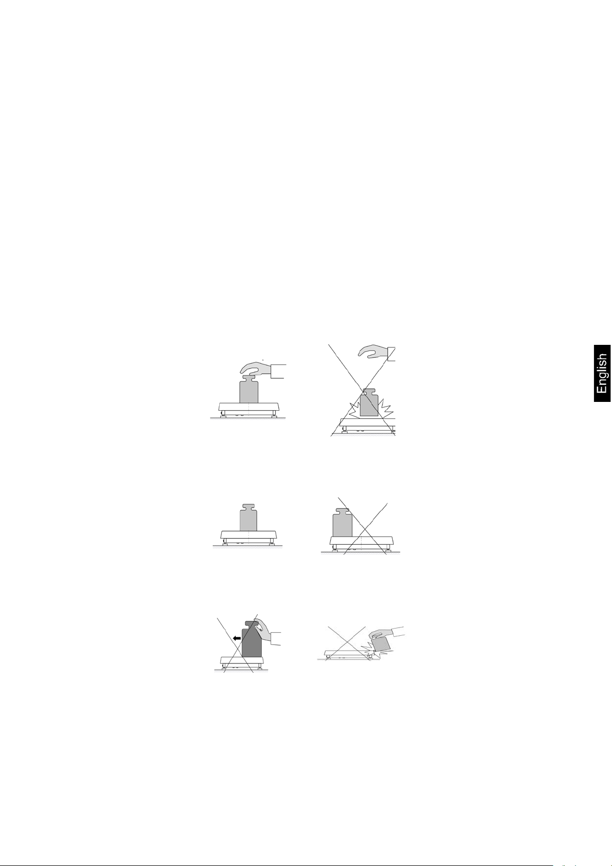
9.2. Means of correct weighing procedure
In order to ensure long lasting use of a balance, correct and reliable
measurement of weighed loads, follow below procedures:
Start the balance with no load on the weighing pan
(permissible value of load on the weighing pan on balance start is
±10% of its maximal capacity).
Load balance’s weighing pan steadily with no shocks:
Place weighed loads centrally on the weighing pan:
Avoid side loading, in particular side shocks:
AET_/PET_/ILT_NM-BA-e-1410 23
Page 24
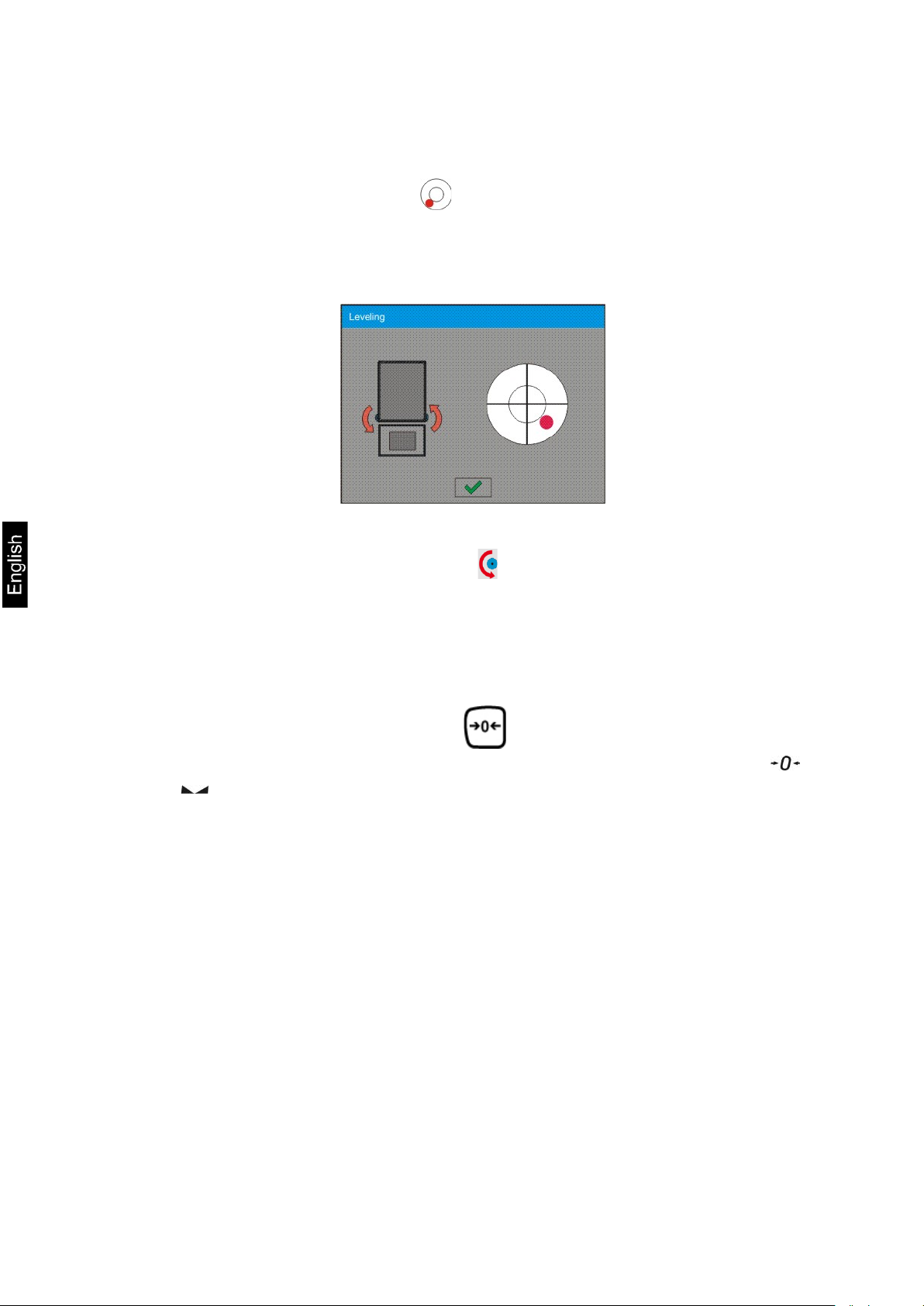
9.3. Balance leveling
Balance leveling procedure
• Press level status pictogram < > located in the upper right corner of the
display.
• The display indicates a control panel of leveling function. Balance operator
previews level status, and balance’s top elevation.
• Level the balance by turning the adjustable feet in a way indicated by
blinking pictograms on the display < > – the level point should move
towards the center of the level circle.
• As the level point is in the center point, its colour changes from red to
green – which is a confirmation for correct level status.
9.4. Zeroing
In order to zero mass indication press key.
The mass indication on the display should equal zero, and precise zero and
stability markers should appear.
Zeroing process is tantamount to determining new zero point recognized by
the balance as precise zero. Zeroing is possible only in stable status of display
indication.
Caution:
Zeroing the display indication is possible only within the ±2% range of
instrument’s maximal capacity. If zeroed value is above the ±2% of the
maximal capacity, then the software indicates an error message Err2.
24 AET_/PET_/ILT_NM-BA-e-1410
Page 25
9.5. Tarring
In order to determine net weight of a weighed object, place object’s container
(packaging) on balance’s weighing pan, and on stabilization of measurement
result press key. The display should indicate mass equal to zero and
symbols: Net and . On taking off the weighed load and its packaging from
instrument’s weighing pan, the display indicates sum of total tarred mass with
minus sign.
The software also enables assigning tare value to a product from a database.
Then, on product selection from a database, the software automatically
uploads data on tare value for the specific pro duct.
Caution:
Tarring negative values is impossible. On tarring negative values the balance
responds with an error message. In such case zero balance’s indication and repeat
tarring procedure.
Manual tare determination
Procedure:
• While in optional mode press quick access key ,
• Which opens numeric keyboard on balance’s display,
• Using numeric keys insert desired tare mass and press key,
• The balance returns to weighing mode, and the display indicates inserted
tare value with minus “–“ sign.
Deleting tare
The tare value indicated on balance’s display can be deleted by pressing ZERO
key on balance’s front panel, or using programmable function key <Deactivate
tare>
PROCEDURE 1 – on taking the tarred load off balance's weighing pan
• Press ZERO key
• The NET marker is deleted, and new zero point of the balance is determined
PROCEDURE 2 – when the tarred load in on balance’s weighing pan
• Press ZERO key
• The NET marker is deleted, and new zero point of the balance is determined
• If tare value exceeds 2% of balance’s maximal capacity, the display
indicates error message –Err- (forbidden operation)
PROCEDURE 3 - when the tarred load in on balance’s weighing pan or on
taking the tarred load off balance's weighing pan
• Press programmable key <Deactivate tare>
• The NET marker is deleted,
• The display indicates tare value
• Press <Restore tare> key to restore the last tare value
9.6. Use of air buoyancy correction factor
AET_/PET_/ILT_NM-BA-e-1410 25
Page 26
Sample mass [g]
The application enables correcting mass measurement errors during:
1. Weighing loads that density considerably differs from the density of
standard used to adjusting the balance. Regularly, the balance is adjusted
with a steel mass standard with density ~8.0g/cm3 or a brass mass
standard with density ~8.7g/cm3. If loads made of other substances are
weighed, then ratio indicated on below chart should apply.
Below chart presents the value of mass correction in relation to the density
of weighed load, assuming that air density is constant and equals
1.2 kg/m3.
Correction value [mg]
Density of weighed load
Error value in relation to density of weighed sample
2. Testing the changes of sample mass within a few hours’ time, if: sample
mass is relatively constant (minor changes). In such case it is assumed,
that considerable effect on the measurement result rests on air density
changes, which is affected by changes of pressure, temperature and
humidity.
In order to carry out a reliable measurement, apart from being familiar with
relations applying to ambient conditions, an operator should know the measuring
methods, features of tested sample, air density in the laboratory room and
density of weighed sample.
FUNCTIONING
The application provides two ways to use the air buoyancy correction procedure.
26 AET_/PET_/ILT_NM-BA-e-1410
Page 27

1. Inserting the specified value of air density and specified value of weighed
sample density to balance’s memory.
On inserting these values the application automatically calculates the
correction factor for weighed mass and indicates corrected value of
weighed mass on balance’s display.
In order to avoid errors, the corrected mass value is accompanied by <!>
symbol visible on balance’s display and a printout.
2. The application semi-automatically determines the value of air density. The
specified density of the weighed sample is inserted to balance’s memory by
an operator.
Determination of air density is carried out using a set of two mass
standards. One of them is made of stainless steel, and the other of
aluminum. Based on mass indications of the two standards, the software
automatically calculated the air density and saves the value in balance’s
memory on operator’s confirmation. Then the density of weighed sample
has to be inserted to balance’s memory.
On inserting these values the application automatically calculates the
correction factor for weighed mass and indicates corrected value of
weighed mass on balance’s display.
As in case 1, the corrected mass value is accompanied by <!> symbol
visible on balance’s display and a printout.
Air buoyancy correction mode is enabled / disabled from the level of user menu.
The application is operating in weighing mode only.
STARTUP AND OPERATION OF AIR BUOYANCY CORRECTION
PROCEDURE
• While in main window press grey coloured workspace
• Select option <Settings>
• Select parameter < Air buoyancy correct ion>
Accessible settings
- Air buoyancy correction – YES/NO
- Sample density (insert the density value of weighed sample). If an
operator uses products from databases, then on product selection
its density value is automatically uploaded.
- Air density – for selecting the means of inserting the air density
value used for calculating buoyancy correction factor.
AET_/PET_/ILT_NM-BA-e-1410 27
Page 28
Settings:
VALUE – selecting this option opens a window for inserting
determined value of air density (e.g.: determined using other
methods). The inserted value is used to calculating buoyancy
compensation factor. The value is assigned automatically on
carrying out the air density determination (on its completion by
pressing < > key).
ONLINE – selecting this option downloads current air density value
from a connected THB sensor, if such is connected to the balance,
or from internal sensor installed in the balance.
If a balance features both types of sensors (THB module and
internal sensor), then data from the THB module supersedes the
other, and parameters Setup/Ambient Conditions/Ambient
Conditions Module require setting to SAVE or SAVE & ALERTS
mode.
If a balance features only one type of the sensors for temperature,
humidity and pressure recording, then correct ONLINE operati on
requires setting of balance parameters:
− Internal sensors only - Setup/Ambient Conditions/Ambient
Conditions Module set to NONE,
− External THB module only - Setup/Ambient
Conditions/Ambient Conditions Module set to SAVE or
SAVE & ALERTS mode.
Additionally, for correct balance cooperation with the THB mod ule
set port’s transmission parameters to compatible with those of the
THB module. the THB module transmission parameters are detailed
on its data plate.
On returning to the weighing mode, the display indicates an additional symbol
<!>, as indicated on below drawing. From now on the value of indicated mass
is corrected including the air buoyancy compensation factor and sample
density.
The measurement result can only be compensated by a correct value if an
operator inserts to balance’s memory the actual value on the air density and
correct density of weighed sample.
28 AET_/PET_/ILT_NM-BA-e-1410
Page 29

Caution:
If the <AIR BUOYANCY CORRECTION> mod e is set to <ONLINE> value, then
balance display does not indicate pictogram <!> which means that parameter
Setup/Ambient Conditions/Ambient Conditions Module is set to SAVE
or SAVE & ALERTS mode, and there is no physical connection between a
balance and a THB module, or the parameters for communicating the module
with the balance are set incorrectly. In such case plug a THB module to
balance’s ports COM 1 or COM 2 and set appropriate cooperation parameters,
such as specified on module’s data plate.
9.7. Additional parameters on weighing process
Changes in settings of functions related to weighing process can in some
extend program balance reactions.
Procedure:
1. Press grey coloured workspace
2. Balance display indicates menu: Settings, Keys, Information, Printouts,
Profile
3. Press one of available submenu options and select item for modification,
Menu <Settings> - additional options related to weighing mode
Menu <Keys> - defining quick access keys
Menu <Information> - supplementary data on weighing process displayed in
the grey coloured workspace
Menu <Printouts> - selection of printout type
Menu <Profile> - selection of profile, active during balance operation
Menu <SETTINGS> - contains supplementary data on weighing process, such
as:
− Tare mode
• SINGLE,
mass value stored in balance memory on single pressing of TARE key, the
following pressing of TARE key determines new value of tare. Selection of
product or packaging with assigned tare value causes automatic deleting
of previously assigned tare value;
• SUM OF ACTIVE,
totalizing applied tare values for a product or a packaging (resulting
from selecting a product or a packaging from corresponding database)
with a possibility of increasing determined tare value by manual tare
introduced manually using balance’s numeric keyboard. On following
determining of tare value for a product or a packaging, the tare value
introduced manually is deactivated.
• SUM OF ALL,
totalizing all introduced tare values.
AET_/PET_/ILT_NM-BA-e-1410 29
Page 30

• AUTOTARE
Means of operation:
Each first stable measurement result is tarred. The NET pictogram
flashes on the display. The operator can determine net mass of weighed
load. On taking off the load from balance’s weighing pan, and as the
indication returns to autozero zone, the software automatically
deactivates Tare value.
− Automatic footer prin tout
Accessible options:
MODE - No – manual footer printout,
Sum of measurements – the condition for printing a footer is
exceeding mass value set in parameter <Threshold>
Number of measurements – the condition for printing a footer
is carrying out a pre-defined number of measurements (a
batch) set in parameter <Threshold>
THRESHOLD – setting the value of threshold determining footer
printout.
For option <Sum of measurements> the value is determined
in measuring unit [g], and for option <Number of
measurements> the value is not measurable, and determined
by number of carried out measurements.
− Printout mode / printout release
• Function key PRINT / printout release, (manual operation)
Never – printout deactivated
First stable – the first stable measurement is printed
Each stable – all stable measurements are set for printing
Each – printout of all measurements (stable and
unstable), in case of a verified balance only stale
measurement results are printable (as in setting
<Each stable>)
• AUTOMATIC MODE
Never – printout de a cti va t e d
First stable – the first stable measurement result obtained after
placing a load on balance’s weighing pan is recorded,
record of the following measurement result takes
place only on unloading the weighing pan, returning
of the mass indication below set threshold’s value,
and placing another load on balance’s weighing pan
Last stable – accepted is the last stable measurement recorded
before taking the load off the weighing pan. The
record takes place on taking the load off the
balance’s weighing pan, and returning of the mass
indication below set threshold’s value.
• THRESHOLD
mass value obligatory for operation of automatic printout. Set in
grams.
30 AET_/PET_/ILT_NM-BA-e-1410
Page 31

− Printout
Contains type of printout that is related to a working mode. Printout
takes place on pressing PRINT key on balance’s overlay.
Accessible options:
• STANDARD PRINTOUT
Possible declaration of printout content: HEADER, WEIGHING DATA
and FOOTER.
printout components marked as <YES> in the menu are printed on
pressing printout activating function key.
• NON-STANDARD PRINTOUT
Database of printouts enables selecting one of available nonstandard printouts visible in menu <PRINTOUTS>, or designing a
unique printout which is automatically added to the databases.
Caution: Means of designing printouts is described in point 14.4 of this
user manual.
9.8. Minimum sample
The weighing mode settings comprise a function of <Minimum sample>.
The function is enabled on specifying in the database <Database/Minimum
sample > parameters on methods for determining the minimum sample
and the values of minimum samples specific for a method. In standard
version, this database item is not filled in with data.
Activities related to determining minimum sample and adding data
to the database: <Databases/Minimum samples> are accessible
only for an authorized “KERN” personnel.
Should balance operator use the minimum sample mode, and data on
minimum samples are not entered to balance menu, then please contact
the local representative of “KERN” company.
An authorized KERN representative determines the minimum sample
dependent on packaging mass. The process is carried out with mass
standards, in balance place of use and in accordance with the requirements
of the accepted quality system. The obtained values are entered to balance
software: <Databases/Minimum samples>.
A minimum sample determining method may have a few tare values
defined, along with assigned values of minimum samples, expiry dates of
the carried out measurements and entered data. The settings are not to be
edited by balance user.
Using <Minimum sample> mode guarantees that the results of completed
weighing processes are within set tolerance limits, and they comply with
the requirements of the quality system accepted by an organization.
CAUTION: the mode operates in the weighing mode only.
AET_/PET_/ILT_NM-BA-e-1410 31
Page 32

Available options:
• METHOD
It is a means for designating an accepted quality standard.
Pressing a field displays a window with a list of minimum samples
values stored in balance’s memory, following a criterion on
determining the minimum sample.
Adding a new method is available only from the menu level
<Databases /Minimum samples>
• MODE
Lock – on selecting this option and during the weighing process
the display indicates corresponding pictograms that inform a user
whether the weighed mass is below or above the minimum sample
limit. Additionally the software disables accepting the measurement
result if it is below the minimum sample limit
Warn – on selecting this option and during the weighing process
the display indicates corresponding pictograms that inform a user
whether the weighed mass is below or above the minimum sample
limit. The user can accept a measurement that is below the
minimum sample limit, but on a printout such measurement is
preceded by an asterisk (*).
Weighing with application of <MINIMUM SAMPLE> mode
If during a weighing process a user wants to be informed whether a
measurement exceeds the minimum sample limit for a specific weighing
threshold, then the <Minimum sample> mode has to be enabled in the
additional setting of the weighing mode.
Procedure:
1. Press grey coloured workspace
2. The display indicates menu: Settings, Keys, Information, Printouts and
Profiles
3. Select menu <Settings> - additional options on weighing process
4. Press < Minimum sample> field
5. Below window is opened
6. Press <Method> field
32 AET_/PET_/ILT_NM-BA-e-1410
Page 33

7. Which opens a window containing a list of minimum sample methods
stored in balance database.
8. Select one of available entries.
9. The software returns to the previous menu window
10. Press <Mode> field
11. Which opens a window with parameter settings. Select one of below
options:
Lock – on selecting this option and during the weighing process the
display indicates corresponding pictograms that inform a user whether
the weighed mass is below or above the minimum sample limit.
Additionally the software disables accepting the measurement result if it
is below the minimum sample limit
Warn – on selecting this option and during the weighing process the
display indicates corresponding pictograms that inform a user whether
the weighed mass is below or above the minimum sample limit. The
user can accept a measurement that is below the minimum sample
limit, but on a printout such measurement is preceded by an asterisk
(*).
12. On setting the parameters exit the menu.
13. The mass field on the display is supplemented by an additional
informative pictogram. The pictogram changes during weighing process
and indicates current status of mass in relation to the pre-determined
value of minimum sample.
- Mass below the set value of minimum
sample
- Mass above the set value of minimum
sample for a given tare range
AET_/PET_/ILT_NM-BA-e-1410 33
Page 34

Meaning of the pictograms of minimum sample mode:
Mass below the set value of minimum sample.
Mass above or equal to the value of minimum sample.
Mass below the set value of minimum sample. A pictogram with a
clock informs on approaching expiring of the validity period of the
minimum sample (it is displayed two weeks before the
determined expiry date).
Mass above the set value of minimum sample. A pictogram with a
clock informs on approaching expiring of the validity period of the
minimum sample (it is displayed two weeks before the
determined expiry date).
The validity term of the minimum sample has expired.
Changes are needed in the minimum sample settings.
Only authorized KERN personnel can change the minimum sample
settings.
Caution: If more than one reference tare value is programmed (with
corresponding minimum sample mass) then the indicated value automatically
moves to a range corresponding to the weight of the tarred container. At the
same time the required minimum mass is changed.
34 AET_/PET_/ILT_NM-BA-e-1410
Page 35

10. ADJUSTMENT
The Balances feature automatic internal adjustment system which ensures
correct measurement accuracy. Menu <ADJUSTMENT> contains functions
controlling operation of balance adjustment process, including options:
10.1. Internal adjustment
Internal adjustment process utilizes an internal weight built in balance’s
housing. <Internal adjustment> function key activates automatic adjustment
process. On its completion, balance’s display indicates a message box on
process completion and its status.
CAUTION:
Balance adjustment requires stable measurement conditions (free from air breeze
and vibrations), adjustment process has to be carried out with empty weighing pan.
10.2. External adjustment
External adjustment is carried out using an external adjustment weight, with
appropriate accuracy and mass relating to balance’s maximal capacity and
readability. The process takes place semi-automatically, and the following
process phases are indicated on balance’s display.
CAUTION:
External adjustment is available only in balances which are not subject to conformity
assessment (verification).
Process course:
• Enter submenu < Adjustment > and select option: “ External
adjustment”,
• Balance’s display indicates the following message box
• If there is a load on balance’s weighing pan, unload it,
• Press key. The balance determines start mass, which is indicated by
a message box: “Start mass determination” on balance’s display
• On determining the start mass, the balance display’s a message box:
AET_/PET_/ILT_NM-BA-e-1410 35
Page 36

• Acting according to the command, place an ordered weight/standard on
balance’s weighing pan and press key,
• On completing the adjustment procedure the balance indicates a message
box:
• On confirming the message box with key, the balance returns to
weighing mode.
10.3. User adjustment
User adjustment is carried out with an optional standard, which mass ranges
between 0,15 Max and Max. Adjustment procedure is compatible with the
external adjustment process, but before its start the software opens a
message box for entering mass of a standard used for user adjustment.
CAUTION:
User adjustment is available only in balances which are not subject to conformity
assessment (verification).
In order to start user adjustment, enter submenu < Adjustment >, and select
option: “ User adjustment”. Then follow the commands indicated on
balance’s display.
10.4. Adjustment test
< Adjustment test > function enables comparing the result of internal automatic
adjustment with the value of internal weight saved in balance’s factory
parameters. The comparison is used for determining balance’s sensitivity drift
over time.
36 AET_/PET_/ILT_NM-BA-e-1410
Page 37

10.5. Automatic adjustment
This menu option is used for selecting a factor which determines start of
automatic adjustment process. Accessible options:
None – automatic adjustment disabled
Time – adjustment takes place in time intervals declared in menu
<Automatic adjustment time > (10.6)
Temperature – adjustment is triggered by temperature change only
Both – adjustment activation is triggered both by temperature changes
and time interval changes
CAUTION:
Changing the settings of automatic adjustment is enabled only in balances which are
not subject to conformity assessment (i.e. non-verified balances).
10.6. Automatic adjustment time
< Automatic adjustment time > determines time interval in which
automatic internal adjustment of a balance is activated. The time interval is
declared in hours and ranges between 1 and 12 hours.
Setting time interval of automatic internal adjustment:
Select option < Automatic adjustment time >
Using displayed menu select appropriate time interval (given in hours)
which is a time gap elapsing from the last carried out internal automatic
adjustment until activating the follow i ng automat ic inter nal adjustment.
CAUTION:
Changing the settings of automatic adjustment is enabled only in balances which are
not subject to conformity assessment (i.e. non-verified balances).
10.7. Adjustment report printout
Parameter < Report printout > determines whether or not a report from
automatic internal adjustment should be automatically printed on its
completion.
Setting automatic report printout on adjustment completion. Go to parameter:
< Report printout > and select option <YES>.
10.8. GLP project
GLP is one of means for maintaining documentation from work in accordance
with adopted quality system. Data selected for printing are printed on each
release of a report from balance adjustment.
AET_/PET_/ILT_NM-BA-e-1410 37
Page 38

Balance operator can use in a GLP report below listed information and signs:
adjustment (adjustment mode)
working mode (name of a working mode)
date, time,
user,
balance type,
balance ID,
level status,
nominal mass,
current mass
difference
temperature,
blank li ne ,
dashes,
signature,
non-standard printout.
10.9. Adjustment history
Contains data on all carried out adjustment processes. The record is carried
out automatically. Each entry on adjustment comprises basic data on
completed process. Balance menu enables displaying the list of completed
adjustment processes, and each report is printable.
Printing a report from adjustment process. Enter submenu < Adjustment >,
and: <Adjustment history>, then select for printing adjustment entry from a
list. On displaying details of a record, press print soft key < > on display’s
upper bar.
Hint:
If memory for records on completed adjustments is full, then the oldest record is
automatically erased.
If internal procedures of an organization require maintaining complete
documentation from all carried out adjustment processes, then the list with
records on adjustment should be periodically printed and filed.
Searching for adjustment record
Balance enables searching for a specific record from completed adjustment
processes:
– Press search icon and insert date of adjustment process.
Exporting data on c om pleted adjustment process
Connect a data storage device to balance’s USB port. Press <Data export>
key located in the upper right corner of balance’s display. The process is fully
automatic, and on its completion, a file with extension *.tdb is saved on a
data storage device connected to the USB port. The file is editable using Excel
spreadsheet or a text editor.
38 AET_/PET_/ILT_NM-BA-e-1410
Page 39

11. USERS
Menu “Users” contains list of balance operators, who are authorized to
operate the instrument.
The following data can be defined for each balance user:
Name
Code
Password
Access level
Language
Profile
Card no.
Adding new user can only be carried out by balance’s Administrator.
Procedure of adding a new user: In menu Users press <Add> soft key,
− Which opens a message box on the display: <Create new record>, accept
by pressing corresponding key
− Define all necessary fields for a new created balance user
Caution:
Search for a user in database of users by code or name.
Edit data on a user:
− Press field with name of a user
− The display indicates data on a specific user
− Select and change necessary data
Deleting a user can only be carried out by balance’s Administrator.
To delete a user:
− Press and hold user name
− A menu is opened referring to a user record
− Select option <Delete>
AET_/PET_/ILT_NM-BA-e-1410 39
Page 40
12. ACCESS LEVE L
Access level in a balance determines scope of activities that a user can
carry out. This menu can only be modified by balance’s Administrator.
Anonymous user
Balance Administrator can grant access level to a balance user who is not
logged in (i.e. Anonymous user).
Procedure:
Enter group of parameters < Access level>, select option < Anonymous
user>, and set appropriate access level for the anonymous user. Available
access levels for an anonymous user: Guest, User, Advanced User,
Administrator.
Caution:
Setting <Guest> access level causes that logged user has no permission to change
any settings on a balance.
Date and time
Balance default settings enable a user logged as the Administrator changing
date and time settings. However, the software also enables changing required
access level to modify option < Date and time>.
Procedure:
Enter group of parameters < Access level>, select option < Date and
time>, and set desired access level required to modify the settings. Available
access levels for changing date and time settings are: Guest, User, Advanced
User, Administrator.
Caution:
Setting <Guest> provides free access to date and time settings (no need to log in).
Printouts
Balance default settings enable a user logged as the Administrator editing
default printout templates. However, the software also enables changing
required access level to modify option < Printouts>.
Procedure:
Enter group of parameters < Access level>, select option < Printouts>,
and select one of available options: Guest, User, Advanced User,
Administrator.
Caution:
Setting <Guest> access level provides free access to printouts settings (no need to
log in).
40 AET_/PET_/ILT_NM-BA-e-1410
Page 41

Databases
Balance Administrator is also authorized to set access level required to
modifying each of the databases.
Procedure:
Enter group of parameters < Access level>, select option < Databases>,
and set desired access level: Guest, User, Advanced User, Administrator for
each of the databases.
Caution:
Setting <Guest> access level causes that access to editing each of the databases is
free.
AET_/PET_/ILT_NM-BA-e-1410 41
Page 42

13. PROFILES
A Profile is a data pack determining:
o functioning of working modes, e.g. parts counting, percent setup, etc.,
o what data is displayed during working mode operation,
o which function keys are active,
o which measuring units are accessible
o which criteria are mandatory for balance’s speed of operation and
measurement stability,
Balance software enables creating numerous profiles, which in practice
provides:
o each balance user to create their own and individual operating
environment
o balance operation can be easily programmed by activating function keys
and information on process which are (improving ergonomics of
operation)
13.1. Creating a profile
A default profile in a balance is named <Home>. Balance Administrator can
create new profiles by:
− Copying an already existing profile and its modification
− Creating a new profile
Copying an existing profile
Procedure:
• Enter balance’s main menu by pressing Setup key,
• Enter submenu < Profiles>,
• Press and hold an entry with profile name that should be copied,
• A menu is opened referring to available options:
o Edit
o Delete
o Copy
o Cancel
• Select option <Copy>
• A new profile is created named <Copy name>, and all setting are identic
with the copied profile,
• After copying change necessary data in a profile: (name, etc.)
Creating a new profile
Procedure:
• Enter balance’s main menu by pressing Setup key,
• Enter submenu < Profiles>,
• Press key, which opens a message box: <Create new record?>,
• Accept the message box by pressing key. The software automatically
adds a new record and enters its editing mode.
Caution:
Adding a profile is only enabled after logging in as an Administrator.
42 AET_/PET_/ILT_NM-BA-e-1410
Page 43

Settings
This menu enables setting an individual profile’s name (a
Working
Contains the following submenu:
Printouts
Readout
Contains the following submenu:
Last digit
Units
Menu enables declaring the start unit, the supplementary
Deleting a profile
Procedure:
• Enter balance’s main menu by pressing Setup key,
• Enter submenu < Profiles>,
• Press and hold an entry with profile name that should be deleted,
• A menu is opened with a list. Select option <Delete> from the list,
• A message box is displayed which requires confirming profile’s deleting:
<Confirm to delete>,
• Accept the message box by pressing key, the profile is deleted.
Caution:
Deleting a profile is only enabled after logging in as an Administrator
.
13.2. Profile structure
Each profile contains the following entries:
sequence of alphanumeric characters), and declaring a
default working mode (the selected mode is activated as
default on profile selecting).
modes
Additional setting of a working mode
Function keys
Displayed information
Filter
Value release
Autozero
Autozero: Dosing
unit, 2 custom units and entering the value of gravitational
acceleration force in balance’s operation place.
AET_/PET_/ILT_NM-BA-e-1410 43
Page 44

Name
Default working mode
13.2.1. Settings
On entering this option, the display opens a message box
with keyboard. Insert name of a profile and accept it by
pressing key.
The name is assigned to the profile.
On entering this option the user can select a specific
working mode, which is set as default in a profile. In case
option <None> is selected, then on selecting the profile, the
13.2.2. Working modes
On entering this option, the display opens a window containing all accessible
working modes. The user can introduce their settings to each of the working
modes which are activated on selecting a specific profile.
In each of the working modes, the user can change the following parameters:
Settings
contain specific parameters relating to a working mode and universal
settings, such as: result control, tare mode, automatic footer printout,
printout mode, printout.
Functions of quick access keys
declaring quick access keys, which are visible in the bottom display bar
Information
declaring information which is visible in the grey coloured workspace
Printout
declaring type of printout of defining a non-standard printout
balance activates last used working mode.
44 AET_/PET_/ILT_NM-BA-e-1410
Page 45

FILTER
Balance user can influence to some extend the range of signal processing
of filter is between average/normal ÷ very slow.
applied value release
13.2.3. Readout
The function enables the user to adjust balance operation to ambient
conditions (filter settings) or individual user needs. Menu <Readout> contains
the following elements:
Each measurement signal before being displayed is electronically
processed for the purpose of obtaining corrected parameters
specific for stable measurement result, i.e. ready to read.
by selecting an appropriate FILTER value. Available options:
o very fast
o fast
o average / normal
o slow
o very slow
While setting the filtering level the user should consider the actual
operating conditions of a balance. In case of very good operating
conditions set the filter to average/normal or fast, in case of rough
conditions set the filter to slow or very slow.
Caution:
in case of precision balances PET series the recommended range of filter
is between very fast
÷
average/normal;
in case of analytical balances and microbalances the recommended range
Value release
This parameter determines displaying the stability marker for a
measurement result.
There are 3 avail able settings of v alue release paramet er
o fast
o fast + reliable /recommended/
o reliable
Caution:
The speed of stability marker occurrence depends on applied filter value and
Autozero function
The function is to automatically monitor and correct zero
indication of a balance.
AET_/PET_/ILT_NM-BA-e-1410 45
Page 46

If the function is enabled, the following measurement results are
Autozero function: Dosing
The function sets aut ozero operation mode to default one set for
Last digit
compared to each other in constant time intervals. If the results differ
less than declared AUTOZERO range, e.g. 1 division, the balance is
automatically zeroed, and the markers of stable indication and
precise zero are displayed.
Active AUTOZERO means, that each measurement starts from the precise
zero point. There are, however, cases where the function may disturb the
weighing process. For instance during very slow load placing or pouring
onto the balance’s weighing pan. In such case, the correcting system of
zero indication may also correct the actual indication of a load placed on
the weighing pan.
Accessible settings: NO - autozero function disabled
YES - autozero function enabled
dosing mode.
Accessible values:
NO - autozero operation is automatically disabled on entering
dosing mode
YES - autozero operation is automatically enabled on entering
dosing mode
The function determines visibility of the last decimal place
indicated on measurement result. The functions provides three
settings:
− Always: all digits are constantly visible
− Never: last digit is blanked
− When stable: last digit is displayed only on stable measurement
13.2.4. Measuring units
Balance user can declare in a profile: start unit, supplementary unit and two
custom measuring units.
A custom measuring unit features:
o A multiplier
o A name (3 characters)
If a custom unit is designed, then its name is added to the list of accessible
measuring units.
This menu additionally enables inserting the value of gravitational acceleration
force for balance’s place of use. It is obligatory should a balance be used to
determine mass in [N].
46 AET_/PET_/ILT_NM-BA-e-1410
Page 47

Percent setup
standard (refere nce).
Formulation
specifying its ingredients and their mass.
14. WORKING MODES – general information
A balance in its standard version features the following working modes:
Weighing
Means of operation: weight of a load is determined through an
indirect measurement. A balance measures gravitational force
which attracts the load. An obtained result is processed to a
digital format and displayed in a form of measurement result.
Parts counting
Means of operation: based on a determined mass of a single
part it is possible to count another parts, assuming that mass
of a single part is determined with sufficient accuracy, and that
the following parts are equal in mass.
Checkweighing
Means of operation: control of sample mass with applied
thresholds. A user should specify the value of low threshold
<LO> and high threshold <HI>.
Dosing
Means of operation: a user should specify sample’s target
mass to be obtained by pouring.
Means of operation: control of percent ratio of a sample in
relation to a standard (reference). Obtained data provides
percent ratio on how test sample differs from the accepted
Density
Means of operation: based on Archimedes principle, a balance
determines density of solids and liquids. The mode requires an
optional density determination kit.
Animal weighing
Means of operation: mass measurement takes place with
application of filters dampening animal moves on a weighing
pan, thus enabling obtaining a correct measurement result.
Means of operation: by adding a sequence of ingredients, a
user can prepare an optional mixture or formulation. Before
mixing balance software requires designing a formulation by
Statistics
Means of operation: carried out measurements are used to
calculate statistical data, such as Min, Max, deviation, etc.
AET_/PET_/ILT_NM-BA-e-1410 47
Page 48

Pipette calibration
requirements.
Statistical Quality Control
(mode not available in balance’s standard version)
Means of operation: calibration of pipettes according to
procedures listed in ISO 8655 or according to user
Differential weighing
Means of operation: analysis of mass sample change over
time.
Working mode is intended to carrying out different types of
product packing processes and aimed at monitoring and / or
controlling the packing process. It enables detecting excess or
lack of product quantity in a packaging.
Mass control
Working mode intended to carrying out quick statistical control
of samples in accordance with the requirements on a quality
system and/or internal standards.
The settings of separate working modes include special functions specific to a
mode. They enable adapting mode’s operation to user’s individual needs. The
special settings are activated on selecting a corresponding profile. A detailed
description of special functions is provided while presenting each of working
modes.
14.1. Working mode selection
Changing working mode:
o Press name of active working mode, displayed in the left corner of the
upper bar.
o List of available working modes is displayed,
o Select name of a desired working mode, and press it.
48 AET_/PET_/ILT_NM-BA-e-1410
Page 49

Parameters related to working modes
Each working mode has programmable parameters determining its
functioning. Procedure of determining these parameters:
1. Press grey coloured workspace a rea
2. Below menu is displayed:
o <Settings> - additional options related to a mode
o <Keys> - defining quick access keys
o <Information> - selecting information displayed in the workspace
o <Printouts> - selecting type and content of a printout
o <Profile> - selecting a profile, which is active during balance’s
operation
3. Press corresponding menu item and select area for modification,
Description of basic parameters accessible in <Settings> tab is provided in
point 10.8 of this user manual “Additional parameters on weighing process”.
Other parameters specific to each of working modes are presented in working
modes description.
14.2. Quick access keys
Balance user can define up to 7 quick
access keys, which are displayed in the
bottom bar.
On assigning a function to a specific
key, a corresponding soft key appears,
and it is located in the bottom
navigation bar of the main window.
It is a so called quick access key, dedicated for most often used functions
and processes.
AET_/PET_/ILT_NM-BA-e-1410 49
Page 50

Information on weighing process is
displayed in the grey coloured workspace.
- NO, information disabled
Standard printouts
selected, then the variable is disabled, i.e. it is not printed.
create it.
− Non-standard printout
14.3. Information
It contains maximally 6 pieces of
information. If larger amount of data is
selected, then only the first 6 are
displayed. Each parameter features two
option:
- YES, information enabled (displayed in
the workspace)
14.4. Printouts
Menu printouts comprises two separate sections. The first one is standard
printouts, the other one is non-standard printouts.
comprises three internal sections featuring different variables. For each
variable set option YES to include it in a standard printout. If option NO is
PROCEDURE:
1. Press field with name of a template to be
edited (Header – Weighing – Footer) and
select variables to be printed
2. If a printout is a non-standard one,
o HEADER
− Dashes
− Working mode
− Date
− Time
− Balance type
− Balance ID
− User
− Level status
− Client
− Warehouse
− Product
− Packaging
− Universal variable 1 … 5
− Empty line
− GLP report
50 AET_/PET_/ILT_NM-BA-e-1410
Page 51

− Non-standard printout
− Non-standard printout
o WEIGHING
− N (number of measurements)
− Date
− Time
− Level status
− Client
− Warehouse
− Product
− Packaging
− Universal variable 1 … 5
− Net
− Tare
− Gross
− Current measurement result
− Supplementary weighing unit
− Mass
o FOOTER
− Working mode
− Date
− Time
− Balance type
− Balance ID
− User
− Level status
− Client
− Warehouse
− Product
− Packaging
− Universal variable 1 … 5
− Dashes
− Empty line
− GLP report
− Signature
AET_/PET_/ILT_NM-BA-e-1410 51
Page 52

BASIC PRINCIPLES OF USING PRINTOUTS
described in point 14.2 of this user manual.
1. Press PRINT key on balance’s overlay to print variables that are
contained in section WEIGHING of the standard printout, and if they
are attributed = YES (see above list of variables in printouts).
2. Variables attributed as YES present in the HEADER and FOOTER are
printed ONLY on pressing Print Header and Print Footer soft
keys. The soft keys have to be added to the bottom bar of the
display, as quick access keys.
Adding quick access keys on the bottom bar of the display is
Print data from header
Print data from footer
Caution:
Measuring units for printing mass indication:
− Net – main measuring unit (adjustment unit)
− Tare – main measuring unit (adjustment unit)
− Gross – main measuring unit (adjustment unit)
− Current result – currently displayed measuring unit
− Supplementary unit – supplementary measuring unit
− Mass – main measuring unit (adjustment unit)
52 AET_/PET_/ILT_NM-BA-e-1410
Page 53

Non-standard printout
Non-standard printout
a printout may contain: TEXTS and VARIABLES (which are acquired from
the software on printout).
Each non-standard printout is a separate project, featuring specific name,
by which it is identified, and saved in the database of printouts.
PROCEDURE:
1. Press option <Non-standard printout>
2. Press <Add> key
3. A window is opened with a message <Create new record?>
4. On accepting, a new window is opened with the following data:
Name/Code/Project
5. Set name and code of a printout
6. Press <Project> key
7. A keyboard is opened on the display for editing the printout
8. Use keyboard to design printout template, the printout may contain
texts and variables.
Caution:
User can add a printout by importing configured texts from data storage devices
connected to balance’s USB port.
Printout’s name is ONLY a NAME, and it is not part of its content.
Means of designing a non-standard printout template is described in point 14.4
<Printouts> of this user manual
14.5. Profiles
Profiles are described in point 13. Profiles of this user manual.
AET_/PET_/ILT_NM-BA-e-1410 53
Page 54

15. PARTS CO UN TING
Working mode < Parts counting> enables determining quantity of small
parts (objects) with equal part mass. Counting is based on determined mass
of a single part, which is:
o determined from a reference quantity of parts
o acquired from database of products
o inserted manually as a numeric value
Working mode activating procedure
• while in the main window, press soft key located in the upper bar of the
display, which opens a submenu <Working modes> with selection of
available working modes,
• select < Parts counting> mode, the software automatically returns to the
main window and displays pictogram in the upper bar.
The grey coloured workspace contains the following data:
o Gross
o Standard mass
o Low threshold
o High threshold
o Target value
On selecting the parts counting mode, the display contains the
following quick access keys in the bottom bar:
1. Setup – access to balance’s menu
2. Pr int hea de r – print of data declared in the header
3. Print footer – print of data declared in the footer
4. Database of products – selection of products from corresponding
database
5. Give mass of 1 part – editing field for inserting mass of a single part
6. Set mass of 1 part – setting mass of a single part from optional number
of parts, e.g.: from 10 pcs, 20 pcs, 75 pcs, etc.
54 AET_/PET_/ILT_NM-BA-e-1410
Page 55

15.1. Additional settings of part counting mode
The additional settings enable adjusting the working mode to user’s needs and
requirements. To access the setting follow below procedure:
Procedure:
1. Press grey coloured workspace,
2. The display indicates menu of: Settings, Keys, Information, Printout and
Profile
3. Press <Settings> key
4. The display indicates functions related to weighing and parts counting
modes.
Parts counting mode features the following optional functions:
− ACAI, Automatic Accuracy Correction:
o YES, mass of a single part is updated during counting process
o NO, mass of a single part is not updated
Means of operation of ACAI function:
1. number of parts (on adding) on balance’s weighing pan has to be
greater than has been previously
2. number of parts (on adding) on balance’s weighing pan must be less
than twice the amount of which was visible on the display before adding
parts
3. current quantity of parts must be within the ± 0,3 tolerance of the total
value,
4. measurement result has to be stabilized.
− Minimal reference mass: 1unit, 2units, 5units, 10units, it is the
minimal mass value of a single part. Unless the condition is met, counting
process cannot start.
− Result control:
o YES, print and save only those measurements which are included
within the Lo and Hi thresholds
o NO, all measurements are printed and saved
AET_/PET_/ILT_NM-BA-e-1410 55
Page 56

Other function of menu <Settings>:
− Tare mode
− Automatic footer printout
− Printout mode / Value release
− Printouts
Means of using the above functions are given in point 9.7. “Additional
parameters on weighing process”.
15.2. Parts counting – quick access keys
Each of working modes features a set of default quick access keys, which are
automatically displayed on mode activation. The set of keys can be modified
by selecting other quick access keys to the bottom bar of the display. Such
process requires appropriate operator’s access level.
15.3. Setting standard (reference) mass by inserting determined part mass
Procedure:
• Press < Give mass of 1 part> key, which opens an editing window
<Reference mass> with an on-screen keyboard,
• Insert value of a single part and accept it by pressing key, the balance
returns to working mode < Parts counting> with automatic accuracy
correction function enabled.
Caution:
In case the single part mass is determined as lower than 0,1 of balance’s reading
unit, the balance display’s a message: <Value too low
>.
15.4. Setting standard (reference) mass by weighing
Procedure:
• Place a container on balance’s weighing pan and tare its mass,
• Press < Set mass of 1 part>, which opens an editing window
<Reference quantity> with an on-screen keyboard,
• Insert desired value (number of parts) and accept by pressing key,
which displays a command: <Load: xx parts> (where xx – denotes set
value of parts),
• Load requested number of parts on the weighing pan. On stabilization of
measurement result ( pictogram visible on the display) accept the mass
by pressing key,
• The software automatically recalculates mass of a single part, moves to
< parts counting> mode and displays number of parts loaded on the
weighing pan with unit (pcs).
56 AET_/PET_/ILT_NM-BA-e-1410
Page 57

Caution:
Remember:
• Total mass of all parts loaded on the weighing pan must not exceed the maximal
capacity (weighing range) of the balance;
• Total mass of all parts loaded on the weighing pan must not be lower than value
declared in parameter “Minimal reference mass”. Unless this condition is met,
the balance displays a message: <Too low sample mass>;
• Mass of a single part must not be lower than 0,1 of balance’s reading unit.
unless this condition is met, the balance displays a message: <Too low part
mass >.
15.5. Acquiring part mass from database
A product record in the database of products features set of information which
identifies it. One of them is mass, which is used during part counting process.
Procedure:
When in working mode < Parts counting> press < Products database>
key, and then select desired product from displayed list.
Insert standard (reference) mass to balance’s memory
Procedure for adding standard (reference) mass of a single part to the
database of products:
a) Press < Setup > key followed by pressing < Database > key
b) In the Database of Products press < Products >
c) Press name of a product and edit data in field no. [5] Mass
d) Return to <Parts counting> mode.
If there are no data in the database:
a) Press < Setup > key followed by pressing < Database > key
b) In the Database of Products press < Add > key
c) Accept the process of adding a new record in the database
d) Fill in field referring to a product, including field no. [5] Mass
e) Return to <Parts counting> mode.
AET_/PET_/ILT_NM-BA-e-1410 57
Page 58

15.6. Updating part mass in the database
Determined mass of a single part can be assigned to a product in the
database of products. This option is applied while using ACAI (automatic
accuracy correction) function in order to determine part mass with high
accuracy.
Procedure:
a) Determine mass of a single part
b) Press < Database> key
c) Press and hold finger on name of a product, which mass is updated,
d) Contextual menu is displayed,
e) Select option <Assign standard>, reference mass is saved in a product
record under entry <Mass>.
15.7. Part counting procedure
The first step in parts counting mode is obtaining data on mass of a single
part. Select one of available options:
− Give mass value of a single part (see point 15.3) and place parts on
balance’s weighing pan, balance displays totalized parts.
− Set mass of a single part from a given quantity of parts (see point
16.4.), the balance additionally shows pictogram of the ACAI function
< > (if enabled). Place parts on balance’s weighing pan, the balance
displays totalized parts.
− Acquire mass of a single part from database of products (see point
16.5.) by selecting a desired product record. Place parts on balance’s
weighing pan, the balance displays totalized parts.
Caution:
All additional elements (i.e. packaging) have to be tarred before starting the parts
counting process.
58 AET_/PET_/ILT_NM-BA-e-1410
Page 59

15.8. Checkweighing function in parts counting mode
Parts counting process can be aided by checkweighing function, i.e. control
whether indication is within set thresholds.
Checkweighing requires setting values of two thresholds, described as:
− LOW threshold [Min= … parts]
− HIGH threshold [Max= … parts]
And enabling bargraph (set its attribute to YES), which displays below
relation:
CURRRENT NO. OF PARTS / CHECKWEIGHING THRESHOLDS.
Defining the values of Low and High thresholds is carried out in the Database
of Products while editing Product entry, or using a quick access key <
Defining thresholds>.
Procedure
• Press grey coloured workspace and press option <Information>
• Set Bargraph option to YES, return to parts counting mode
• Press grey coloured workspace and press option <Keys>
• Assign <Checkweighing thresholds> option to one of the quick access keys
displayed in the bottom bar
• Return to parts counting mode
• Press < Checkweighing thresholds> key and insert values for LOW and
HIGH thresholds, return to parts counting mode
• Under the measurement result there is bargraph displayed. Colour of the
bargraph corresponds to the status of parts counting process.
o Yellow bargraph’s colour: current number of parts below set value of
Low threshold
o Green bargraph’s colour: current number of parts within set value of
thresholds
o Red bargraph’s colour: current number of parts above set value of High
threshold
AET_/PET_/ILT_NM-BA-e-1410 59
Page 60

15.9. Dosing function in parts counting mode
Parts counting process can be aided by dosing function, i.e. control whether
indication does not exceed set target value.
Dosing requires setting a value, which is the target, for instance 100 parts,
and percent tolerance from the target value. The target value is displayed as a
bracket on a bargraph.
Defining the value of target mass is carried out using a quick access key
< Target Value>.
Procedure
• Press grey coloured workspace and press option <Information>
• Set Bargraph option to YES, return to parts counting mode
• Press grey coloured workspace and press option <Keys>
• Assign <Target Value> option to one of the quick access keys displayed in
the bottom bar
• Return to parts counting mode
• Press < Target Value > key and insert number of parts recognized as
the target value,
• If tolerance applies, set its value (range between 0 – 100%)
• Under the measurement result there is bargraph displayed, containing:
o Current number of parts on the weighing pan. The value of Target Mass
(black marker)
Caution:
The checkweighing and dosing functions can operate simultaneously in the parts
counting mode. In such case the dosing tolerance is controlled by Lo and Hi
thresholds of the checkweighing function.
60 AET_/PET_/ILT_NM-BA-e-1410
Page 61

16. CHECKWEIGHING
Working mode < Checkweighing > enables controlling sample mass
using two threshold (Low and High). Usually it is accepted, that mass
indication is correct if it is included within the thresholds’ values.
Working mode activating procedure
• while in the main window, press soft key located in the upper bar of the
display, which opens a submenu <Working modes> with selection of
available working modes,
• select < Checkweighing> mode, the software automatically returns to
the main window and displays pictogram in the upper bar.
The grey coloured workspace contains the following data:
o Supplementary unit
o Low threshold
o High threshold
o Difference – denoting the “distance” of current measurement result from
the center of Lo-Hi section
On selecting the checkweighing mode the display contains the
following quick access keys in the bottom bar:
1. Setup – access to balance’s menu
2. Pr int hea de r – print of data declared in the header
3. Print footer – print of data declared in the footer
4. Database of products – selection of products from corresponding
database
5. Set tare – field for setting numeric value of tare
6. Checkweighing thresholds – for declaring the values of Low and High
threshold
AET_/PET_/ILT_NM-BA-e-1410 61
Page 62

16.1. Use of checkweighing thresholds
Use of checkweighing thresholds can be carried out by:
− Selection of Product < > for which Low and High thresholds have been
already set
− Inserting the numeric value of thresholds < >, in this case the
thresholds are not referred to any product from database
PROCEDURE 1 – Selection of product from Database of Products
• Press < Database of Products> quick access key
• Using list of products select one to be weighed
• Automatically, in the grey workspace the values of thresholds are
displayed
• Under the measurement result there is bargraph displayed. Colour of the
bargraph corresponds to the current status of mass:
o Yellow bargraph’s colour: mass value below Low threshold
o Green bargraph’s colour: mass value within set value of thresholds
o Red bargraph’s colour: mass above set value of High threshold
PROCEDURE 2 – manual inserting checkweighing thresholds
• Press < Checkweighing thresholds> quick access key
• Press Low Threshold key and determine its value
• Accept set value by pressing < > key
• Press High Threshold key and determine its value
• Accept set value by pressing < > key
Caution:
The value of High threshold has to be bigger than the value of Low threshold
16.2. dditional settings of checkweighing mode
The additional settings enable adjusting the working mode to user’s needs and
requirements. To access the setting follow below procedure:
Procedure:
1. Press grey coloured workspace,
2. The display indicates menu of: Settings, Keys, Information, Printout and
Profile,
3. Press <Settings> key,
4. The display indicates functions related to checkweighing:
− Result control
− Tare mode
− Automatic footer printout
− Printout mode / Value release
− Printout
Means of using the above functions are given in point 9.7“Additional
parameters on weighing process”.
62 AET_/PET_/ILT_NM-BA-e-1410
Page 63

17. DOSING
Working mode < Dosing> enables carrying out the sampling process, until
obtaining a pre-defined target mass.
Working mode activating procedure
• while in the main window, press soft key located in the upper bar of the
display, which opens a submenu <Working modes> with selection of
available working modes,
• select < Dosing > mode, the software automatically returns to the main
window and displays pictogram in the upper bar.
The grey coloured workspace contains the following data:
o Tare
o Gross
o Target value
o Tolerance – percent [%] value related to the target value
o Product
On selecting the dosing mode, the display contains the following quick
access keys in the bottom bar:
1. Setup – access to balance’s menu
2. Print header – print of data declared in the header
3. Print footer – print of data declared in the footer
4. Database of products – selection of products from corresponding
database
5. Set tare – field for setting numeric value of tare
6. Target value – for declaring the Target value of dosing process
AET_/PET_/ILT_NM-BA-e-1410 63
Page 64

17.1. Use of database of products in dosing process
When weighing, it is possible to use the value of target mass assigned to a
product in the database of products or temporarily determine custom target
values of mass. In the database of products, target mass of a product is its
mass field.
PROCEDURE 1 – Selection of product from Database of Products
• Press < Database of Products> quick access key
• Using list of products select one to be weighed
• Automatically, in the grey workspace the target value and the tolerance
value are displayed
• The display indicates the negative value of the target value
• Under the measurement result there is bargraph displayed. Colour of the
bargraph corresponds to the current status of mass :
o Yellow bargraph’s colour: mass value below the Target Value –
Tolerance
o Green bargraph’s colour: mass value within the tolerance field: Target
Value +/- Tolerance
o Red bargraph’s colour: mass above the Target Value + Tolerance
PROCEDURE 2 – manual inserting the value of target mass
• Press < Target value > quick access key
• In an opened window give the target value and tolerance
• Return to weighing
64 AET_/PET_/ILT_NM-BA-e-1410
Page 65

Caution:
If the Target Value is acquired from the Database of Products, then fields Target
Value and Tolerance contain data referring to selected product. The data can be
edited and modified.
17.2. Additional settings of dosing mode
The additional settings enable adjusting the working mode to use’s needs and
requirements. To access the setting follow below procedure:
Procedure:
1. Press grey coloured workspac e,
2. The display indicates menu of: Settings, Keys, Information, Printout and
Profile,
3. Press <Settings> key,
4. The display indicates functions related to dosing process: Result control,
Tare mode, Automatic footer printout, Printout mode / Value release,
Printouts
Means of using the above functions are given in point 9.7 “Additional
parameters on weighing process”.
AET_/PET_/ILT_NM-BA-e-1410 65
Page 66

18. PERCENT SETUP
Working mode < Percent setup> enables comparing weighed load to a
reference mass (standard). The process is expressed in percent [%].
Additionally, the percent setup process can be aided by DOSING and
CHECKWEIGHING processes. The supplementary modes and a bargraph are
not enabled automatically.
Working mode activating procedure
• while in the main window, press soft key located in the upper bar of the
display, which opens a submenu <Working modes> with selection of
available working modes,
• select < Percent setup> mode, the software automatically returns to the
main window and displays pictogram in the upper bar.
The grey coloured workspace contains the following data:
o Supplementary unit
o Gross
o Reference mass (standard)
o Low threshold – percent [%] value of the Reference Mass (Stan dard)
o High threshold – percent [%] value of the Reference Mass (Standard)
On selecting the percent setup mode the display contains the
following quick access keys in the bottom bar:
1. Setup – access to balance’s menu
2. Print header – print of data declared in the header
3. Print footer – print of data declared in the footer
4. Database of products – selection of products from corresponding
database
5. Percent setup: set reference mass (standard)
6. Percent setup: set as 100 %
66 AET_/PET_/ILT_NM-BA-e-1410
Page 67

18.1. Comparison of sample and (reference) mass standard
Comparison of samples with a mass standard can be carried out through:
− Giving mass of a standard, using < Give reference mass> soft key;
− Accepting current mass loaded on the weighing pan as a reference
mass, using < Set as 100%> soft key;
− Selecting a product from database of products, where parameter mass
of a product entry is defined, using < Database of Products> soft
key.
PROCEDURE 1 – manual declaration of reference mass
• Press < Give reference mass > soft key
• In an opened window type in value of reference mass and accept it by
pressing < > key
• All weighed products are compared with the reference mass, and the
display indicates difference between weighed objects in [%].
PROCEDURE 2 – accepting currently loaded mass as reference (standard)
• Place a sample on balance’s weighing pan
• On stabilization of measurement result press < Set as 100%> soft
key
• The display indicates 100.000%, mass is accepted as reference, and
automatically saved in (reference) mass standard field.
• Unload the sample from balance’s weighing pan
• All samples weighed afterwards are compared with the reference mass,
and the display indicates the difference, expressed in [%], for each
weighed sample in relation to the reference mass.
PROCEDURE 3 – selecting a product from Database of Products
• Press < Database of Products> soft key, select a product entry to be
weighed from a list of displayed products
• On selecting, the grey coloured workspace automatically updates its
content with data on Reference Mass
• Mass of the weighed product is automatically inserted in field: reference
mass, which is activated by pressing < > soft key
• The display indicates 0.00 % (if the weighing pan is unloaded)
• All samples weighed afterwards are compared with the reference mass,
and the display indicates the difference, expressed in [%], for each
weighed sample in relation to the reference mass.
AET_/PET_/ILT_NM-BA-e-1410 67
Page 68

18.2. Checkweighing, dosing functions in percent setup mode
Percent setup mode can be aided by checkweighing and dosing functions.
Access to the supplementary functions is given by determi ning co r r e spo nding
soft keys in the bottom bar of the display.
Values of the supplementary functions have to be determined as percentage.
Procedure:
1. Press grey coloured workspace,
2. The display indicates menu of: Settings, Keys, Information, Printout and
Profile,
3. Press <Settings> key,
4. The display indicates a list of soft keys, functions and proximity sensors,
5. Press one of available options and assign a corresponding function.
CHECKWEIGHING
Uses two checkweighing thresholds defined in [%] for controlling sample
mass.
PROCEDURE:
1. Press Checkweighing Thresholds < > soft key,
2. Press Low Threshold key and insert its value in [%],
3. Accept by pressing < > key,
4. Press High Threshold key and insert its value in [%],
5. Accept by pressing < > key.
Caution:
The value of High Threshold has to be set higher than the value of Low Threshold.
DOSING
Uses the Target Value expressed in [%], which has to be reached during
weighing (pouring) a sample. The target value also features a [+/-] toleran ce ,
determining the area within which the measurement is recognized as correct.
68 AET_/PET_/ILT_NM-BA-e-1410
Page 69

PROCEDURE:
1. Press < Target Value > key,
2. Insert the target value expressed in [%],
3. If tolerance applies, set its value,
4. Accept by pressing < > key,
5. Press High Threshold key and insert its value in [%],
6. Accept by pressing < > key
18.3. Interpreting the function by use of a bargraph
The dosing and checkweighing functions are aided by graphic indication, in a
form of a bargraph. Below see an example of simultaneous operation of the
two functions.
a) checkweighing thresholds < > are set as Low Threshold = 90%,
High Threshol d = 110%
b) Target value = 105% ; t o lerance = 5% < >
c) Reference mass = 19.986 g < >
18.4. Additional settings of Percent Setup mode
The additional settings enable adjusting the working mode to user’s needs and
requirements. Functions related to checkweighing: result control, tare mode,
automatic footer printout, printout mode / value release, printouts.
Means of using the above functions are given in point 9.7 “Additional
parameters on weighing process”.
AET_/PET_/ILT_NM-BA-e-1410 69
Page 70

19. DENSITY
Working mode < Density > features three separa te modules. The first
one is used to determine density of solids, the second is for the density of
liquids, and the third one determines density of air. The third module is
available in balances AET.
Carrying out the density procedures requires installing an optional density kit
(additional equipment) appropriate to a model of used balance.
Working mode activating procedure
• while in the main window, press soft key located in the upper bar of the
display, which opens a submenu <Working modes> with selection of
available working modes,
• select < Density> mode, the software automat ically returns to the
main window and displays pictogram in the upper bar.
The grey coloured workspace contains the following data:
o Procedure Solids
o Weighing 1
o Weighing 2
o Standard liquid Water
o Temperature 22 oC
o Density of standard liquid 0.9978 g/cm3
On selecting the density mode the display contains the following quick
access keys in the bottom bar:
1. Setup – access to balance’s menu
2. Pr int hea de r – print of data declared in the header
3. Print footer – print of data declared in the footer
4. Database of products – selection of products from corresponding database
5. Density of solid
6. Density of liquid
70 AET_/PET_/ILT_NM-BA-e-1410
Page 71

o
BA
A
ρρ
−
=
19.1. Determining density of solid object
Before starting the procedure, it is necessary to determine parameters of the
process, such as:
− Type of liquid
o Distilled water
o Ethanol
o Other liquid with determined density
− Liquid temperature
(required if used liquid is distilled water or ethanol)
− Liquid density
It is set automatically if liquid type Water or Ethanol is used and on
inserting liquid temperature. If used liquid is <Other> then it has to
be inserted manually.
The density of solids is calculated according to a formula:
ρ - density of a sample
A - sample’s mass measured in the air
B - sample mass measured in liquid
ρ o - liquid density
PROCEDURE
1. Assembly the density determination kit
2. Should the density value be saved in a product record of the database of
products, set parameter <Assign density to product> in <Settings> and
activate product using quick access key <Product>,
3. Press < Density of solids > soft key
4. A window with menu is opened, set appropriate values for fields: Standard
liquid, Temperature, Density of standard liquid,
5. Press < START > key
6. The balance is ready to start density determining process of solids.
7. Load a sample on the TOP pan of the density kit, and on stabilization of
measurement result press < > key,
8. Load the sample on the BOTTOM pan of the density kit which is immersed
in liquid, and on stabilization of measurement result press < > key,
9. The display indicates result of density determining process,
10. Press < > key to finish the procedure.
AET_/PET_/ILT_NM-BA-e-1410 71
Page 72

d
V
BA
+
−
=
ρ
Caution:
Pressing < > key starts another density determining process with the same
settings.
19.2. Density determining of liquids
It is determining mass of a plunger if weighed in the air and in tested liquid.
The density of tested liquid is calculated according to a formula:
ρ - density of liquid
A - plunger mass measured in the air
B - plunger mass measured in tested liquid
V - plunger’s volume
d - air density ( max 0,001 g/cm3 )
Before starting the procedure, assembly the density determination kit, and
insert to balance’s memory volume of the plunger.
− Press < Density of liquid > key
− The display opens a menu, press < Plunger’s volume> key and
insert the numeric value of volume specified on plunger’s hanger,
− The balance is ready to start density determining process of liquid.
PROCEDURE
1. Assembly the density determination kit
2. Should the density value be saved in a product record of the database of
products, set parameter <Assign density to product> in <Settings> and
activate product using quick access key <Product>,
3. Press < START > key,
4. Follow displayed commands,
5. Carry out measurement in the air, and on stabilization of measurement
result press < > key,
6. Carry out measurement in tested liquid, and on stabilization of
measurement result press < > key,
7. The display indicates result of determined liquid density,
8. Press < > key to finish the procedure.
Caution:
Pressing < > key starts another density determining process with the same
settings
72 AET_/PET_/ILT_NM-BA-e-1410
Page 73

19.3. Density of air
Density of air < > is a piece of information required to calculate
correction of measurem ent result related to air BUOYANCY correction. Another
data required in this process is the density of weighed sample. The function of
air density determining is enabled only in balances with reading unit lower
than d=1mg.
Determining density of air requires using a dedicated set of mass standards
(additional equipment), specific for a balance model.
PROCEDURE:
1. Press < Air density > quick access key,
2. The display indicates options related to this mode
3. Press field with mass of steel standard and insert its value as provided in
its calibration certificate,
4. Press field with mass of aluminum standard and insert its value as
provided in its calibration certificate,
5. Press field with density of steel mass standard and insert the density
value,
6. Repeat process for the aluminum mass standard,
7. Press START field – is ready to start density determining process of the
air.
8. Load steel mass standard on balance’s weighing pan and on stabilization
of measurement result accept it by pressing < > key,
AET_/PET_/ILT_NM-BA-e-1410 73
Page 74

9. Load aluminum mass standard on balance’s weighing pan and on
stabilization of measurement result accept it by pressing < > key,
10. The balance automatically calculates the density of air, and indicates its
value on the display,
11. Press < > key to finish the procedure.
The value of determined air density is automatically assigned to field <Air
density> in menu <Settings/ Air buoyancy compensation> in working mode:
weighing.
19.4. Additional settings of Density mode
The additional settings enable adjusting the working mode to user’s needs and
requirements. To access the setting follow below procedure:
Procedure:
1. Press grey coloured workspace,
2. The display indicates menu of: Settings, Keys, Information, Printout
and Profile,
3. Press <Settings> key,
4. The display indicates functions related to density determining
process, such as:
o Request sample number
Available settings:
NO – data on sample number is not required; applicable in case of
a single measurement
YES – before each measurement a window requesting inserting
sample number is automatically displayed; applicable in case of a
series of measurements
o Measuring unit: the balance enables choosing between the
following units: [g/cm3], [kg/m3], [g/l]. Selected unit is activated
for all density determining options and also in final printout.
74 AET_/PET_/ILT_NM-BA-e-1410
Page 75

o Assign density to a product: YES/NO – if option <YES> is
selected, the software automatically assigns the value of
determined density of solid or liquid to field <Density> in a
product record of the database of products. To use this function,
before starting the density determining process, using database of
product select a product for which the density procedure is carried
out (if density has already been determined for this product, it is
replaced with new value),
o Tare mode,
o Printout mode / Value release,
o Printout
Means of using the above functions are given in point 9.7 “Additional
parameters on weighing process”.
19.5. Printouts
Option Printouts enables setting the contents of printouts in a standard
printout and also determining non-standard printouts.
Standard printout
comprises four internal blocks, each featuring different variables. Each
variable can be attributed with parameter YES – i.e. present on a
printout, or NO – i.e. not printed.
Settings for header print ou t, w ei g hi ng print ou t, and f oot er print o ut ar e specified in
point. 15.5; below description refers to setting a printout template from density mode.
A user can design content of a report for each of carried out procedures. On
pressing <Density printout template> option a window is opened enabling setting
the content of each repor t.
AET_/PET_/ILT_NM-BA-e-1410 75
Page 76

− Non-standard printout
Content of each of reports:
o SOLID
− W orking mode
− Procedure
− Sample no.
− User
− Balance type
− Balance ID
− Date
− Time
− Standard liquid
− Temperature
− Density of standard liquid
− Weighing 1
− Weighing 2
− Density
− Volume
− Product
− Warehouse
− Client
− Empty line
− Dashes
− Signature
− Non-standard printout
o LIQUID
− W orking mode
− Procedure
− Sample no.
− User
− Balance type
− Balance ID
− Date
− Time
− Plunger volume
− Temperature
− Weighing 1
− Weighing 2
− Density
− Product
− Warehouse
− Client
− Empty line
− Dashes
− Signature
76 AET_/PET_/ILT_NM-BA-e-1410
Page 77

− Non-standard printout
o AIR
− W orking mode
− Procedure
− Sample no.
− User
− Balance type
− Balance ID
− Date
− Time
− Mass of steel standard
− Mass of aluminum standard
− Density of steel standard
− Density of aluminum standard
− Weighing 1
− Weighing 2
− Density
− Product
− Warehouse
− Client
− Empty line
− Dashes
− Signature
AET_/PET_/ILT_NM-BA-e-1410 77
Page 78

19.6. Report from completed density determination proces ses
On completing any type of density determining processes, i.e. solid, liquid
or air, a report is generated. The report is saved in the database <
Density reports > . The files are named by their date and time (hour) of
density determining process.
An example of report from density determination of solid.
--------------- Density ----------------
---------------- Solid --------------- User Admin
Balance ID 400015
Date 2011.10.07
Time 10:08:09
Standard liquid Water
Temperature 22 °C
Density of standard liquid 0.9978 g/cm3
Weighing 1 10.526 g
Weighing 2 2.586 g
Density 1.322776 g/cm3
-------------------------------------------------
Signature
Use of data contained in the header and footer.
Should data from header and/or footer be used, follow below procedure:
o Press < Print header> soft key before starting density determination
procedure,
o Carry out density determination procedure
A report is printed automatically on completing the second
measurement (Weighing 2),
When density determination result is displayed, it is possible to print
it for numerous times by multiple pressing of < PRINT > key,
o Press < Print footer > soft key after completing the density
determination procedure.
Caution:
Remember to select data to be printer in the header, footer and report. For
details see section “PRINTOUTS”.
78 AET_/PET_/ILT_NM-BA-e-1410
Page 79

20. ANIMAL WEIGHING
Working mode < Animal weighing> enables reliable determining mass
of objects in motion. In principle, this type of objects generate unstable
measurement, thus it requires using a different filtering method of
measurement signal.
Working mode activating procedure
• while in the main window, press soft key located in the upper bar of the
display, which opens a submenu <Working modes> with selection of
available working m o de s,
• select < Animal weighing> mode, the software automatically returns to
the main window and displays pictogram in the upper bar,
The grey coloured workspace contains the following data:
o Averaging time 5
o Threshold 10
On selecting the animal weighing mode, the display contains the
following quick access keys in the bottom bar:
1. Setup – access to balance’s menu
2. Print heade r – print of data declared in the header
3. Print footer – print of data declared in the footer
4. Database of products – selection of products from corresponding
database
5. Set tare
6. Animal weighing
AET_/PET_/ILT_NM-BA-e-1410 79
Page 80

20.1. Setting of animal weighing mode
Depending on required mass analysis of weighed object, the balance enables
setting internal criteria of the function.
PROCEDURE:
1. press < Animal weighing > key,
2. the display indicates option referring to this working mode, such as:
Averaging time
Amount of time during which measurement records of weighed sample
are analyzed. Obtained data is used to determine measurement result.
Automatic operation
Determines start criterion for measurements: whether they are
initiated manually /on pressing a key/ or automatically.
A measurement starts automatically if indication on balance’s display
exceed the value of set threshold.
The following measurement can start on unloading the weighed object
from balance’s pan (the indication has to return below the value set in
threshold), loading a new object on balance’s pan and exceeding the
threshold’s value by the indication.
Threshold
It is a value expressed in mass measuring units.
in order to start measurement, the indication has to exceed value set in
the threshold.
3. set mode’s operating parameters and return to weighing,
4. load weighed object on balance’s weighing pan and press < > key,
5. on completing the measurement, the display indicates and “locks” the
measurement result,
6. the following measurement is carried out on pressing < > key:
- in case of manual operation mode, press < > key,
- in case of automatic operation mode, unload weighed object from the
weighing pan and load the following object to be weighed.
80 AET_/PET_/ILT_NM-BA-e-1410
Page 81

20.2. Additional settings of animal weighing mode
The additional settings enable adjusting the working mode to user’s needs and
requirements. To access the setting follow below procedure:
Procedure:
1. Press grey coloured workspac e,
2. Press menu <Settings>,
3. The display indicates functions related to checkweighing, such as:
− Result control
− Tare mode
− Automatic footer printout
− Printout mode / Value release
− Printout
Means of using the above functions are given in point 9.7 “Additional
parameters on weighing process”.
AET_/PET_/ILT_NM-BA-e-1410 81
Page 82

Means of verifying ingredient’s
mass TOLERANCE
Means of verifying ingredient’s
mass THRESHOLDS
21. FORMULATION
Working mode < Formulation> enables preparing mixtures out of several
ingredients. The process is conducted automatically.
Balance user, while preparing mixtures, can:
use database of formulas, where formula records are stored. In such
case, balance’s software assists in weighing ingredients of a mixture by
displaying corresponding commands or information in the grey colou red
workspace;
prepare a mixture without using database of formulas. Then, a user
controls weighing of an ingredient, weighing sequence and quantity.
Should database of formulas be used, first a formulation has to be created in the
database, and then it is recalled (activated) for use. Creating a formulation is
carried out only from the level of Database of Formulas, and it is described later
in this section.
Working mode activating procedure
• while in the main window, press soft key located in the upper bar of the
display, which opens a submenu <Working modes> with selection of
available working modes,
• select < Formulation> mode, the software automatically returns to the
main window and displays pictogram in the upper bar.
The grey coloured workspace contains the following data:
o Formulation
o Ingredient
o Ingredient no.
o Ingredient mass
o Target value (mass)
o Sum
Caution:
In the grey coloured workspace a bargraph can be enabled (displayed). It is a graphic
interpretation of correctly weighed ingredient’s mass with +/- tolerance, according to set
tolerance thresholds.
82 AET_/PET_/ILT_NM-BA-e-1410
Page 83

On selecting the formulation mode, the display contains the following
quick access keys in the bottom bar:
1. Setup – access to balance’s menu
2. Pr int hea de r
3. Print footer
4. Formulation – selection of a formulation from corresponding database of
formulas
5. Formulation multiplier (Formulation start if option <Multiplier editing> is
set to <NO>, i.e. disabled)
6. Target mass
7. Formulation without a database
21.1. Additional settings of formulation mode
The additional settings enable adjusting the working mode to user’s needs and
requirements. To access the setting follow below procedure:
Procedure:
1. Press grey coloured workspace,
2. The display indicates menu of: Settings, Keys, Information, Printout
and Profile,
3. Press <Settings> key,
4. The display indicates functions related to formula making process.
Formula making process is related to the following functions:
− Automatic ingredients’ naming:
o YES
o NO
− Apply tare from database of tare values:
o YES, each of used ingredients has a tare value assigned in
accordance with a product saved in the database of products;
o NO, tare is not applied
− Means of verifying an ingredient:
The option enables selecting a relation used for determining correct
mass of ingredients during formula making process.
TOLERANCE/TOLERANCE THRESHOLDS: balance software accepts
AET_/PET_/ILT_NM-BA-e-1410 83
Page 84

mass of an ingredient if it is within set percent tolerance of total
ingredient’s mass (±%) - (data acquired from database of products).
THRESHOLDS: the software accepts mass of an ingredient as correct if
it is within set thresholds (data acquired from database of products).
Selected relation is in effect for all ingredients in the formula making
process.
− Multiplier editing, enables making multiple mixtures according to a
selected formulation in a single weighing process:
o YES, on selecting a formulation for processing, the software
requests for specifying multiplier’s value used for multiplying mass
of each ingredient while weighing. Inserted value is in effect for all
ingredients in the formula making process.
o NO, inserting multiplier value is disabled, default value is set to
<1>
− Printout, means of using the function is given in point 10.8. “Additional
parameters on weighing process”.
21.2. Formulation – quick access keys
Each of working modes features a set of default quick access keys which are
automatically displayed on mode activation. The set of keys can be modified
by selecting other quick access keys to the bottom bar of the display. Such
process requires appropriate operator’s access level.
21.3. Adding formulas to the Database of Formulas
Database of formulas consists of formulas names, and ingredients with names
and mass forming a formulation. Each product used for formula making
process is saved in the database of products. When preparing a formulation,
the first step requires naming the formulation, and then adding ingredient’s to
already named formulation.
The software operates intuitively, and commands a user to follow displayed
information.
As each of ingredients must have its name and mass specified, the operator
must know the exact composition of the total mixture. Adding a formulation to
the database of formulas is carried out from the database level.
84 AET_/PET_/ILT_NM-BA-e-1410
Page 85

Procedure:
• Enter submenu < Databases>, press < Formulation> field
• Press < Add > soft key, should a formulation be added
• Press:
– to add a new formulation to the database
– to abort the process
On selecting adding of a new formulation, the software automatically adds a new
entry in the database, and enters its editing mode. Insert all parameters of a
new formulation.
List of parameters defined for a formulation:
1. Name: press “Name” field, a window opens for inserting name of a
formulation,
2. Code: for inserting formulation code
3. Ingredients: press “Ingredients’ field, a window opens with a list of
ingredients used in a formulation (in case of a new formulation, the list
of ingredients is empty), add new ingredients to a formulation:
• Press < Add > soft key
• Select one of available options:
<New ingredient> - adding a product, which is absent in the database
of products. On selecting this option, first insert a name of a new
product, then specify its mass to be weighed during formula making
process. The software automatically adds the products to the database of
products.
Caution: after adding the product, balance user can fill in other data on a
product from the database level.
<New ingredient from database> - on selecting this option, a window
with the Database of Products is opened. Using displayed list select a
product to be weighed in the mixture, mass to be weighed is the mass of
the product saved in its record in the database.
The value of mass of each added product is editable. Changing mass of
an ingredient in a formula does not immediately change product’s mass
saved in the database.
4. Number of ingredients – non-editable option, it is updated by the
software on adding the following ingredient to a formulation.
5. Sum – target mass of a formulation, i.e. sum of all ingredients in a
formulation. It is not editable, and it is updated by the software on
adding the following ingredient to a formulation.
AET_/PET_/ILT_NM-BA-e-1410 85
Page 86

21.4. Using formulas in weighing
In activating FORMULATION mode, depending on settings, user can move to
formula making process either on selecting a formulation from corresponding
database or weigh a mixture “manually”.
Preparing mixtures is carried out by:
− Preparing a formulation that is not saved in the Database of Formulas –
i.e. “manually”,
− Preparing a formulation that is saved in the Database of Formulas,
− Preparing multiple repetitions of a formulation that is saved in the
Database of Formulas – multiplier function,
− Preparing a formulation that is saved in the Database of Formulas, with
determining target mass of complete formulation.
Caution:
Using the above options requires enabling corresponding quick access keys in the
bottom bar and setting corresponding options in the formulation mode.
On selecting a formulation, weigh each of its ingredients. On stabilization of each
measurement result press < > key. Mass of each ingredient after pressing <
> is zeroed, i.e. it is accepted for the total mass of the formulation.
Pressing < > key cancels the formula making process. If pressed, enables
selecting another formulation to making process.
PROCEDURE 1 – Preparing a formulation that is not saved in the Database
of Formulas – i.e. “manually”.
Follow hints and commands displayed by the balance’s software
• Press < Formulation without a name> key in the quick access key
bottom bar,
• Give name to the new formulation,
• The software automatically skips to selecting ingredients of a formulation,
• Select an ingredient (new or from database of products),
• The software returns to the main window,
• Weigh set quantity of an ingredient,
• Accept process by pressing < > key,
• The software moves to selecting the following ingredient,
• Proceed as previously to weigh all required ingredients of a formulation,
• After weighing the last ingredient, select one of below options:
<Save and close> - carried out formula making process is saved in the
database of formulation reports and automatically completed,
<Close> - carried out formula making process is completed without
saving a final report in the database of formulation reports,
• On selecting one of above options, the software finishes formula making
process and returns to displaying the main window of Formulation mode.
Caution:
Formula making process can be aborted at optional moment by pressing
<Abort> key.
86 AET_/PET_/ILT_NM-BA-e-1410
Page 87

PROCEDURE 2 – Preparing a formulation that is saved in the Database of
Formulas.
It is the basic option of formula making process. Depending on function
settings, it is possible to easily prepare multiple realization of a formulation.
Follow hints and commands displayed by the balance’s software.
• Press < Formulation> key,
• Using list of available formulas, select one for making process,
• Press < Formulation with multiplier> key,
If in Formulation mode settings, option <Multiplier editing> is disabled
(set to <NO>) the software automatically skips to formula makin g
process. If the option <Multiplier editing> is enabled (set to <YES>)
the software displays a window with a keyboard for inserting the value
of multiplier. Mass of all ingredients of a formulation shall be multiplied
by the specified value (mass of each ingredient is a product of mass
saved in a formulation and value of the multiplier).
• On accepting the inserted multiplier’s value, the software proceeds to
formula making process. The grey coloured workspace on the display
indicates the following parameters: name of selected formulation, name of
the first ingredient, ingredient number, mass to be weighed and target
mass,
• After accepting mass of an ingredient, the software automatically adds the
mass to the sum of weighed ingredients of the formulation, and moves to
weighing the following ingredient,
• After weighing all of the ingredients in the formulation, the software sets a
command on completing the formula making process,
• Press < > key to confirm completing the process. The software
automatically prints a report from completed process and saves it in the
database of formulation reports (report template is editable in option
<Printouts>).
PROCEDURE 3 – Preparing a formulation that is saved in the Database of
Formulas, with determining target mass of complete formulation.
This procedure is dedicated for users who need to prepare a mixture with
pre-determined mass, that is different from the mass resulting from
summing of used ingredients.
In such case, there is no need to carry out complex calculations of
ingredients’ mass. The software adjusts mass of each ingredient in relation
to pre-defined target mass of the complete formulation.
Follow hints and commands displayed by the balance’s software
• Press < Formulation> key,
• Using list of available formulas, select one for making process,
• Press < Formulation with target mass> key,
• The software displays a window with keyboard for inserting the target
mass of a mixture,
AET_/PET_/ILT_NM-BA-e-1410 87
Page 88

• On accepting the inserted value, the software proceeds to formula making
process. The grey coloured workspace on the display indicates the
following parameters: name of selected formulation, name of the first
ingredient, ingredient number, mass to be weighed and target mass,
mass of each ingredient is automatically recalculate d (pr o po r tio nall y ) to
the value of defined target mass of the complete formulation,
• After accepting mass of an ingredient, the software automatically adds the
mass to the sum of weighed ingredients of the formulation, and moves to
weighing the following ingredient,
• After weighing all of the ingredients in the formulation, the software sets a
command on completing the formula making process,
• Press < > key to confirm completing the process. The software
automatically prints a report from completed process and saves it in the
database of formulation reports (report template is editable in option
<Printouts>).
Each report from completed formula making processes can be printed from
Database level – reports from formulas.
21.5. Printouts
Option Printouts enables setting the content of printouts in a standard
printout and also determining non-standard printouts.
Standard printout
comprises four internal blocks, each featuring different variables. Each
variable can be attributed with parameter YES – i.e. present on a
printout, or NO – i.e. not printed.
Settings for header printout, weighing printout, and footer printout are
specified in point. 15.5; below description refers to setting a printout
template for report f rom formulation.
A user can design content of a report.
CAUTION:
Data contained in a report and referring to each measurement is set in
option <Weighing printout template>. On each report printout, areas
dedicated for measurements shall be filled with data with attribute <YES>
in the <Weighing printout template>.
88 AET_/PET_/ILT_NM-BA-e-1410
Page 89

− Working mode
Content of each of reports:
− User
− Client
− Warehouse
− Formulation
− Formulation code
− Start date
− End date
− Number of ingredients
− Number of measurements
− Measurements
− Target value
− Sum
− Formulation difference
− Status
− Empty line
− Dashes
− Signature
− Non-standard printout
AET_/PET_/ILT_NM-BA-e-1410 89
Page 90

21.6. Report from completed formula making processes
On completing any type of formula making process, a report is generated.
The report is saved in the database < Reports from Formulas>.
The files are named by their date and time (hour) of formula making
process.
An example of report from formula making process:
-------------- Report from Formulation ----------------
User John Smith
Formulation name Mixture 1
Start date 2011.12.16 13:21:40
End date 2011.12.16 13:22:28
Number of ingredients 5
No. of carried out measurements 5
--------------- Measurement 1 ---------------
19.994 g
--------------- Measurement 2 ---------------
49.993 g
--------------- Measurement 3 ---------------
9.999 g
--------------- Measurement 4 ---------------
1.001 g
--------------- Measurement 5 ---------------
19.995 g
Total mass 100.982
Target mas 101.000
Difference -0.018
Status OK
-------------------------------------------------
Signature
.............................................................
90 AET_/PET_/ILT_NM-BA-e-1410
Page 91

1. Setup – access to balance’s menu
7. Add to statistics
22. STATISTICS
Working mode< Statistics> enables acquiring data form a series of
measurements and carrying out statistical calculations. The range of statistical
data is conditioned by mode’s internal settings.
Working mode activating procedure
• while in the main window, press soft key located in the upper bar of the
display, which opens a submenu <Working modes> with selection of
available working modes,
• select < Statistics> mode, the software automatically returns to the
main window and displays pictogram in the upper bar,
The grey coloured workspace contains the following data:
o N (no. of samples)
o SUM (total no. of samples)
o X (mean value from a series)
o MIN (minimal value in a series)
o MAX (maximal values in a series)
o SDV (standard deviation)
On selecting the statistics mode, the display contains the following
quick access keys in the bottom bar:
2. Print heade r – print of data declared
in the header
3. Print footer – print of data declared
in the footer
4. Database of products – selection of
products from corresponding
database
5. Set tare
6. Statistics
AET_/PET_/ILT_NM-BA-e-1410 91
Page 92

22.1. Setting of keys and workspace for Statistics mode
When carrying out a series of measurements, bear in mind below data on
operation of keys:
Pressing < PRINT> key causes releasing a printout and adding
a measurement to statistics,
Pressing < Add to statistics> key causes ONLY adding a
measurement to statistics without releasing a printout.
As in any other working mode, balance user can define custom set of quick
access keys and data displayed in the grey coloured workspace.
Procedure:
1. Press grey coloured workspace,
2. The display indicates menu of: Settings, Keys, Information, Printout and
Profile,
3. Press <Settings> or <Information> key,
4. Assign keys to displayed quick access keys, and select information that
is displayed in the grey coloured workspace,
22.2. Additional settings of Statis tics mode
The additional settings enable adjusting the working mode to user’s needs and
requirements. To access the setting follow below procedure:
Procedure:
1. Press grey coloured workspace,
2. Press <Settings> key,
3. The display indicates functions related to checkweighing, such as:
− Result control
− Tare mode
− Automatic footer printout
− Printout mode / Value release
− Printout
Means of using the above functions are given in point 10.8. “Additional
parameters on weighing process”.
92 AET_/PET_/ILT_NM-BA-e-1410
Page 93
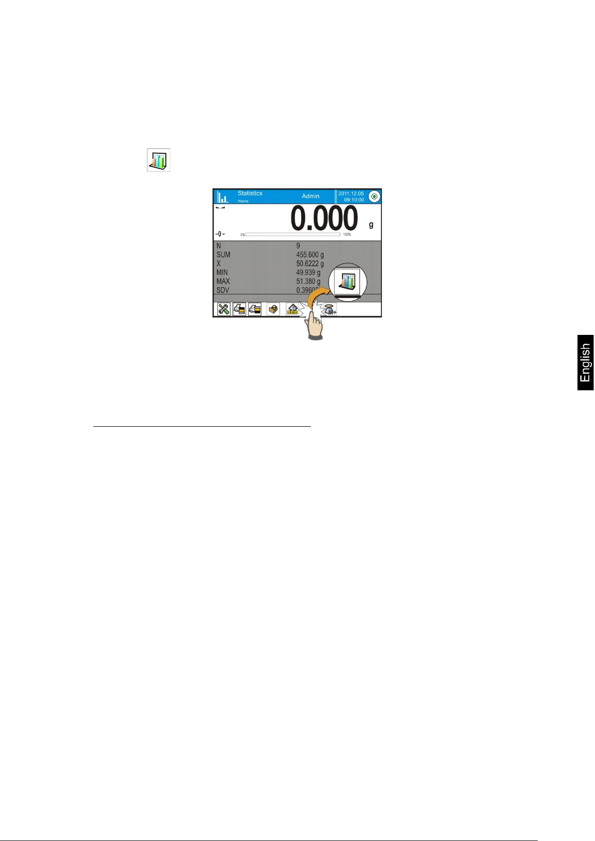
22.3. Parameters related to a series of measurements
Each series of measurements can be accompanied by the following options:
previewing results, printing report, deleting last measurement, deleting all
results in a statistics.
Procedure:
1. Press < Statistics> key
2. Displayed options: Result, Print, Delete last, Delete.
3. Select one of available option:
− Result, to preview statistics report,
− Print, to print report from statistics,
An example of report from statistics
-------------- Statistics --------------
N 9
SUM 455.600 g
X 50.6222 g
MIN 49.939 g
MAX 51.380 g
D 1.441 g
SDV 0.39605 g
RDV 0.78 %
----------------------------------------
− Delete last, if the last measurement has to be canceled,
− Delete, if all statistical data should be removed.
− Measurements chart – on selecting this option, the software
generates and displays a chart with distribution of measurements in
the coordinates mass/measurement for completed measurement
series.
AET_/PET_/ILT_NM-BA-e-1410 93
Page 94

Return to displaying the complete chart
Reducing the screen to the previous view
Return to displaying the previous window
Printing the chart on a connected printer PCL type
Saving the chart as a file in format *.bmp on an external data
Below there is an instance of the chart:
− Probability distribution chart – on selecting this option the
software generates and displays chart of probability distribution for
completed measurement series. Below there is an instance of the
chart. The bar chart demonstrates quantities of the same
measurement in a series.
The bottom bar contains the following soft keys (options):
storage device connected to terminal’s USB port.
94 AET_/PET_/ILT_NM-BA-e-1410
Page 95

23. PIPETTE CALIBRATION
Working mode < Pipette calibration> is dedicated to determining
measurement errors of volume in piston pipettes, in accordance with standard
ISO 8655 or according to user requirements.
In case of calibration carried out in accordance with standard ISO 8655, the
errors are auto matically selected to te sted volume, as specified in the standard
(see table of errors for standard ISO 8655).
Working mode enables:
• Calibrating pipettes with fixed or adjustable volume, single or multi-
channel;
• Preparing a database of pipettes including: pipette name, code, tested
volume and others;
• Calculating results on basis of:
Average volume of a pipette (channel)
Systematic error es (accu racy error)
Random error CV (repeatability error)
• Carrying out automated measuring procedures with consideration of
pipette’s type;
• Storing calibration results in a database (in a form of reports from
calibration process);
• Printing reports from pipette calibration process
• Exporting reports from tests
During volume testing procedure, the software determines accuracy and
repeatability errors f or tested volume.
In case of pipettes with adjustable volume, the softwar e enables dec laring up to
5 volume from total pipette’s range, that are checked during calibration process.
In order to ensure the highest accurac y of pipettes calibration process,
maintain the following ambient conditions at a workstation:
Ambient temperature of a pipette, tips and liquid shoul d be kept between
20°C - 25°C with change rate during testing within ± 0.5°C
Relative humidity 50 - 75%
and
Use distilled water for pipettes calibration processes
A pipette, tips and distilled water should be stabilized for temperature in
the weighing room. The reference norm advises that minimum
acclimatization time for above mentioned is 2 hours.
While calibrating process, balance user refers to the database of pipettes
including data on pipettes, its parameters, tested volume, and values of errors
determined for specific volumes.
Before carrying out calibration process, load database with data on pipettes and
calibration criteria.
AET_/PET_/ILT_NM-BA-e-1410 95
Page 96

Adding pipettes can only be carried out from the database level. Adding
procedure is described further in this user manual.
Working mode activating procedure
• while in the main windo w, press soft key located in the upper bar of the
display, which opens a submenu <Working modes> with selection of
available working m o des ,
• select < Pipettes calibration> mode, the software automatically
returns to the main window and displays pictogram in the upper bar,
On selecting the pipettes calibration mode, the display contains the
following quick access keys in the bottom bar:
1. Setup – access to balance’s menu
2. Pr int hea de r
3. Print footer
4. Select pipette
The grey coloured workspace contains the following data:
o Pipette
o Tested volume
o Average volume
o Systematic error
o Random error
o Status
96 AET_/PET_/ILT_NM-BA-e-1410
Page 97

23.1. Additional settings of pipettes calibration mode
The additional settings enable adjusting the working mode to user’s needs and
requirements. To access the setting follow below procedure:
Procedure:
1. Press grey coloured workspace,
2. The display indicate s menu of: Settings, Keys, Information, Pr intout
and Profile,
3. Press <Settings> key,
4. The display indicates functions related to calibration of pipettes.
Pipettes calibration is related to the following functions:
− Number of measurements; this opt ion enables determining number o f
measurements for tested volume of a pipette (valid for each tested
volume in case of a pipette with adjustable volume),
− Request serial number: YES/NO. For option <YES> before starting
calibration procedure, the software displays a window and on-screen
keyboard for inserting serial number of a pipette,
− Comply with ISO 8655: YES/NO. For option <YES>, for tested
volumes, during pipettes calibration process the software automatically
accepts error values as specified in standard ISO 8655 (if other error
values have been accepted for a pipette, then on selecting option
<Comply with ISO 8655> the error values are negle cted, and r eplaced by
those from ISO standard),
− Acquire data on ambient conditions from THB mod ule: YES/NO. For
option <YES> the software automatically, and in specified moment,
acquires and saves ambient conditions’ parameters fro m a connected T HB
module. If option < NO> is selected, befor e starting and after co mpleting
the pipettes calibra tion process operator should manually insert ambient
conditions parameters (i.e. temperature, humidity and pressure in the
weighing room) from external ambient conditions sensors.
− Result control, Tare mode, Automatic footer printout, Printout
mode, Printout, means of using these functions is given in point 10.8.
“Additional parameters on weighing process”.
23.2. Pipettes calibration – quick access keys
Each of working modes features a set of defaul t quick access keys which are
automatically displayed on mode activation. The set of keys can be modified
by selecting other quick access keys to the bottom bar of the display. Such
process requires appropriate operator’s access level.
AET_/PET_/ILT_NM-BA-e-1410 97
Page 98

23.3. Adding a pipette to the Database of Pipettes
Database of pipettes contains list of pipe ttes’ names and other da ta including
tested volume and err ors values for a specific volume. Whe n adding a pipette
to the database, first specify its name, and then add other data on a pipette.
The software operates intuitively, and commands a user to follow displayed
information.
Adding a pipette to the Database can be carried out in menu of the database.
Procedure:
• Enter submenu < Databases>, press < Pipettes> field
• Press < Add > soft key, should a new pipette be added
The software automatically adds a new entry to the database, and enters its
editing mode. Insert all parameters of a new formulation.
List of parameters defined for a pipette:
1. Name: press “Name” field, a window opens for inserting name of a
pipette;
2. Code: for inserting pipette’s code;
3. Model: for inserting model name of a pipette;
4. Tip: for inserting name of used tip;
5. Type of volume: ADJUSTABLE / FIXED;
6. Nominal volume: for specifying nominal volume of a pipette;
7. Mini mum volume: for specifying the minimum volu me of a pipette (in
case of a pipette with fixed volume, insert <0>);
8. Number of channels: for specifying number of pipette’s channels, in
case of a single channel pipette insert <1>;
9. Type: NONE/A/D1/D2. Pipette type is compatible with applicable
standard. Selecting pipette’s type is mandatory if calibration process
complies with the requirements of standard ISO 8655, as values of
errors differ in each type of a pipette. Therefore, if the software is to
accept adequate error values it is necessary to determine type of a
pipette;
10. Tested volumes: if pressed, a window is opened with a list of
calibrated volumes (in case of a new pipette, the list is empty), add
volume to be tested, and define error value for each tes ted volume:
• Press < Add > soft key
• A window with on-screen numeric keyboard is displayed,
• Insert value of tested volume in [µl] and accept by pressing <
> key,
• A new record is automatically added to the list with recommended
error values,
• In order to change error values press a field with added volume
of a pipette,
98 AET_/PET_/ILT_NM-BA-e-1410
Page 99

− Working mode
− Temperature
each field is editable and enables inserting user values,
Caution:
While in calibration process, the order of tested volumes corresponds to
the order in which they are entered.
• On setting correct values return to the main window.
23.4. Printouts
Option Printouts enables setting the content of a standard printout as well
as the non-standard printout.
Standard printout
comprises four internal sections featuring different variables. For each
variable set optio n YES to include it in a s tandard pr intout. If option NO is
selected, then the variable is disabled, i.e. it is not printed.
Settings for header printout, weighing printout, and footer printout are
specified in point. 15.5; below description refers to setting a printout
template for report from pipette calibration.
Content of each of reports:
− User
− Client
− Pipette
− Serial no.
− No. of channels
− Channel no.
− Number of measurements
− Oper atio n with ISO 8 6 55
− Start date
− End date
− Water temperature
AET_/PET_/ILT_NM-BA-e-1410 99
Page 100

−
− Humidity
− Non-standard printout
23.5. Working mode activating procedure
Carrying out pipettes calibration process requires installing an adapter for
pipettes calibration. The adapter does not come standard with the balance.
The adapter for pip ettes calibration is a simple supplementary device dedicated
for calibration and che cking of p iston pipette s. The adapter has be en des igned to
minimize evaporation occurring in liquid handling procedures. It consists of a
minimized weighing cha mber installe d inside the w eighing chambe r of a balance.
The adapter features an evaporation ring and a dedicated weighing pan for
central locating of the measuring vessel.
Application of the adapter for pipettes calibration prevents from liquid
evaporation during calibration process. Small dimensions of the adapter,
combined with the evapora tion ring enable maintain ing high humidi ty rate inside
the weighing chamber and the measuring vessel, thus stopping liquid
evaporation process.
Carried out research proved that the adapter for pipettes calibration eliminates
or considerably reduces liquid evaporation process, which is essential for correct
gravimetric calibration of piston pipettes.
Selecting an appropriate adapter and balance mostly depends on type of
calibrated pipettes.
Before starting pipettes calibration process, assembly the adapter inside
balance’s weighing chamber, and insert data on pipettes to be calibrated,
including complete pipette characteristi cs and values of er rors (see: Database of
Pipettes).
The following step is setting process’s main option:
• Number of measurements
• Request batch number (YES/NO)
• Operation with ISO 8655 (YES/NO)
• Acquire ambient conditions from THB module (YES/NO)
Caution:
Description of options and settings are given in point 24.1 of this user manual.
After setting the above options, go to pipettes calibration process.
− Pressure
− Z coefficient
− Measurements and statistics
− Statistics
− Status
− Empty line
− Dashes
− Signature
100 AET_/PET_/ILT_NM-BA-e-1410
 Loading...