

Page 1

KERN & Sohn GmbH
Ziegelei 1
D-72336 Balingen-Frommern
E-Mail: info@kern-sohn.com
Tel: 0049-[0]7433- 9933-0
Fax: 0049-[0]7433-9933-149
Internet: www.kern-sohn.com
GB
Service Manual
Electronic Counting Balance
Page 2
KERN CPB
Software rev.: 3.02 & above
Version 2.1 11/2007
Page 2

CPB-SH-e-0721 2
CONTENTS
1.0 INTRODUCTION ..................................................................................................3
2.0 SPECIFICATIONS................................................................................................4
2.0 TROUBLESHOOTING..........................................................................................5
3.0 INSTALLATION ....................................................................................................6
3.1 GENERAL
INSTALLATION...............................................................................6
3.2 PREPARATION FOR USE................................................................................6
4.0 SERVICE PARAMETERS.....................................................................................8
4.1 USING “0000” TO ENTER THE CALIBRATION PARAMETER..........................8
4.1.1 F1 - CALIBRATION.........................................................................................9
4.1.2 F2 - PIN FOR CALIBRATION.........................................................................9
4.2 USING
“2006” TO ENTER THE SERVICE PARAMETERS .............................11
4.2.1 F1 - CALIBRATION....................................................................................... 12
4.2.1 F1 - CALIBRATION....................................................................................... 12
4.2.2 F2 - RESOLUTION.......................................................................................12
4.2.3 F3 - CAPACITY ............................................................................................12
4.2.4 F4 - INITIAL ZERO RANGE..........................................................................13
4.2.5 F5 - RE-ZERO RANGE ................................................................................13
4.2.6 F6 - SUCCESSIVE TARE.............................................................................13
4,2.7 F7 - A/D COUNT...........................................................................................14
4.2.8 F8 - ZERO....................................................................................................14
4.2.9 F9 - PIN........................................................................................................14
4.2.10 F10 - LVD MODE..........................................................................................15
4.3 WEIGHING UNITS [KG / G] ................................................................................15
5.0 WIRING DIAGRAM.............................................................................................16
6.0 MECHANICAL ASSEMBLY................................................................................17
7.0 FRONT DISPLAY SCHEMATIC .........................................................................18
7.1 FRONT DISPLAY ASSEMBLY........................................................................19
8.0 MAIN PCB SCHEMATIC.....................................................................................20
8.1 MAIN
PCB ASSEMBLY..................................................................................21
Page 3

1.0 INTRODUCTION
• The CPB series of scales provide an accurate, fast and versatile counting
and check-weighing scales.
• CPB scales are kilogram only scales.
EC type approved scales are limited to lower resolution operation,
however the counting abilities still use the same internal resolution.
• They all have stainless steel weighing platforms on an ABS base
assembly.
• All scales available with RS-232 interface and real time clock (RTC).
• All scales have sealed keypad with colour coded membrane switches and
there are three large, easy to read liquid crystal type displays (LCD). The
LCD’s are supplied with a backlight.
• The scales include automatic zero tracking, audible alarm for pre-set
weights, automatic tare, pre-set tare, an accumulation facility that allows
the count to be stored and recalled as an accumulated total and an bidirectional RS-232 interface for communicating with a PC or printer.
CPB-SH-e-0721 3
Page 4
CPB-SH-e-0721 4
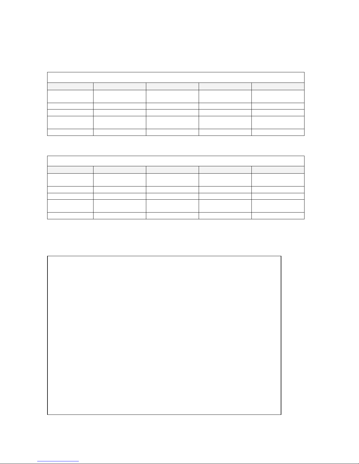
2.0 SPECIFICATIONS
Approved Series
CPB-M SERIES
Model # CPB 3K1M CPB 6K2M CPB 15K5M CPB 30K10M
Maximum
Capacity
3000 g 6000 g 15 kg 30 kg
Readability 1 g 2 g 0.005 kg (5g) 0.01 kg (10g)
Tare Range -3000 g -6000 g -15 kg -30 kg
Repeatability
(Std Dev)
1 g 2 g 0.005 kg (5g) 0.01 kg (10g)
Linearity ± 2 g 4 g 0.01 kg (10g) 0.02 kg (20g)
Non Approved Series
CPB SERIES
Model # CPB 3K0.1 CPB 6K0.2 CPB 15K0.5 CPB 30K1
Maximum
Capacity
3000 g 6000 g 15 kg 30 kg
Readability 0.1 g 0.2 g 0.5g 1g
Tare Range -3000 g -6000 g -15 kg -30 kg
Repeatability
(Std Dev)
0.1 g 0.2 g 0.5g 1g
Linearity ± 0.4 g 0.8 g 1.5 g 3 g
Common Specifications
Interface RS-232 bi-directional interface
Stabilisation Time 2 Seconds typical
Operating
Temperature
0°C - 40°C
32°F - 104°F
Power supply 230 VAC 50/60 Hz.
120 VAC available.
Battery Internal rechargeable battery
(~50 hours operation)
Calibration External
Not available on EC approved units (locked)
Display 3 x 6 digits LCD digital displays
Balance Housing ABS Plastic, Stainless Steel platform
Pan Size 225 x 275mm
8.9” x 10.8”
Overall Dimensions
(wxdxh)
315 x 355 x 110mm
12.4” x 14” x 4.3”
Net Weight 4.1 kg / 9 lb
Applications Counting Scales
Functions Parts counting, weighing, accumulating memory,
pre-set count with alarm
Interface RS-232 bi-directional interface
Date/Time Real Time Clock (RTC),
To print date and time information.
(Dates in year/month/day, day/month/year or
month/day/year formats Battery backed)
Page 5

CPB-SH-e-0721 5
2.0 TROUBLESHOOTING
1. Unit does not
turn on
Check whether the scale is plugged into the power supply properly.
Check the operation of the charging circuit.
Check whether the battery is charged- LED should turn to green
from red.
Check the adapter output.
.
2. The scale
weighs but is
unstable
Air drafts or vibration or unstable table.
Pan rubbing against case or not installed correctly.
Scale not installed properly.
Improper connections on ADC circuit.
3. Scale shows
wrong weight
Scale not installed correctly.
Check the Calibration.
To check whether a part of product weighed is trapped between
the pan and the scale.
Incorrect adjustment of the mechanical stops.
4.
An error “
E4”
displays on
the screen
Load cell damage.
Scale not installed properly.
Incorrect adjustment of the mechanical stops.
Factory calibration has been tampered with- check the ADC counts
and re-calibrate.
Page 6

CPB-SH-e-0721 6
3.0 INSTALLATION
3.1 GENERAL INSTALLATION
The scales should not be placed in a location that will reduce the accuracy.
Avoid extremes of temperature. Do not place in direct sunlight or near air conditioning
vents.
Avoid unsuitable tables. The table or floor must be rigid and not vibrate.
Avoid unstable power sources. Do not use near large users of electricity such as
welding equipment or large motors.
Do not place near vibrating machinery.
Avoid high humidity that might cause condensation. Avoid direct contact with water. Do
not spray or immerse the scales in water.
Avoid air movement such as from fans or opening doors. Do not place near open
windows or air-conditioning vents.
Keep the scales clean. Do not stack material on the scales when they are not in use.
3.2 PREPARATION FOR USE
The scales come with a stainless steel platform, packed separately.
Place the platform in the receptacles on the top cover.
Do not press with excessive force as that could damage the load cell inside.
Level the scale by adjusting the four feet. The scale should be adjusted such that the
bubble in the spirit level is in the centre of the level and the scale is supported by all four
feet.
Turn the power ON using the switch located on the right side of the base.
Page 7

CPB-SH-e-0721 7
The unit will display the software revision number in the Weight window and count
down to zero while performing a self-test.
When ready all three displays will show zero.
Refer to the CPB user manual for detailed operating instructions.
Page 8

4.0 SERVICE PARAMETERS
• Place your balance upside down
• Remove seal
• For verified balances, the jumper is on a pin
• For adjustment the jumper must be set on both pins
Position jumper for adjustment
CPB-SH-e-0721 8
Position
of seal
Bottom of the balance
4.1 USING “0000” TO ENTER THE CALIBRATION PARAMETER
After the jumper has been placed in the position shown, apply power to the scale.
The display will ask for a code number, “Pn” on the Weight Display.
Enter the number “0000” then press [Tare]. The display will show “F1” “CAL”. To enter
the calibration press [Tare] and to skip the calibration, press . “F2” “Pin” will be
displayed.
NOTE: If the PIN number has been changed by other users, the correct Pin number will
be required in place of 0000.
Page 9

4.1.1 F1 - CALIBRATION
To enter the calibration parameter, press the [Tare] key when “F1” “CAL” is displayed.
The Weight display will instruct you to remove any weight from the scale, “UnloAd”
Press the [Tare] key. The displays will ask you to place the calibration weight on the
scale: “LoAd” “06” “kilo6”
NOTE: The CPB-M series should be calibrated with the full capacity weight. That is for
CPB 6K2M, use 6 kg as calibration weight.
Add the suggested calibration weight as displayed or press the key to clear the
value and enter another value of weight. To add this value to the platform, wait for
stability then press the [Tare] key.
The display will show “SPAn” “PASS” if the calibration is OK. Or it will show “SPAn” “FAIL”
if calibration could not be completed correctly.
The display will show “JP On”. Remove the calibration mass.
Remove the jumper and the scale will run a self-test and return to normal operation.
4.1.2 F2 - PIN FOR CALIBRATION
This parameter allows changing of the PIN number to gain access to calibration.
To set the PIN, press the [Tare] key when “F2” “Pin” is displayed.
The display will show “Pin 1”
Enter the new Pin number. Press the [Tare] key to accept.
The display will show “Pin 2”
Enter the new Pin number a second time. Press the [Tare] key to accept.
CPB-SH-e-0721 9
Page 10

CPB-SH-e-0721 10
The display will show “dOnE” if the number was accepted or “FAiL” if the numbers were
not the same.
The scale returns to the parameter menu displaying “F2” “Pin”.
Turn the power off, remove the jumper and restart the scale. The new settings are now
in operation.
Page 11

4.2 USING “2006” TO ENTER THE SERVICE PARAMETERS
After the jumper has been placed in the position shown, apply power to the scale.
The display will ask for a code number, “Pn” on the Weight Display.
Enter the number 2006 when “Pn” is displayed and then press [Tare].
The displays will show the first parameter “F1” “CAL”. To scroll through other
parameters press the key.
Press the [Tare] key to enter a parameter.
To exit a parameter, press the key.
The Weight Display window will show the parameter number and the Piece Weight
window will show the word describing the function.
When a parameter is entered by pressing the [Tare] key, the displays will guide you
through the parameter selected and the options available.
The parameters available are:
F1 CAL To enter the Calibration
F2 rES Resolution selection, not valid for CPB-M units
F3 CAPA Select Capacity
F4 init ZEro Initial Zero Range
F5 rE ZEro Re-Zero Range
F6 SCSivE tArE Successive Tare Enable
F7 Ad Count Display the A/D counts
F8 ZEro Set zero method.
F9 Pin Set new PIN number
F10 LVd ModE Set low voltage detect mode
CPB-SH-e-0721 11
Page 12

4.2.1 F1 - CALIBRATION
To enter the calibration parameter, press the [Tare] key when “F1” is displayed.
The display will instruct you to remove any weight from the scale by displaying “UnloAd”
Press the [Tare] key.
The display will tell you to add the calibration weight to the scale: “LoAd 1” “ 05”
“kiLo5”
Add the weight shown or press the key to clear the value and enter another value
of weight. Wait for the stability indicator and then press the [Tare] key.
The display will show “SPAn” “PASS” if the calibration is OK or it will show “SPAn” “FAIL”
if calibration could not be completed correctly.
The display will show “JP On”. Remove the calibration weight.
Remove the jumper and the scale will run a self-test and return to normal operation.
4.2.2 F2 - RESOLUTION
This function is not active on the CPB-M series.
4.2.3 F3 - CAPACITY
To enter this parameter, press the [Tare] key when “F3” is shown.
The display will show the current capacity in 3, 6, 15 or 30 kilograms.
Press the key to change the value.
Press [Tare] to accept the displayed value.
NOTE: The scale must be originally built for the capacity selected. The 3kg unit
uses the 5kg load cells, 6kg unit uses 10kg load cells, the 15kg unit uses 20kg load
cells and the 30kg unit uses 35kg load cells.
CPB-SH-e-0721 12
Page 13

4.2.4 F4 - INITIAL ZERO RANGE
To enter this parameter, press the [Tare] key when “F4” is shown.
The display will show the current initial zero range.
Press the key to change the value and press [Tare] to accept the value.
NOTE: Only 10% is allowed for the CPB-M scales.
4.2.5 F5 - RE-ZERO RANGE
To enter this parameter, press the [Tare] key when “F5” is shown.
The display will show the current re-zero range.
Press the key to change the value and press [Tare] to accept the value.
NOTE: Only 2% is allowed for the CPB-M scales.
4.2.6 F6 - SUCCESSIVE TARE
To enter this parameter, press the [Tare] key when “F6” is shown.
The display will show if the successive tare is on or off.
Press the key to change the value.
Press [Tare] to accept the displayed value.
NOTE: Either option is allowed for the CPB-M scales.
CPB-SH-e-0721 13
Page 14

4,2.7 F7 - A/D COUNT
To enter this parameter, press the [Tare] key when “F7” is shown.
This parameter allows you to view the A/D counts from the internal A/D converter. This
can be an aid to service.
Press the [Tare] key to return to the PARAMETER menu.
Press the key to return to normal weighing.
Typical value at zero is 30,000-90,000 (approx.)
Typical value at full capacity is 500,000 (approx.)
4.2.8 F8 - ZERO
The scale can be selected to use a normal method to determine zero, “Mode 1” or an
alternative method “Mode 2”. For all CPB-M scales set this option to “Mode 1”.
To enter this parameter, press the [Tare] key when “F8” is shown.
The display will show the selected zero mode.
Press the
key to change the value.
Press [Tare] to accept “
Mode 1”.
4.2.9 F9 - PIN
To change the user Pin number to gain access to the Service Parameters.
To enter this parameter, press the [Tare] key when “F9” is shown.
The display will show “Pin 1”
Enter the new Pin number. Press the [Tare] key to accept.
CPB-SH-e-0721 14
Page 15

The display will show “Pin 2”
Enter the new Pin number a second time. Press the [Tare] key to accept.
The display will show “dOnE” if the number was accepted or “FAiL” if the numbers were
not the same.
The scale returns to the parameter menu.
4.2.10 F10 - LVD MODE
It stands for Low Voltage Detect mode. The Low voltage detection can be enabled or
disabled.
To enter this parameter, press the [Tare] key when “F10” is shown.
The display will show if the LVD is “on” or “oFF”.
Press the key to change the value.
Press [Tare] to accept “on”.
NOTE: Only “
LVD” “on” is allowed for the CPB-M scales.
Turn the power off, remove the jumper and restart the scale. The new settings are now
in operation.
4.3 WEIGHING UNITS [kg / g]
The current software of CPB was standardised to weigh in [kg].
There is a function to enable the scale to weigh in [g].
The scale has to be opened and a connecting jumper has to be fitted to “JTAG” pins 1
and 2 on the main board to enable the [g] display.
NOTE: The selection between both units is not possible for the CPB-M scales.
CPB-SH-e-0721 15
Page 16

5.0 WIRING DIAGRAM
CPB-SH-e-0721 16
Page 17

6.0 MECHANICAL ASSEMBLY
CPB-SH-e-0721 17
Page 18

7.0 FRONT DISPLAY SCHEMATIC
CPB-SH-e-0721 18
Page 19

7.1 FRONT DISPLAY ASSEMBLY
CPB-SH-e-0721 19
Page 20

8.0 MAIN PCB SCHEMATIC
CPB-SH-e-0721 20
Page 21

8.1 MAIN PCB ASSEMBLY
CPB-SH-e-0721 21
Page 22

Discussion with the manufacturer
In discussions with the manufacturer’s works the following information should be
provided:
• Balance type e.g. CPB 15K5M
• Series number e.g. WP0702716 (Label on the left side of the balance)
• Program number e.g. U3.06A (appears on the display when switching on
the balance)
• As precise a description of the defect as possible
• Weighing results
KERN & Sohn GmbH
Ziegelei 1
D-72336 Balingen-Frommern
Tel.: 0049-7433-9933-0
Fax: 0049-7433-9933-149
e-mail: info@kern-sohn.com
URL: www.kern-sohn.com
 Loading...