

Page 1
www.mercury-security.com
2355 MIRA MAR AVE. LONG BEACH, CA 90815-1755, (562)986-9105 FAX (562) 986-9205
This device complies with part 15 of the FCC Rules.
Operation is subject to the following two conditions: (1) This
device may not cause harmful interference, and (2) this
device must accept any interference received, including
interference that may cause undesired operation.
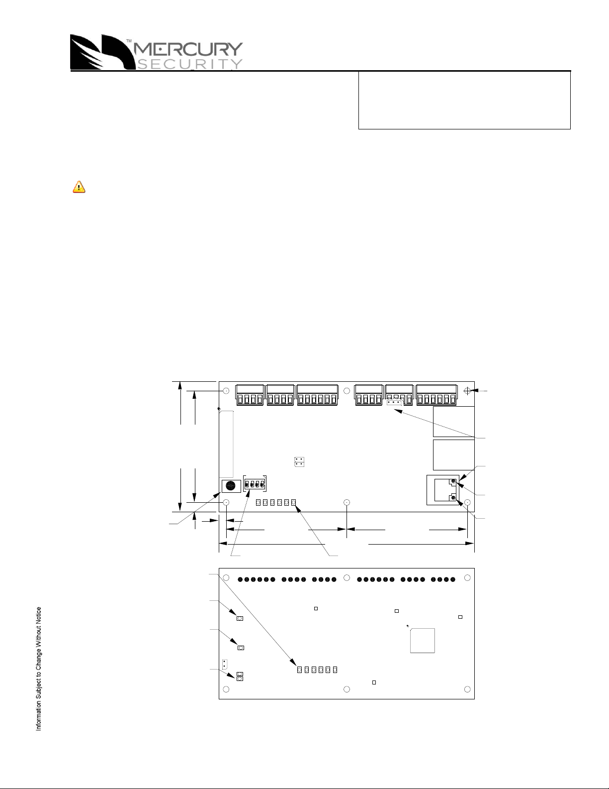
MR51e Reader Interface
234 1
S1
S2
123456
ON
J3J7
K1
K2
12V
J5
PoE
J6
TB1 TB2 TB3 TB4 TB5 TB6
11 1 1 1 1
IN1 IN2 IN3 IN4 VO LED BZR CLK DATGND VO GNDDATCLKBZRLED GNDVIN NO NC2-CNONC1-C
J2
0.2 [5.08] 2.35 [59.69]
0.15 [3.81]
2.55 [64.77] 2.55 [64.77]
5.4 [137.16]
STATUS LEDs
2.75 [69.85]
DIP SWITCH
RESET SWITCH
PoE/12Vdc
POWER SELECTOR
JUMPER
ETHERNET RJ45
CONNECTOR
ACTIVITY
(YELLOW)
LINK
(GRREN)
Ø0.125 [Ø3.18]
4 PLACES
1 2 3 4 5 6
VO
VO
IN2
IN1
IN3
IN4
LED
BZR
CLK
DAT
GND
LED
BZR
CLK
DAT
NC
GNDGND
VIN
NO
RLY 1
NO
RLY 2
NC
C
C
TB6
TB5
TB4
TB3
TB2
TB1
J1
6V
5V
3.3V
LNK
ACT
(K1)
(K2)
J4
D24
D19
ETHERNET
STATUS
LEDs
RELAY K1
LED
RELAY K2
LED
STATUS LEDs
SOLDER SIDE
Installation and Specifications
1. General:
The MR51e reader interface provides a network connected, single door with paired reader, PoE based
solution to the OEM integrator for interfacing TTL/Wiegand/RS-485 type readers to door hardware. The
on-board twisted pair Ethernet jack with PoE support enables easy installation.
Note: For UL, the Power Sourcing Equipment (PSE) such as a PoE enabled network switch and/or PoE
power injectors must be UL Listed under UL294.
One physical barrier can be controlled with the MR51e, using single or paired readers. The first reader
port can accommodate a read head that utilizes Wiegand, magnetic stripe, or 2-wire RS-485 electrical
signaling standards, one or two wire LED controls, and buzzer control (one wire LED mode only).
The second reader port can accommodate a read head that utilizes Wiegand or magnetic stripe
signaling, one or two wire LED controls, and buzzer control (one wire LED mode only). Two Form-C
relay outputs may be used for door strike control or alarm signaling. The relay contacts are rated at 5 A
@ 30 Vac/dc, dry contact configuration. Four inputs are provided for monitoring the door contacts, exit
push buttons, and alarm contacts. The MR51e requires power from PoE or local 12 Vdc. The MR51e
may be mounted in a 3-gang switch box; a mounting plate is supplied with the unit. The MR51e may be
mounted in an enclosure; the supplied mounting plate has mounting holes that match the MR50
mounting footprint.
2. MR51e Hardware:
Mercury Security © 2013 MR51e DOC 10107-0035 REV 1.05 Page 1
Page 2

MR-51E CONNECTIONS
TB1-1
IN1
Input 1
TB1-2
IN1
TB1-3
IN2
Input 2
TB1-4
IN2 TB2-1
IN3
Input 3
TB2-2
IN3
TB2-3
IN4
Input 4
TB2-4
IN4 TB3-1
VO
Reader 1 Power Output – 12 VDC
TB3-2
LED
Reader 1 LED Output
TB3-3
BZR
Reader 1 Buzzer Output
TB3-4
CLK
Reader 1 CLK/Data 1/TR+
TB3-5
DAT
Reader 1 DAT/Data 0/TR-
TB3-6
GND
Reader 1 Ground
TB4-1
LED
Reader 2 LED Output
TB4-2
BZR
Reader 2 Buzzer Output
TB4-3
CLK
Reader 2 CLK/Data 1 Input
TB4-4
DAT
Reader 2 DAT/Data 0 Input
TB5-1
VO
Auxiliary Power Output – 12 Vdc
TB5-2
GND
Auxiliary Power Output Ground
TB5-3
VIN
Input Power – 12 Vdc (from local power supply)
TB5-4
GND
Input Power Ground
TB6-1
NO
Relay K1 – Normally Open Contact
TB6-2
1-C
Relay K1 – Common Contact
TB6-3
NC
Relay K1 – Normally Closed Contact
TB6-4
NO
Relay K2 – Normally Open Contact
TB6-5
2-C
Relay K2 – Common Contact
TB6-6
NC
Relay K2 – Normally Closed Contact
JUMPER
SET AT
DESCRIPTION
J1
N/A
Factory Use Only
J2
N/A
Factory Use Only
J3
N/A
Factory Use Only
J4
N/A
Factory Use Only
J5
PoE
MR-51E powered from the Ethernet connection
12V
MR-51E powered from an external 12 Vdc power
source connected to TB5-3 (VIN), TB5-4 (GND)
J6
N/A
Ethernet Connection with POE support
J7
N/A
Factory Use Only
MR51e Terminal Blocks and Jumpers/Jacks:
Jumpers:
Mercury Security © 2013 MR51e DOC 10107-0035 REV 1.05 Page 2
Page 3

4 3 2 1 Addressing Mode Meaning
OFF
OFF
OFF
OFF
MSC-Specific DHCP (original method)
OFF
OFF
OFF
ON
Public DHCP
OFF
OFF
ON
OFF
Static IP
OFF
OFF
ON
ON
Programming Mode for Static IP Address Assignment
ON
ON
ON
ON
MSC-Specific DHCP (original method)
MR-10/20 READER
ADDRESS 0
MR-DT
RS-485 MODE
9600 BAUD
TB3
TB3
FIRST READER PORT
DATA1/DATA0 OR CLOCK/DATA
FIRST READER PORT
2-WIRE RS-485
WHT (3)
BLK (6)
GRN (2)
ORG (5)
BRN (4)
RED (1)
CLK/D1
GND
DAT/D0
LED
BZR
VO
12Vdc (RED) (1)
TR+ (BLUE) (3)
GROUND (BLACK) (2)
TR- (GRAY) (4)
DAT/D0
CLK/D1
GND
VO
1
1
TB4 TB5
SECOND READER PORT
DATA1/DATA0 OR CLOCK/DATA
WHT (3)
RED (1)
GRN (2)
ORG (5)
BRN (4)
BLK (6)
CLK/D1
GND
VO
DAT/D0
LED
BZR
1 1
MR-10/20 READER
3. DIP Switches:
The addressing mode used is determined by the DIP switch setting on the MR51e:
Notes:
Public DHCP and Static IP Addressing Modes are available with MR51e firmware
revisions 1_4_2 and later
All other DIP switch settings are reserved for future use
Press S2 to reset board after DIP switch is changed for new address mode
4. Input Power:
The MR51e is powered by one of two ways (jumper selected):
Power is supplied via the Ethernet connection using PoE, fully compliant to IEEE 802.3af
Or local 12 Vdc power supply, TB5-3 (VIN), TB5-4 (GND).
5. Communication Wiring:
Communication between the EP controller and the MR51e is Ethernet. (10Base-T/100Base-TX)
6. Reader Wiring:
The first reader port supports Wiegand, magnetic stripe, and 2-wire RS-485 electrical interfaces. The
second reader port supports Wiegand and magnetic stripe electrical interfaces. Power to the first reader
is 12 Vdc and is current limited to 150 mA. The second reader may be powered from the auxiliary power
output on TB5-1 and TB5-2. Readers that require different voltage or have high current requirements
should be powered separately. Refer to the reader manufacture specifications for cabling requirements.
In the 2-wire LED mode, the Buzzer output is used to drive the second LED. Reader port configuration
is set via the host software.
When powering any remote device(s) by the MR51e, care must be taken not to exceed the maximum
current available. Cable gauge must also be evaluated. See specifications section for details.
Mercury Security © 2013 MR51e DOC 10107-0035 REV 1.05 Page 3
Page 4

1K,1%
1K,1%
1K,1%
1K,1%
Standard Supervised Circuit,
Normally Closed Contact
Standard Supervised Circuit,
Normally Open Contact
Unsupervised Circuit,
Normally Open Contact
Unsupervised Circuit,
Normally Closed Contact
TB2
IN4
IN2
IN3
1
IN1
TB1
1
}
7. Input Circuit Wiring:
Typically, these inputs are used to monitor door position, request to exit, or alarm contacts. Input circuits
can be configured as unsupervised or supervised. When unsupervised, reporting consists of only the
open or closed states.
When configured as supervised, the input circuit will report not only open and closed, but also open
circuit, shorted, grounded*, and foreign voltage*. A supervised input circuit requires two resistors be
added to the circuit to facilitate proper reporting. The standard supervised circuit requires 1K Ohm, 1%
resistors and should be located as close to the sensor as possible. Custom end of line (EOL)
resistances may be configured via the host software.
* Grounded and foreign voltage states are not a requirement of UL 294 and therefore not verified by UL.
The input circuit wiring configurations shown are supported but may not be typical:
8. Relay Circuit Wiring:
Two Form-C contact relays are provided for controlling door lock mechanisms or alarm signaling. The
relay contacts are rated at 5 A @ 30 Vac/dc, dry contact configuration. Each relay has a Common pole
(C), a Normally Open pole (NO) and a Normally Closed pole (NC). When you are controlling the delivery
of power to the door strike, the Normally Open and Common poles are used. When you are
momentarily removing power to unlock the door, as with a mag lock, the Normally Closed and Common
poles are used. Check with local building codes for proper egress door installation.
Door lock mechanisms can generate feedback to the relay circuit that can cause damage and premature
failure of the relay. For this reason, it is recommended that either a diode or MOV (metal oxide varistor)
be used to protect the relay. Wire should be of sufficient gauge to avoid voltage loss.
Mercury Security © 2013 MR51e DOC 10107-0035 REV 1.05 Page 4
Page 5

Diode Selection:
Diode current rating: 1x strike count
Diode breakdown voltage: 4x strike voltage
For 12 Vdc or 24 Vdc strike, diode 1N4002
(100V/1A) typical.
MOV Selection:
Clamp voltage: 1.5x Vac RMS.
For 24 Vac strike, Panasonic ERZ-C07DK470
typical
LED
DESCRIPTION
1
Off-line: 0.2 second ON, 0.8 second OFF
Waiting for application firmware to be downloaded: .1 sec ON, .1 sec OFF
2
Waiting for IP address: 0.5 second ON, 0.5 second OFF
LED
DESCRIPTION
On-line, encryption disabled = 0.8 second ON, 0.2 second OFF
1
On-line, encryption enabled = four pulses; 0.1 second ON, 0.1 second OFF per second
Off-line: 0.2 second ON, 0.8 second OFF (static addressing mode only)
Waiting for application firmware to be downloaded: .1 sec ON, .1 sec OFF
2
Flashes when there is host communication (approximately every 5 seconds)
3
Flashes when data is received from either reader/downstream devices
4
Input IN1 Status: OFF = Inactive, ON = Active, Flashing = Trouble. See note 1
5
Input IN2 Status: OFF = Inactive, ON = Active, Flashing = Trouble. See note 1
6
Input IN3 Status: OFF = Inactive, ON = Active, Flashing = Trouble. See note 1
YEL
Ethernet speed: OFF = 10 Mb/S, ON = 100 Mb/S
GRN
OFF = No Link, ON = Good Link, Flashing = Ethernet Activity
TB5
2-C
NC
NC
NO
1
NO
1-C
TB6
1
NO
1-C
NC
NC
NO
2-C
Relay Circuit Wiring (continued):
It is possible for the MR51e to provide power for a 12 Vdc door strike providing the maximum current is
not exceeded, see specification section.
9. Status LEDs:
At power up, LEDs 2 through 6 are turned ON then OFF in sequence.
After the above sequence has completed successfully, the MR51e goes to the “Waiting for IP Address”
mode, when in the MSC-Specific DHCP or Public DHCP addressing modes:
Waiting for IP Address mode:
The following table describes the LED’s in the Normal Running mode. If communication is lost, the
MR51e reverts back to the “Waiting for IP Address” mode, when in the MSC-Specific DHCP or Public
DHCP addressing modes:
Normal Running mode:
Note 1: If this input is defined, every three seconds the LED is pulsed to its opposite state for 0.1
second, otherwise, the LED is off.
Mercury Security © 2013 MR51e DOC 10107-0035 REV 1.05 Page 5
Page 6

10. Specifications:
The interface is for use in low voltage, Class 2 circuits only.
Power Input: PoE Power Input 12.95 W, compliant to IEEE 802.3af
– OR –
12 Vdc 10%, 900 mA maximum
Power Output: 12 Vdc @ 650 mA maximum (reader and AUX outputs combined)
Reader (TB3) 12 Vdc (10.3 through 12.6) @ 150 mA maximum
AUX (TB5) 12 Vdc (10.7 through 13.0) @ 650 mA maximum
Note: For UL, the Power Sourcing Equipment (PSE) such as a PoE enabled network switch and/or PoE
power injectors must be UL Listed under UL294.
Output: 2 outputs, Form-C contacts rated at 5 A @ 30 Vac/dc
Inputs: 4 unsupervised/supervised, End of Line resistors, 1k/2k ohm, 1% 1/4 watt
standard
Reader Interface:
Reader Power: See Power Output above.
Reader LED Output: TTL compatible, high > 3 V, low < 0.5 V, 5 mA source/sink maximum
Buzzer Output: Open collector, 5 Vdc open circuit maximum, 10 mA sink maximum
Reader Data Inputs: TTL compatible inputs or 2-wire RS-485
Cable Requirements:
Communication: Ethernet, Category 5, minimum
Power: 18 AWG, 1 twisted pair
Alarm Inputs: 1 twisted pair per input, 30 ohm maximum
Reader data (TTL): 18 AWG, 6 conductors, 500 foot (152 m) maximum
Reader data (RS-485): 24 AWG, 120 ohm impedance, twisted pair, shield, with drain wire, 2000 foot
(609.6 m) maximum
Mechanical:
Dimension: 5.5" (140 mm) W x 2.75" (70 mm) L x 0.96" (24 mm) H without bracket
5.5" (140 mm) W x 3.63" (92 mm) L x 1.33" (34 mm) H with bracket
Weight: 4.2 oz. (120 g) without bracket
5.3 oz. (150 g) with bracket
Environment:
Temperature: -55 to +85 C, storage
0 to +70 C, operating
Humidity: 10 to 95% RHNC
Mercury Security © 2013 MR51e DOC 10107-0035 REV 1.05 Page 6
Page 7

FIELD WIRING
MR51e WITH INCLUDED
MOUNTING PLATE
TO ETHERNET
NETWORK
OPTIONAL 3-GANG
JUNCTION BOX
OPTIONAL BLANK
COVER W/SCREWS
OPTIONAL MAGNETIC
TAMPER SWITCH
3.85 [97.8]
2.35 [59.7]
5.50 [139.7]
3.63 [92.1]
3.30 [83.8]
3.63 [92.1]
Ø0.16 [Ø4.0]
MR50 MGT HOLES
4PL
Ø0.16 [Ø4.0]
3-GANG MGT HOLES
4PL
11. Additional Mounting Information:
Sources for the optional items shown below:
3-gang stainless steel blank cover: Leviton part number 84033-40.
Available from Graybar, part number 88158404
Magnetic switch set: G.R.I. part number: 505
Side View:
Mounting Plate Dimensions:
Mercury Security © 2013 MR51e DOC 10107-0035 REV 1.05 Page 7
Page 8

Warranty
Mercury Security warrants the product is free from defects in material and workmanship under normal use
and service with proper maintenance for one year from the date of factory shipment. Mercury Security
assumes no responsibility for products damaged by improper handling or installation. This warranty is
limited to the repair or replacement of the defective unit.
There are no expressed warranties other than set forth herein. Mercury Security does not make, nor
intends, nor does it authorize any agent or representative to make any other warranties, or implied
warranties, and expressly excludes and disclaims all implied warranties of merchantability or fitness for a
particular purpose.
All returns must be accompanied by a Return Material Authorization (RMA) number obtained from
customer service, and prepaid postage and insurance.
Liability
The Interface should only be used to control exits from areas where an alternative method for exit is
available. This product is not intended for, nor is rated for operation in life-critical control applications.
Mercury Security is not liable under any circumstances for loss or damage caused by or partially caused
by the misapplication or malfunction of the product. Mercury Security’s liability does not extend beyond
the purchase price of the product.
Mercury Security © 2013 MR51e DOC 10107-0035 REV 1.05 Page 8
 Loading...