

Page 1
www.mercury-security.com
2355 MIRA MAR AVE. LONG BEACH, CA 90815-1755, (562)986-9105 FAX (562) 986-9205
This device complies with part 15 of the FCC Rules.
Operation is subject to the following two conditions: (1) This
device may not cause harmful interference, and (2) this
device must accept any interference received, including
interference that may cause undesired operation.
1
2
3
4
5
6
7
8
J2
TB1
GND
J3
J5
TR-
TR+
VO
D0
DAT
GND
D1
LED
CLK
BZR
TB4
J4
B A
U1
J6
TB3
TB2
K2
K1
I1
I1
I2
I2
GND
VIN
C
NC
NO
C
NO
NC
K2K1
2.35 [59.7]
2.75 [69.9]
3.85 [97.8]
4.25 [108]
TAMPER INPUT, NORMALLY CLOSED
STATUS LEDs
0.20 [5.1]
0.20 [5.1]
Ø0.156 [Ø4.0]
4 PLACES
1K,1%
1K,1%
1K,1%
1K,1%
NC
NO
EXIT REQUEST
NORMALLY OPEN
DOOR CONTACT
NORMALLY CLOSED
NORMALLY CLOSED
COMMON
NORMALLY OPEN
NORMALLY OPEN
NORMALLY CLOSED
COMMON
+12 to 24 Vdc INPUT VOLTAGE
INPUT VOLTAGE RETURN
STRIKE RELAY (K1)
GROUND
BUZZER
LED
DATA1/CLOCK/TR+
DATA0/DATA/TR-
READER POWER
RS-485
INTERFACE
READER
TAMPER, NC
TB4
GND
CLK
LED
D1
DAT
D0
VO
TR+
TR-
GND
BZR
TB1
I1
I2
I1
I2
GND
C
VIN
NO
NC
C
NO
NC
K1 K2
TB3
TB2
8
2
1
543
7
6
J4
J2
J3
AUX. RELAY (K2)
K1
K2
TR-
GROUND
TR+
I2
I1
SIO COMM.
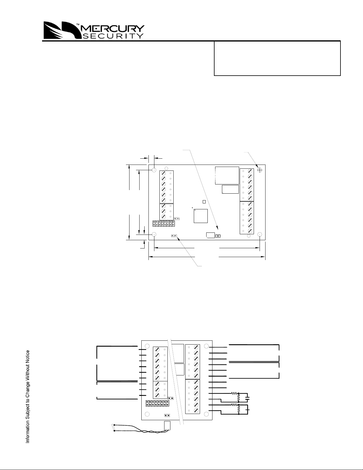
MR50 READER INTERFACE
Installation and Specifications:
1. General:
The MR50 reader interface provides a solution to the OEM system integrator for interfacing to a
TTL/Wiegand/RS-485 type reader and door hardware. The MR50 can accept data from a reader with
clock/data, Wiegand signaling or 2-wire RS-485, also provides a tri-stated LED control and buzzer
control. Two Form-C contact relay outputs may be used for strike control or alarm signaling. Two
inputs are provided for monitoring the door contact and exit push button. Communication to the
interface is accomplished via a 2-wire RS-485 interface. The MR50 requires 12 to 24 Vdc for power.
2. Power, Reader and Door Hardware Wiring:
All interconnections to the interface are via quick-disconnect terminal blocks. The MR50 requires
filtered 12 to 24 Vdc±10% for power. The MR50 supports clock/data, Wiegand or 2-wire RS-485
reader interface signaling. Two inputs are typically used for door contact and exit push button
monitoring. End of line resistors are required for line supervision.
Note: The input power is passed through to the reader terminal strip and is available for powering a
reader. Care must be taken to insure that the input voltage is within the voltage range of the reader.
Mercury Security Corporation © 2014 MR50 DOC 10107-0009 REV 2.03 Page 1
Page 2
ADDRESS 0
MR-DT
RS-485 MODE
9600 BAUD
READER PORT
2-WIRE RS-485
12Vdc (RED) (1)
TR+ (BLUE) (3)
TR- (GRAY) (4)
GROUND (BLACK) (2)
VO
TB4
GND
BZR
D0/DAT/T-
D1/CLK/T+
LED
RED (1)
GRN (2)
BLK (6)
ORG (5)
WHT (3)
BRN (4)
READER PORT
2-WIRE RS-485
GND
D0/DAT/T-
D1/CLK/T+
VO
LED
TB4
BZR
MR-10/20 READER
DATA1/DATA0 - CLOCK/DATA 2-WIRE RS-485
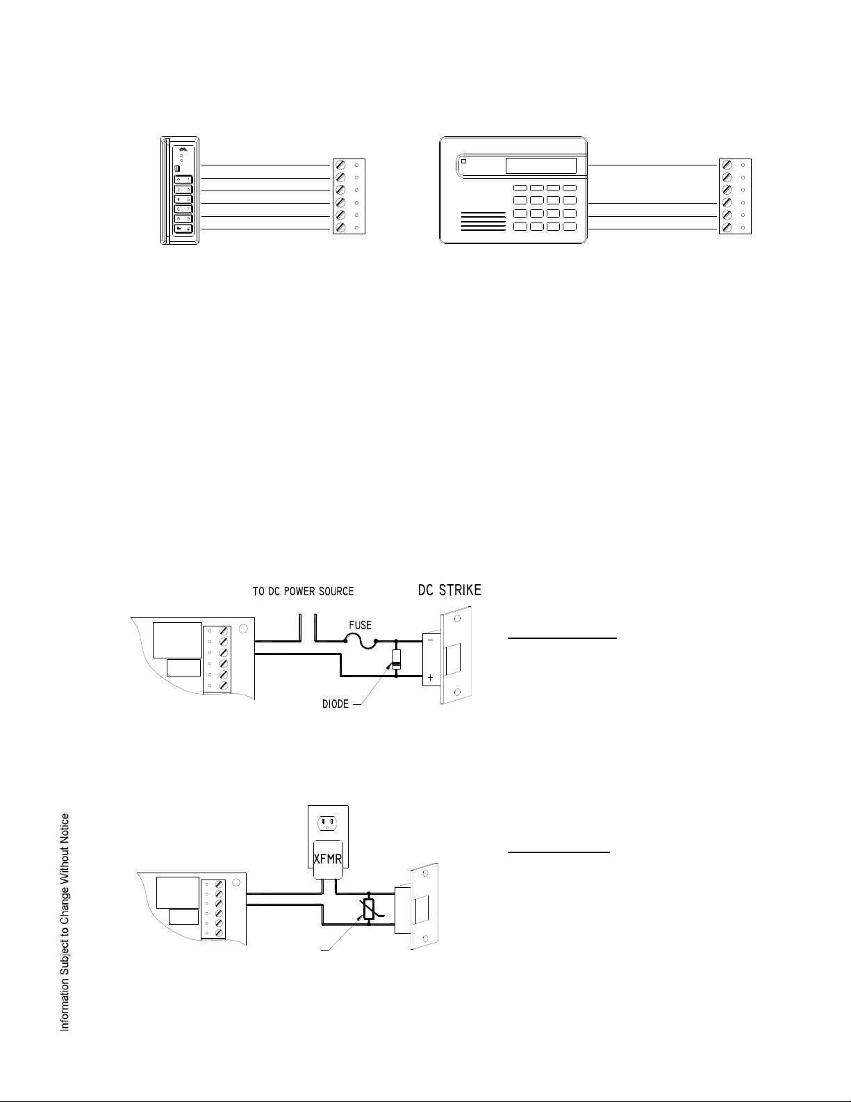
Diode Selection:
Diode current rating: 1x strike current
Diode breakdown voltage: 4x strike voltage
For 12 Vdc or 24 Vdc strike, diode 1N4002
(100V/1A) typical
MOV Selection:
Clamp voltage: 1.5x Vac RMS.
For 24 Vac strike, Panasonic:
ERZ-C07DK470 typical
TB3
K2
K1
C
NC
NO
C
NO
NC
K2K1
TB3
K2
K1
C
NC
NO
C
NO
NC
K2K1
Reader Wiring:
Door Strike Relay Wiring:
Two Form-C contact relays are provided for controlling door strike or other devices. The contact
ratings are 5 A for relay K1 and 1 A for relay K2. Load switching can cause abnormal contact wear
and premature contact failure. Switching of inductive loads (strike) also causes EMI (electromagnetic
interference) which may interfere with normal operation of other equipment. To minimize premature
contact failure and to increase system reliability, contact protection circuit must be used. The
following two circuits are recommended. Locate the protection circuit as close to the load as possible
(within 12 inches [30 cm]), as the effectiveness of the circuit will decrease if it is located far away.
Mercury Security Corporation © 2014 MR50 DOC 10107-0009 REV 2.03 Page 2
Page 3

MR-50 CONTROLLER
TO ADDITIONAL
SIO UNITS
J3
7
TR+
TB1
3
J2
2
1
6
5
4
GND
TR-
DAT
VO
D0
J4
8
J3
7
TB1
3
2
J2
1
6
5
4
TR+
GND
TR-
8
J4
DAT
VO
D0
TR-
GND
TR+
MR-50
LAST UNIT ON
COMMUNICATION
LINE - TERMINATOR
INSTALLED
3. Communication to a Controller:
The MR50 communicates to a Mercury Security intelligent controller (EP2500 for example) via a half
duplex multi-drop 2-wire RS-485 interface. The total cable length is limited to 4,000 feet (1,219
meters). Shielded cable of 24 AWG with characteristic impedance of 120 ohm is specified for the 2wire RS-485 interface. The last device on each end of the communication line should have the
terminator installed (set jumper J4 on).
Address, Baud Rate and Encryption Configuration Jumpers:
Each Interface (MR50, MR52, etc.) must be configured to have a unique address and correct baud
rate. The address and baud rate are selected by installing the specified jumpers.
Note 1: Firmware revisions prior to 1.39.1, the 115200 baud rate setting is 2400 baud.
Note 2: Firmware revisions prior to 1.39.1, jumper 8 is not defined, remove jumper.
Mercury Security Corporation © 2014 MR50 DOC 10107-0009 REV 2.03 Page 3
Page 4

4. Status LEDs:
Power-up: All LED’s OFF.
Initialization: Once power is applied, initialization of the module begins.
The A LED is turned ON at the beginning of initialization.
Run time: After a successful initialization, the LEDs have the following meanings:
A LED: Heartbeat and On-Line Status:
Off-line: 1 second rate, 20% ON
On-line:
Non-encrypted communication: 1 second rate, 80% ON
Encrypted communication:
.1 S ON, .1 S OFF, .1 S ON, .1 S OFF, .1 S ON, .1 S OFF, .1 sec ON, .3 S OFF
A LED Error Indication:
Waiting for application firmware to be downloaded: .1 S ON, .1 S OFF.
B LED: SIO Communication Port Status:
Indicates communication activity on the SIO communication port
5. Specifications:
The Interface is for use in low voltage, class 2 circuits only.
Primary Power: 12 to 24 Vdc ± 10%, 150 mA maximum (plus reader current)
12 Vdc @ 110 mA (plus reader current) nominal
24 Vdc @ 60 mA (plus reader current) nominal
Outputs: 2, Form-C contact relays: K1: 5 A @ 30 Vdc, K2: 1 A @ 30 Vdc
Inputs: 2 unsupervised/supervised, standard EOL, 1k/2k ohm, 1% 1/4 watt
1 unsupervised, dedicated for cabinet tamper
Reader Interface:
Reader power: 12 to 24 Vdc±10% (input voltage passed through)
Reader LED output: TTL compatible, high > 3 V, low < 0.5 V, 5 mA source/sink maximum
Buzzer output: Open collector, 5 Vdc open circuit maximum, 10 mA sink maximum
Data Inputs: TTL compatible, mag stripe and Wiegand standards supported.
RS-485 Mode: 9600 bps, asynchronous, half-duplex, 1 start bit, 8 data bits, and 1
stop bit. Maximum cable length: 2000 ft (609.6m)
Communication: 2-wire RS-485: 9600, 19200, 38400 or 115200 bps
Cable Requirements:
Power: 18 AWG, 1 twisted pair
RS-485 I/O devices: 24 AWG, 120 ohm impedance, twisted pair with shield, 4,000 ft
(1,219 m) maximum
Alarm Inputs: 1 twisted pair per input, 30 ohms maximum, typically 22 AWG @
1000 ft (304.8 m)
Outputs: As required for the load
Reader data (TTL): 18 AWG, 6 conductor, 500 ft (150 m) maximum
Reader data (RS-485): 24 AWG, 120 ohm impedance, twisted pair with shield, 2,000 ft
(609.6 m) maximum
Mechanical:
Dimension: 4.25 in (108 mm) W x 2.75 in (70 mm) L x 1 in (25.4mm) H
Weight: 4 oz. (120 g) nominal
Mercury Security Corporation © 2014 MR50 DOC 10107-0009 REV 2.03 Page 4
Page 5

Specifications (continued):
Environment:
Temperature: -55 to +85 °C, storage, -40 to +75 °C, operating
Humidity: 10 to 95% RHNC
Warranty
Mercury Security warrants the product is free from defects in material and workmanship under normal use
and service with proper maintenance for one year from the date of factory shipment. Mercury Security
assumes no responsibility for products damaged by improper handling or installation. This warranty is
limited to the repair or replacement of the defective unit.
There are no expressed warranties other than set forth herein. Mercury Security does not make, nor
intends, nor does it authorize any agent or representative to make any other warranties, or implied
warranties, and expressly excludes and disclaims all implied warranties of merchantability or fitness for a
particular purpose.
Returns must be accompanied by a Return Material Authorization (RMA) number obtained from customer
service, and prepaid postage and insurance.
Liability
The Interface should only be used to control exits from areas where an alternative method for exit is
available. This product is not intended for, nor is rated for operation in life-critical control applications.
Mercury Security is not liable under any circumstances for loss or damage caused by or partially caused
by the misapplication or malfunction of the product. Mercury Security’s liability does not extend beyond
the purchase price of the product.
Mercury Security Corporation © 2014 MR50 DOC 10107-0009 REV 2.03 Page 5
 Loading...