

Page 1
www.mercury-security.com
2355 MIRA MAR AVE. LONG BEACH, CA 90815-1755, (562)986-9105 FAX (562) 986-9205
This device complies with part 15 of the FCC Rules.
Operation is subject to the following two conditions: (1) This
device may not cause harmful interference, and (2) this
device must accept any interference received, including
interference that may cause undesired operation.
12 TO 24Vdc
GND
VIN
+
-
TB11
MR16out PROCESSOR
6.00 [152.40]
5.50 [139.70].25 [6.35]
2.00 [50.80]3.00 [76.20]2.00 [50.80]
8.00 [203.20]
S1
1
1 2 43 5 12976 8 13 1410 11 15 16
TB10
TR+
GND
R+
4W
R-
2W
TR-
RS-485
GND
VIN
GND
BA
CT
GND
TB9
TB11
J2
J1
J1, J2
RS-485
TERM
NC
C
NO
NC
C
NO
OUT 8
OUT 7
TB4 K8
NO
C
NC
NO
C
NC
OUT 6
OUT 5
NO
C
NC
NO
C
NC
OUT 4
OUT 3
NO
C
NC
NO
C
NC
OUT 2
OUT 1
TB3K7 TB2 TB1
2W
4W
J3
U1
J6
J5
J7
J8
J4
A
B
CT
BA
2
3
4
5
6
7
8
K2
K4
K3
K1
K9
K11
K12
K10
K5
K13
K14
K15
K16
TB5
TB6
TB7
TB8
NO
C
NC
NO
C
NC
OUT 9
OUT 10
C
NO
NC
C
NO
NC
OUT 11
OUT 12
NC
C
OUT 13
NO
NC
OUT 14
NO
C
OUT 16
NO
C
OUT 115
NC
C
NO
NC
K6
POWER IN
12-24Vdc
SIO COMMUNICATION
PORT, RS-485
TAMPER AND POWER
MONIOTR INPUTS
DIP SWITCHES
STATUS LEDs
Ø.156 [Ø4.0]
8 PLACES
OUTPUTS
OUTPUTS
RELAY STATUS LEDs
.50 [12.70]
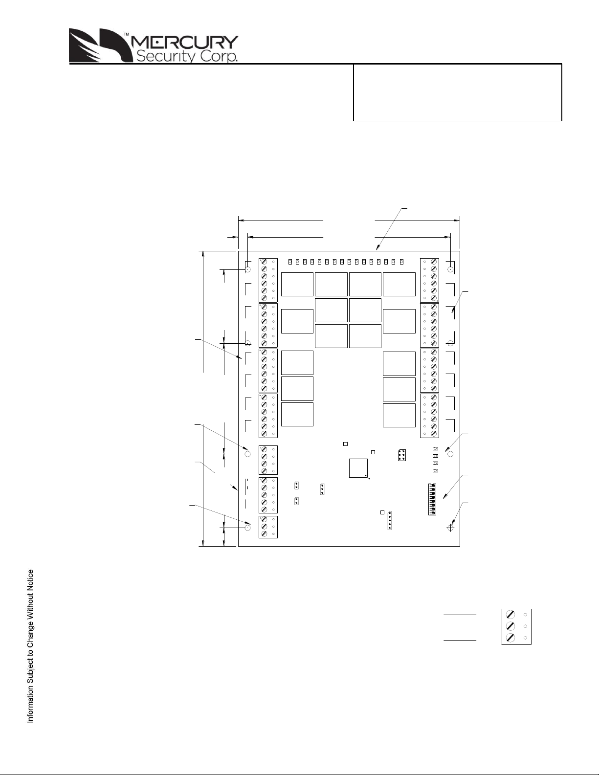
Installation and Specifications:
1. General:
The MR16out processor provides a solution to the OEM system integrator for output control. The
controller has 16 form-C contact relays for load switching. Additionally, 2 digital inputs are provided for
tamper and power fault status monitoring. The processor requires 12 to 24Vdc for power.
2. Supplying Power to the MR16out:
The MR16out requires 12 to 24Vdc for power on TB11. Locate power
source as close to the unit as possible. Connect power with minimum of
18AWG wires.
Observe POLARITY on VIN!
Mercury Security Corporation © 2009 MR16out DOC 10107-0012 REV 2.01 Page 1
Page 2
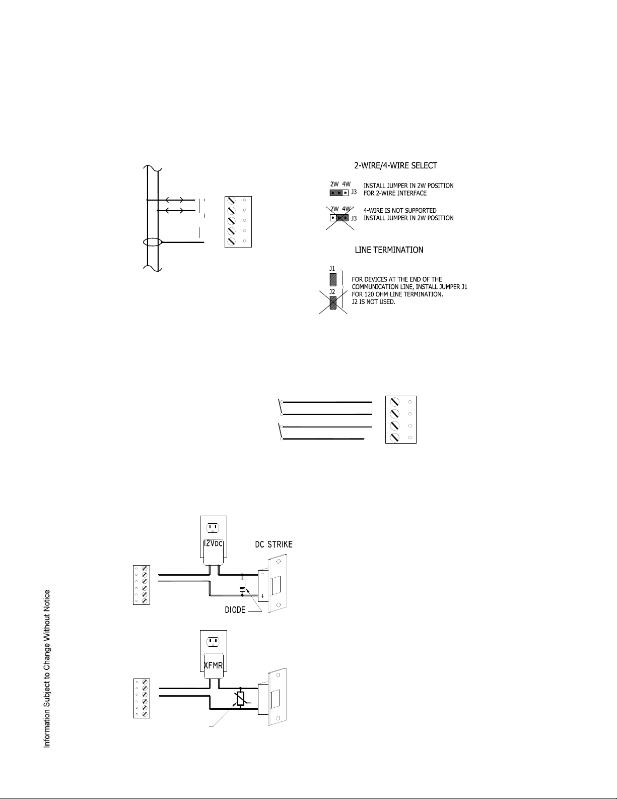
DIODE SELECTION:
DIODE CURRENT RATING > 1 X STRIKE CURRENT
DIODE BREAK DOWN VOLTAGE: 4X STRIKE VOLTAGE
FOR 12Vdc or 24Vdc STRIKE, DIODE 1N4002 (100V /1A)
TYPICAL
MOV SELECTION:
CLAMP VOLTAGE > 1.5 X Vac RMS
FOR 24Vac STRIKE, PANASONIC ERZ-C07DK470
TYPICAL
CT
GND
BA
GND
CABINET
TAMPER
POWER
FAULT
TB9
NC
C
NO
NC
C
NO
NC
C
NO
NC
C
NO
TR+
TR-
R+
R-
GND
2W
4W
2-WIRE
TB10
(ONLY 2-WIRE RS-485 IS SUPPORTED)
3. Communication Wiring:
The MR16out communicates to a controller via a 2-wire RS-485 interface. The interface allows multi-drop
communication on a single bus of up to 4,000 feet (1,200 m). Use twisted pair (minimum 24 AWG) with
shield for the communication line.
Install the following jumpers for the RS-485 interface according to the selected configuration:
4. Inputs for Cabinet Tamper/Power Fault:
Input CT and input BA are used for monitoring cabinet tamper and power failure with normally closed
contacts. These two inputs are for contact closure monitoring only, and do not use EOL resistor(s). If
these inputs are not used, install a short piece of wire at the input to indicate a safe condition.
5. Relay Outputs:
The following diagrams show typical use of the relay. A DC power source is recommended whenever
possible. Transient clamping must be provided to protect the contacts and to reduce EMI emission. Use
sufficiently large wires for the load current to avoid voltage loss.
Mercury Security Corporation © 2009 MR16out DOC 10107-0010 REV 2.01 Page 2
Page 3

S8
S7
S6
S5
S4
S3
S2
S1
SELECTION
OFF
OFF
OFF
OFF
OFF
Address 0
OFF
OFF
OFF
OFF
ON
Address 1
OFF
OFF
OFF
ON
OFF
Address 2
OFF
OFF
OFF
ON
ON
Address 3
OFF
OFF
ON
OFF
OFF
Address 4
OFF
OFF
ON
OFF
ON
Address 5
OFF
OFF
ON
ON
OFF
Address 6
OFF
OFF
ON
ON
ON
Address 7
OFF
ON
OFF
OFF
OFF
Address 8
OFF
ON
OFF
OFF
ON
Address 9
OFF
ON
OFF
ON
OFF
Address 10
OFF
ON
OFF
ON
ON
Address 11
OFF
ON
ON
OFF
OFF
Address 12
OFF
ON
ON
OFF
ON
Address 13
OFF
ON
ON
ON
OFF
Address 14
OFF
ON
ON
ON
ON
Address 15
ON
OFF
OFF
OFF
OFF
Address 16
ON
OFF
OFF
OFF
ON
Address 17
ON
OFF
OFF
ON
OFF
Address 18
ON
OFF
OFF
ON
ON
Address 19
ON
OFF
ON
OFF
OFF
Address 20
ON
OFF
ON
OFF
ON
Address 21
ON
OFF
ON
ON
OFF
Address 22
ON
OFF
ON
ON
ON
Address 23
ON
ON
OFF
OFF
OFF
Address 24
ON
ON
OFF
OFF
ON
Address 25
ON
ON
OFF
ON
OFF
Address 26
ON
ON
OFF
ON
ON
Address 27
ON
ON
ON
OFF
OFF
Address 28
ON
ON
ON
OFF
ON
Address 29
ON
ON
ON
ON
OFF
Address 30
ON
ON
ON
ON
ON
Address 31
OFF
OFF 115,200 BPS, See note 1 below.
OFF
ON
9,600 BPS
ON
OFF
19,200 BPS
ON
ON
38,400 BPS
OFF
Encrypted communication not required
See note 2 below.
ON
Encrypted communication required
See note 2 below.
6. DIP Switch and Jumper Usage:
Switches 1 to 5 select the device address. Switch 6 and 7 select the communication baud rate. Switch 8
enables encrypted communication. All other configuration settings are set via host software.
Note 1: Firmware revisions prior to 1.30.1, this setting is 2,400 BPS.
Note 2: Firmware revisions prior to 1.30.1, SW8 is not defined. Set to the OFF position.
Mercury Security Corporation © 2009 MR16out DOC 10107-0010 REV 2.01 Page 3
Page 4

JUMPER
DESCRIPTION
J1
RS-485 termination, install in first and last units only
J2
Not used
J3
2-wire/4-wire select, install in 2W position only
J4
Factory use only
J5
Factory use only
J6
Factory use only
J7
Factory use only
J8
Factory use only
J9
Factory use only
Jumpers:
7. Status LEDs:
Power-up: All LED’s OFF
Initialization: Once power is applied, initialization of the module begins
When initialization is completed, LEDs A, B, CT, and BA are briefly sequenced ON then OFF.
Run time: After the above sequence, the LEDs have the following meanings:
A LED: Heartbeat and On-Line Status:
Off-line: 1 sec rate, 20% ON
On-line:
Non-encrypted communication: 1 sec rate, 80% ON
Encrypted communication:
.1 sec ON, .1 sec OFF, .1 sec ON, .1 sec OFF, .1 sec ON, .1 sec OFF, .1 sec ON, .3 sec OFF
A LED Error Indication:
Waiting for application firmware to be downloaded: .1 sec ON, .1 sec OFF.
B LED: SIO Communication Port Status:
Indicates communication activity on the SIO communication port
CT: Cabinet Tamper
BA: Power Fault
LED 1 through 16: Illuminates when output relay OUT 1 (K1), OUT 2 (K2) is energized and so on.
Mercury Security Corporation © 2009 MR16out DOC 10107-0010 REV 2.01 Page 4
Page 5

8. Specifications:
The MR16out is for use in low voltage, class 2 circuits only.
Primary power: 12 to 24Vdc ±10%, 1100mA maximum
12Vdc @ 850mA nominal
24Vdc @ 450mA nominal
Relay contacts: 16 Form-C, 5A @ 30Vdc, resistive
Inputs: 2 unsupervised, dedicated for cabinet tamper and UPS fault monitoring
Communication: RS-485, 2-wire. 9600, 19200, 38400, or 115200 bps
Cable requirements:
Power: 1 twisted pair, 18 AWG
RS-485: 24AWG, 120 ohm impedance, twisted pair with shield, 4,000' (1,200m)
maximum
Inputs: 1 twisted pair, 30 ohms maximum
Outputs: As required for the load
Mechanical:
Dimension: 6" (152mm)W x 8" (203mm)L x 1" (25.4mm)H
Weight: 14 oz. ( 400 gm) nominal
Environmental:
Temperature: -55°C to +85°C, storage
0°C, to +70°C, operating
Humidity: 0% to 95% RHNC
Warranty:
Mercury Security Corporation warrants the product is free from defects in material and workmanship under normal
use and service with proper maintenance for one year from the date of factory shipment. Mercury Security
Corporation assumes no responsibility for products damaged by improper handling or installation. This warranty is
limited to the repair or replacement of the defective unit.
There are no expressed warranties other than set forth herein. Mercury Security Corporation does not make, nor
intends, nor does it authorize any agent or representative to make any other warranties, or implied warranties, and
expressly excludes and disclaims all implied warranties of merchantability or fitness for a particular purpose.
Returned units are repaired or replaced from a stock of reconditioned units. Returns must be accompanied by a
return authorization number (RMA) obtained from customer service, and prepaid postage and insurance.
Liability:
The Interface should only be used to control exits from areas where an alternative method for exit is available. This
product is not intended for, nor is rated for operation in life-critical control applications. Mercury Security Corporation
is not liable under any circumstances for loss or damage caused by or partially caused by the misapplication or
malfunction of the product. Mercury Security Corporation's liability does not extend beyond the purchase price of the
product.
Mercury Security Corporation © 2009 MR16out DOC 10107-0010 REV 2.01 Page 5
 Loading...