

Page 1
KWX - 2.4 GHz Wireless 485 Network Transceiver
Quick Start Guide
Keri’s KWX Wireless Transceivers allow you to easily create a wireless communication network
between PXL controllers in an RS-485 network. Just as in wired controller networks, the KWX works
on systems as simple as two or three doors, all the way up to 256 door systems, and in distances of up
to a mile between controllers when using long-range antennas.
KWX Wireless T ransceivers ope rate in
a frequency hopping mode in the 2.4
GHz ISM band. Standard units have a
nominal range of 55 meters (180 feet).
Three antenna options are available,
extending the range of the wireless
units.
Controller networks can use a
combination of KWX units and RS485 2-conductor, shielded, twisted-pair
cabling, allowing you to mix and
match wired and wireless connections
to create the fastest and most
economical Keri Access Control
installation. The KWX connection to
the controller uses the same type of
cabling as in standard wired
connections.
Keri’s KWX W ireless Transceivers are
compatible with PXL-500/510, PXL250, and Entraguard controllers,
allowing these transceivers to be added
to existing networks as well as be used
in new installations.
RS-485 Wireless Transceiver
Page 1 of 14 P/N: 01949-002 Rev. A
Page 2

KWX - 2.4 GHz Wireless 485 Network Transceiver
Quick Start Guide
1.0 System Components
KWX Units
KWX units can be connected to any point in an RS-485 network line; one unit per network line. One
unit, connected to the network line with the master controller, must be mounted in a central location
that allows all other KWX units (connected to individual controller network spur lines) to
communicate with this central unit. All wireless units have an integrated omni-directional antenna
providing a “doughnut-shaped” coverage pattern (see Figure 10 on page 13).
NOTE: For proper operation between master contr oller and KWX unit, the master contr oller must be
a PXL-500 with firmware version 8.4.20 or greater. Entraguard controllers cannot be the master
controller.
Long-Range Antennas
The KWX unit is shipped with a unity gain “rubber-ducky” antenna. This antenna is mounted directly
onto the unit, and is not designed to be removed and relocated. Three optional antennas are available
for applications requiring separate antenna mounting or communication over longer distances. 1.8
meter (six foot) extention cables are available for these optional antennas, providing greater
flexibility in mounting location. These cables are specifically manufactured to minimize the amount
of signal loss over the length of the cable.
NOTE: Please contact Keri Systems if a cable length greater than 1.8 meters is required.
Unity Gain, Omnidirectional – Recommended for use in areas where it is not practical to mount the
KWX unit itself (i.e. outdoors, restricted space locations). Being omnidirectional, this antenna has the
same coverage pattern as the standard, rubber-ducky antenna (see Figure 10 on page 13).
6 db Gain, Omnidirectional – Increases the coverage area of a KWX unit by approximately 25%
(increasing to approximately 69 meters - 225 feet). When properly mounted, this antenna can help
resolve fringe-area coverage problems. Being omnidirectional, this antenna has the same coverage
pattern as the standard, rubber-ducky antenna, but with increased coverage in all directions (see
Figure 10 on page 13).
13.9 db Gain, Directional Yagi – Intended for use in outdoor, point-to-point applications such as
between distant buildings. The coverage distance is approximately twice that of the rubber-ducky –
110 meters (360 feet) using one Yagi antenna (with the Yagi antenna at the remote site) and up to 200
meters (650 feet) with Yagi antennas used at both ends. However, the coverage area is limited to a
very narrow, line-of-sight, antenna-to-antenna pattern (see Figure 11 on page 13). A Yagi antenna
cannot be used as a general replacement for the standard, rubber-ducky antenna.
When considering an optional antenna, please contact Keri headquarters with your requirements so
we can help match the proper antenna with your needs.
Page 2 of 14 P/N: 01949-002 Rev. A
Page 3
KWX - 2.4 GHz Wireless 485 Network Transceiver
Quick Start Guide
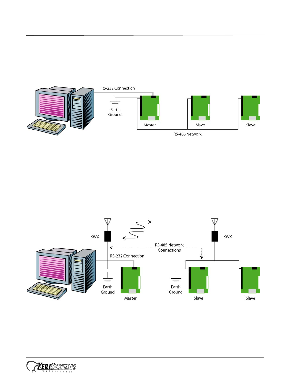
2.0 Controller Network Configurations
The use of KWX Wireless T ransceivers provide you with flexibility in designing a controller network
configuration. The network wiring for a standard hard-wired 485 controller network appears as
shown in Figure 1. In this configuration, each controller must be connected together via daisychained, RS-485 cabling.
Figure 1: Standard, Hard-Wired 485 Network
The layout for Keri’s KWX Wireless Transceiver networks, however, can take a variety of forms,
using multiple spurs and multiple wireless units, with each network spur being independent and the
wireless unit attached at any point within the spur. This allows for shorter, more flexible network
cable runs, and makes it possible to avoid difficult cable routing locations.
NOTE: A requirement for multiple wireless spurs is that each spur be earth grounded.
Examples of multiple spur/multiple unit networks are shown in Figures 2, 3, and 4.
Figure 2: Basic KWX Wireless Transceiver Network
Page 3 of 14 P/N: 01949-002 Rev. A
Page 4
KWX - 2.4 GHz Wireless 485 Network Transceiver
Quick Start Guide
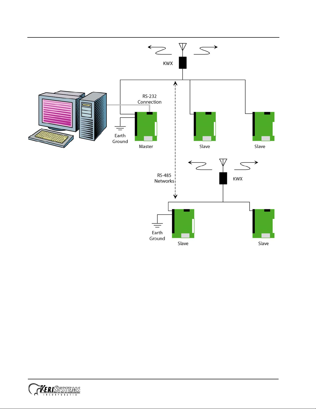
Figure 3: Wired Network with KWX Wireless Spur Configuration
Page 4 of 14 P/N: 01949-002 Rev. A
Page 5
KWX - 2.4 GHz Wireless 485 Network Transceiver
Quick Start Guide
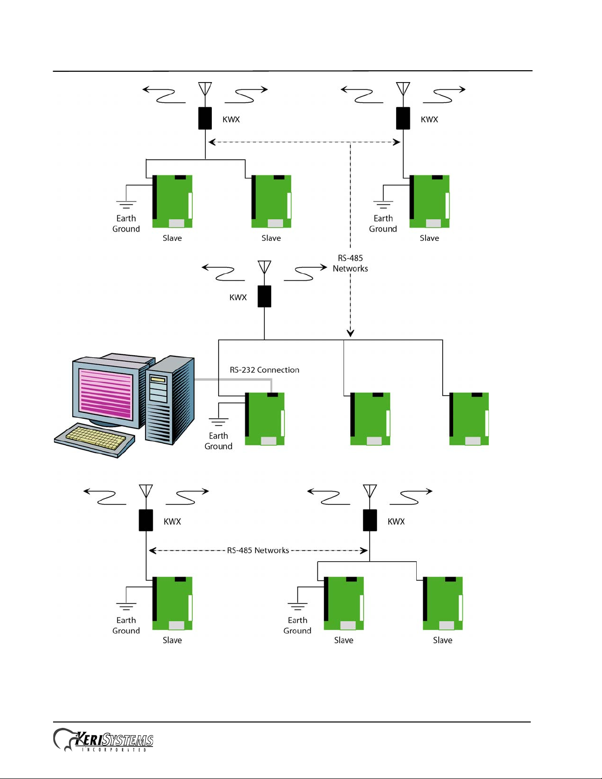
Figure 4: Wired Network with Multiple KWX Wireless Spurs Configuration
Page 5 of 14 P/N: 01949-002 Rev. A
Page 6

KWX - 2.4 GHz Wireless 485 Network Transceiver
Quick Start Guide
3.0 System Limitations
Radio frequency transmissions are subject to various types of interference not normally encountered
on copper wire. This can have the net effect of slower data transfers and an occasional missed
transmission. Because of these possibilities there may be certain limitations in system using KWX
units.
Monitor Mode
Monitor Mode provides the greatest level of data transmission stress to the access control system.
Long-term Monitor Mode operation is dependant upon the signal strength of the KWX units. At a
lower signal strength, it is possible that a communication error may occur when transferring large
amounts of data. While the access control system is designed to not lose events stored in the
controllers’ event buffers, Monitor Mode may miss displaying an event during high data transfer
periods. For this reason, Keri recommends operating in Monitor Mode at a minimum when using
KWX units.
Automatic Dial-Up When Buffer Full
This feature allows a controller to automatically contact Doors and upload its event database once a
certain memory threshold in the controller is reached. When this occurs, a large amount of data is
transmitted in a steady stream. To protect event data integrity, Keri recommends either disabling this
feature and periodically, manually collecting event data from controllers or reducing the event
collection threshold to 50% (resulting in more frequent data collection with smaller event data files).
Page 6 of 14 P/N: 01949-002 Rev. A
Page 7

KWX - 2.4 GHz Wireless 485 Network Transceiver
Quick Start Guide
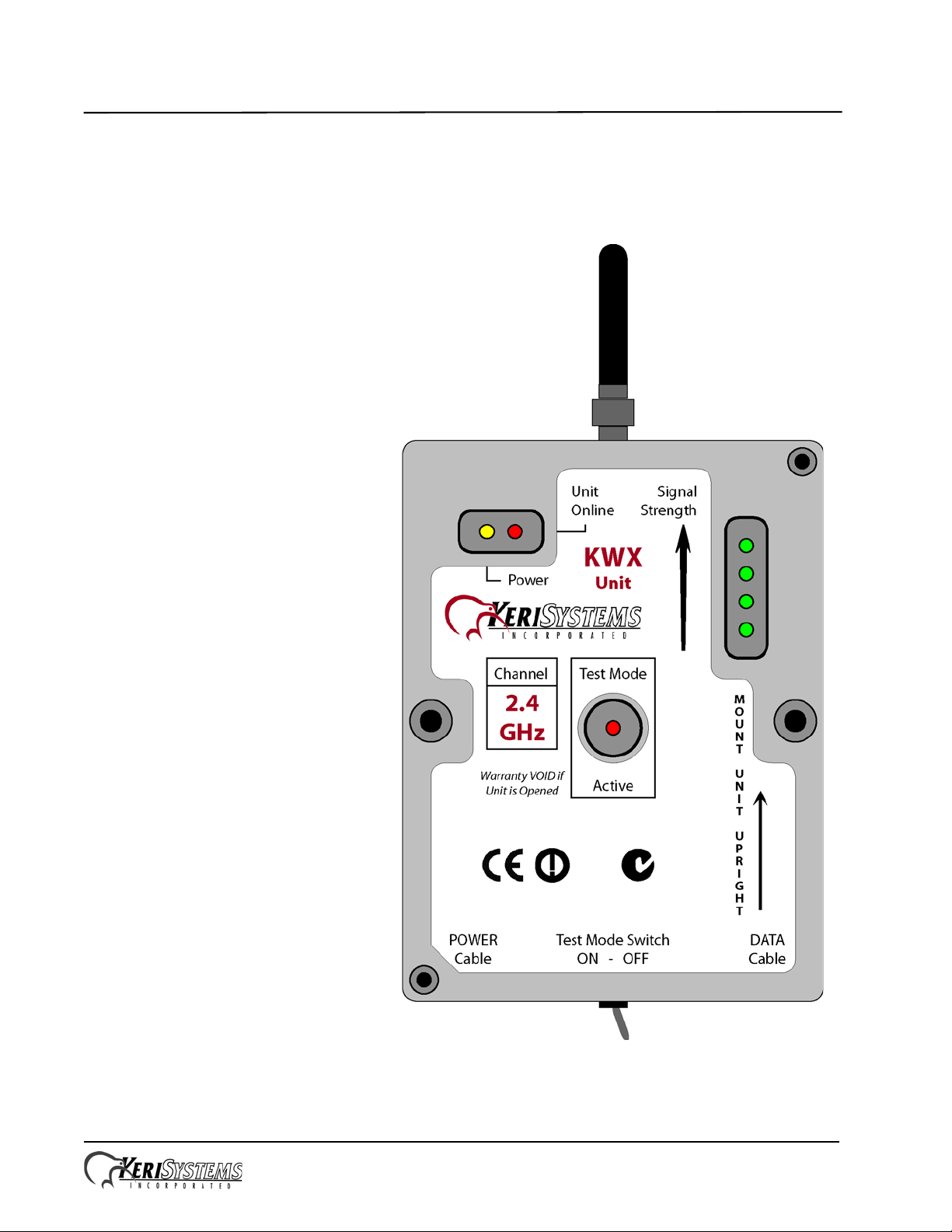
4.0 Site Survey
Prior to installation, a site survey should be conducted to ensure proposed KWX installation locations
will provide the required site coverage. This is done using two KWX units. Refer to Figure 5 for unit
power wiring and LED functions.
NOTE: Using more than two units for the site survey invalidates the results of the survey. Only two
units are necessary and only two should be used.
Figure 5: Pre-Installation Test Unit Power Connections
Page 7 of 14 P/N: 01949-002 Rev. A
Page 8

KWX - 2.4 GHz Wireless 485 Network Transceiver
Quick Start Guide
1. Take the KWX unit to be connected to the master controller and designate this unit the Master
Transceiver.
2. Position the Master Transceiver in the desired location near the master controller location using
the following criterion:
- Mount the unit at least 7 feet above the floor; the higher the unit is mounted, the greater the
signal strength.
- The unit must be mounted upright for proper signal coverage (refer to the unit label – see
Figure 5 on page 7).
- Do not mount the unit on to or beside metal and ensure the unit is not obscured by large metal
objects (such as HVAC units and ducts, building supports and poles, etc.).
- Ensure you will be able to route the unit cables to the controller.
The Master Transceiver must be located central to all Remote Transceivers. All Transceiver
communication occurs between the Master and the Remote Transceivers. Remote T ransceivers do
not communicate with each other.
3. Provide 12 VDC power to the Master Transceiver using a gel cell battery or a DC power supply.
The Power LED will light-up solid amber.
4. Turn the Test Mode Switch ON. The Test Mode Active LED will flash red and the Master
Transceiver will begin transmitting test data packets.
5. Take a second KWX unit and designate this unit the Remote Transceiver. Leave the Test Mode
Switch on the Remote Transceiver OFF.
6. Position the Remote Transceiver in a desired mounting location near a controller on an access
control network spur using the same criterion as in Step 2. The two units must be mounted greater
than 10 feet apart.
NOTE: Transcievers must be placed greater than 10 feet apart from each other. Unit-to-unit
interference may be generated if units are placed closer than 10 feet from each other.
7. Provide 12 VDC power to the Remote Transceiver using a gel cell battery or a 12 VDC power
supply. The Power LED will light-up solid amber.
8. Ensure the Test Mode Switch on the Remote Transceiver is OFF.
Page 8 of 14 P/N: 01949-002 Rev. A
Page 9

KWX - 2.4 GHz Wireless 485 Network Transceiver
Quick Start Guide
9. Note the number of green Signal Strength LEDs that are lit.
- If no LEDs are lit, you are out of the useable range of the Master Transceiver.
- If one LED is lit, you are in a weak signal area, receiving the minimum signal from the Master
Transceiver.
- The more LEDs that are lit, the better the signal being received from the Master Transceiver.
10. Move the Remote Transceiver unit one to two feet around the mounting location to locate the area
that provides the greatest signal strength and to ensure this mounting location is not a fringe
location. For reliable operation, you should have two or more LEDs lit.
NOTE: Do NOT remove the attached antenna fr om the KWX unit and attempt to relocate the antenna
using coax cabling. The unit is designed specifically for the provided antenna in its mounted location.
11. When a satisfactory mounting location is found, mark the area.
12. Repeat Steps 6 through 11 for each mounting location for each access control network spur.
NOTE: Common electrical devices can affect the site survey process, as well as unit operation. For
instance, a 2.4 GHz wireless telephone is an example of a common device that can interfere with
KWX units.
Page 9 of 14 P/N: 01949-002 Rev. A
Page 10

KWX - 2.4 GHz Wireless 485 Network Transceiver
Quick Start Guide
5.0 Unit Mounting and Wiring Instructions
Once mounting locations have been identified via the site survey , the KWX units can be mounted and
then wired in the identified areas.
5.1 Mounting the Unit
Mounting can be done in two ways. The simplest is to mount the unit directly to the wall using a piece
of double-stick, foam tape (see Figure 6).
If more secure mounting is desired, the unit can be mounted directly to the wall using two screws
through the two mounting holes in the body of the unit (see Figure 7).
Figure 6: Wall Mounting Using
Double-Stick Tape
Figure 7: Direct Enclosure Mounting
Page 10 of 14 P/N: 01949-002 Rev. A
Page 11

KWX - 2.4 GHz Wireless 485 Network Transceiver
Quick Start Guide
5.2 Wiring the Unit
Keri KWX units have two cables: one for the power and one for network data.
5.2.1 Unit Power
Connect the power cable to either a controller or to a 12 VDC power supply as shown in Figure 8. The
yellow power LED will be ON. Choose the type of connection based on the length of the run; the
longer the run the greater the IR voltage drop at the end of the run. For reliable operation, the voltage
measured at the unit should be 10 VDC or greater.
Figure 8: Power Wiring Diagram
Page 11 of 14 P/N: 01949-002 Rev. A
Page 12

KWX - 2.4 GHz Wireless 485 Network Transceiver
Quick Start Guide
5.2.2 RS-485 Network Connections
Connect the network data line as shown in Figure 9.
Figure 9: RS-485 Network Wiring Diagram
Page 12 of 14 P/N: 01949-002 Rev. A
Page 13

KWX - 2.4 GHz Wireless 485 Network Transceiver
Quick Start Guide
6.0 NOTES
Antenna Coverage Patterns:
Figure 10: Omni-directional Antenna Coverage Pattern
Figure 11: Yagi Antenna Point-to-Point Coverage Pattern
Page 13 of 14 P/N: 01949-002 Rev. A
Page 14

KWX - 2.4 GHz Wireless 485 Network Transceiver
Quick Start Guide
Contact Keri Systems:
Keri USA Keri UK, Ireland, Europe
2305 Bering Drive
San Jose, CA 95131
Telephone: (800) 260-5265
(408) 435-8400
Fax: (408) 577-1792 Fax: + 44 (0) 1763 274 106
Web: www.kerisys.com Web: www.kerisystems.co.uk
E-mail: sales@kerisys.com
techsupport@kerisys.com
Unit 17
Park Farm Industrial Estate
Ermine Street
Buntingford
Herts SG9 9AZ UK
Telephone: + 44 (0) 1763 273 243
E-mail: sales@kerisystems.co.uk
tech-support@kerisystems.co.uk
End of document.
Page 14 of 14 P/N: 01949-002 Rev. A
 Loading...