

Page 1
MS-9000: MegaStar Reader
Quick Start Guide
MS-9000
The MS-9000 MegaStar Reader
The MS-9000 MegaStar Reader is intended for installation in proximity applications where an
extended read range is required. The reader provides an audio beeper and a multi colored LED
to annunciate the reader's status when used on a PXL-250, PXL-100, or IntelliProx.
• Amber – to indicate normal operation awaiting an access event
• Green – to indicate a valid card has been presented or the door has been unlocked for access
• Red – to indicate an invalid card has been presented or the door is in an alarm condition
The MS-9000 MegaStar Reader is housed in a black, weatherproof, shock resistant package.
The reader provides optimum performance when mounted at least ten inches away from metal
surfaces; read range is reduced if the reader is mounted on or near metal surfaces.
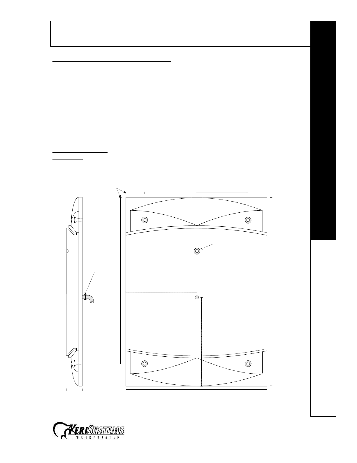
Specifications
Dimensions
• 8.50 inches High x 6.00 inches Wide x 0.75 inches Deep
• 21.59 cm High x 15.24 cm Wide x 1.91 cm Deep
Mounting Holes - 4x
1.90"
Drill Cable
Access Hole
0.375"
(3/8")
1.60"
12.15"
6.00" to
Cable Hole Center
8.85"
LED
16.00" H
7.50" to
Cable Hole Center
1.35" D 12.00" W
Figure 1 – MS-9000 Dimensions
1530 Old Oakland Road, Suite 100 01827-001 Rev. D
San Jose, CA 95112 USA
(800) 260-5265 (408) 451-2520 FAX (408) 441-0309 Page 1 of 6
Page 2
MS-9000: MegaStar Reader
Quick Start Guide
MS-9000
Operating Voltage
• 12v to 24v DC @ 200 ma
Cable Specifications
• up to 100 feet using six conductor, shielded, stranded AWG 24 wire
• up to 250 feet using six conductor, shielded, stranded AWG 22 wire
• up to 500 feet using six conductor, shielded, stranded AWG 18 wire
Mounting Instructions
Five holes need to be drilled to mount the MegaStar Reader (see Figure 1 on page 1). One hole
(0.375" – 3/8") accommodates the reader cable. Four holes are for mounting the reader on a wall
surface (hole size is dependent upon the size of the mounting screw – a 1/4" screw or bolt is
recommended).
For parking or related applications, the MegaStar Reader can be mounted to a metal "gooseneck" stand, provided the mounting surface on the stand is 4 inches x 4 inches or smaller. This
size restriction on the stand's mounting surface ensures the metal in the stand does not affect the
operation of the Reader. If the stand's mounting surface is greater than 4 inches x 4 inches a
mounting plate made of nonmetallic material is required between the stand's mounting surface
and the Reader to provide the necessary distance between Reader and metal to ensure optimum
read range.
Connections
The MegaStar Reader does not require configuration; there are no switches or jumpers to set.
The MegaStar Reader is normally connected to a PXL-250, PXL-100, or IntelliProx, but can be
connected to an alternative host controller/alarm panel through an IntelliProx used in its Wiegand
input device mode. All connections needed to support the reader are made through the reader's
cable. Please consult the tables on pages 2 and 3 for specific connection instructions.
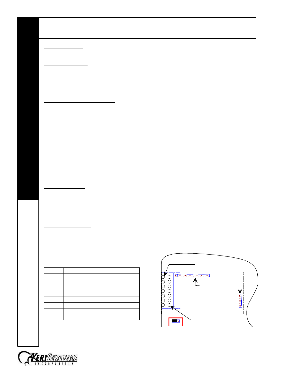
PXL-250 Connections
The "A" reader connects to TB5, pins 1 through 6 (TB5 has a seventh pin, but no connection is
made to that pin). The "B" reader connects to TB6, pins 1 through 6 (TB6 has a seventh pin, but
no connection is made to that pin).
Connecting to the PXL-250 – TB5 or TB6
Pin # Function Wire Color
1 Reader Antenna Blue
2 Beeper Green
3 Reader Power Red
4 Reader Ground Black
5 Green LED Brown
6 Red LED White
7 no connection –
4 Shield Silver
1
2
3
4
5
6
7
1
2
3
4
5
6
7
1 3
12V 5V
JP4
TB5 - "A" Reader
on the Motherboard
Receiver Board
Connectors to
the Motherboard
TB6 - "B" Reader
on the Receiver Board
1530 Old Oakland Road, Suite 100 01827-001 Rev. D
San Jose, CA 95112 USA
(800) 260-5265 (408) 451-2520 FAX (408) 441-0309 Page 2 of 6
Figure 2 – PXL-250 Connections
Page 3

MS-9000: MegaStar Reader
Quick Start Guide
MS-9000
Design 5 PXL-100 Connections
The "A" reader connects to TB2, pins 14 through 19. The "B" reader connects to TB3, pins 20
through 25.
Connecting to the PXL-100 – TB2
Pin # Function Wire Color
14 Green LED Brown
15 Beeper Green
16 Reader Power Red
17 Reader Ground Black
18 Reader Antenna Blue
19 Red LED White
17 Shield Silver
Connecting to the PXL-100 – TB3
14
15
16
17
18
19
S1
TB2
"A" Reader
Pin # Function Wire Color
20 Green LED Brown
21 Beeper Green
22 Reader Power Red
23 Reader Ground Black
24 Reader Antenna Blue
25 Red LED White
23 Shield Silver
Connections
NOTE: Please contact customer support at Keri Systems for information regarding connecting a
Reader to a Design 4 PXL-100. A Design 4 PXL-100 can be identified by the location of its power
connection made at the middle of the left edge of the printed circuit board.
IntelliProx Connections
The reader is connected to TB1, pins 1 through 6.
Connecting to the IntelliProx – TB1
Pin # Function Wire Color
1 Reader Antenna Blue
2 Beeper Green
3 Green LED Brown
4 Red LED White
5 Reader Power Red
6 Reader Ground Black
6 Shield Silver
20
21
22
23
24
25
Figure 3 – Design 5 PXL-100
1 2 3 4 5 6
TB1 - Reader
TB3
"B" Reader
TB2
7
8
Figure 4 – IntelliProx Connections
1530 Old Oakland Road, Suite 100 01827-001 Rev. D
San Jose, CA 95112 USA
(800) 260-5265 (408) 451-2520 FAX (408) 441-0309 Page 3 of 6
Page 4

MS-9000: MegaStar Reader
Quick Start Guide
MS-9000
24 VDC Power Option
Instead of the 12 VDC power provided by the controller or IntelliProx unit, the MegaStar Reader
can be powered by a 24 VDC linear, regulated power supply. The advantage to the 24 VDC
supply is that the read range is increased by approximately 20%. Perform the following steps to
use the 24 VDC power option.
1. Disconnect the power and ground leads from the controller or IntelliProx unit.
2. Connect the positive lead from the 24 VDC supply to the Red lead on the Reader cable.
3. Connect the negative lead from the 24 VDC supply to the Black lead on the Reader
cable.
4. Connect the ground lead from the 24 VDC supply to the power ground on the controller
or IntelliProx unit.
• TB2, pin 2 on the PXL-250
• TB4, pin 27 on the PXL-100
• TB2, pin 12 on the IntelliProx
Installation Verification
The following information applies to an installation with a Keri Systems controller or IntelliProx
unit. When used with an alternative host controller/alarm panel through an IntelliProx used in its
Wiegand input device mode, the actions of the reader's LED and beeper are controlled by the
alternative host controller/alarm panel and might not match those of a Keri Systems controller.
The reader's power is provided by the controller, so the reader is powered on when the controller
is powered on. The reader's normal state is to display a constantly on Amber LED as it waits for a
card or tag to be presented.
To verify the reader is functioning properly, pass a Keri Proximity Card or a Keri Key Tag within a
few inches of the reader. The reader will beep and either the Green or Red LED will flash
(depending upon whether or not the card/tag has been enrolled at the controller) and then return
to steady Amber.
To verify the reader's read range, hold a Keri Proximity Card or a Keri Key Tag parallel to the
reader, about 3 feet away and slowly draw the Card/Tag in toward the reader. Note the distance
when the reader recognizes the card. The MegaStar reader's range will be up to 22 inches (26
inches if using the 24 VDC power option) depending upon the installation conditions, the material
on which the reader is mounted, and whether it is a card or a tag being read. Due to the physical
size difference between cards and tags, cards provide approximately 50% greater read range
than tags.
Refer to the Troubleshooting the Reader Installation section if the reader is not functioning
properly.
1530 Old Oakland Road, Suite 100 01827-001 Rev. D
San Jose, CA 95112 USA
(800) 260-5265 (408) 451-2520 FAX (408) 441-0309 Page 4 of 6
Page 5

MS-9000: MegaStar Reader
Quick Start Guide
MS-9000
Troubleshooting the Reader Installation
Problem Probable Cause Corrective Action
The reader does
not recognize a
card/tag (no beep,
no LED flash).
The reader does
not recognize a
card/tag (no beep,
no LED flash).
1. One or more of the
reader's wiring
connections are
incorrect.
2. The reader is not
receiving proper
power from the
controller.
3. The reader is mounted
too close to a device
that radiates
electromagnetic
interference.
4. A jumper is not set
correctly on the
controller.
The reader has a
short read range.
1. The reader's controller
is not properly
grounded.
- continued next page -
• Power down the controller and verify
the wiring connections are correct for
the reader/controller combination per
the instructions provided in the
Connections section on pages 2 and 3.
• If powering the reader at 12 volts, verify
the voltage supplied by the controller is
at 12 VDC +/- 2 V.
• If powering the reader at 24 volts, verify
the voltage supplied to the reader is at
24 VDC +/- 2 V.
• Devices such as computer monitors
radiate electromagnetic interference
that affects read range. When possible,
relocate either the reader or the device
to provide a greater distance between
the two.
• For a PXL-250: Verify there is a jumper
across pins 1 and 2 of JP4 (refer to the
Technical Reference manual for more
information – Keri p/n 01836-001).
• For a PXL-100: If the controllers are
using TAP™ software, verify JP1 on the
controller and the jumper on the
Receiver card
both jumper pins. If the controllers are
using Doors™ software, verify JP1 on
the controller and the Receiver card
are not installed across both pins
(typically the jumper will be installed
onto one of the pins to keep it
available).
• For an IntelliProx: Verify there is not a
jumper across pins 1 and 2 of JP1
(typically the jumper can be installed
onto one of the pins to keep it
available).
• Ensure there is a quality earth ground
connection made to the controller. Refer
to the controller's documentation for
specific information regarding the earth
ground connection.
(1)
are installed across
(1)
(1) The receiver board's jumper is on the underside of the board. Gently pull the receiver board
away from the controller, verify the jumper setting is correct per your application, carefully
align the connectors on the receiver board with the pins on the controller, and gently push the
receiver board back into place.
1530 Old Oakland Road, Suite 100 01827-001 Rev. D
San Jose, CA 95112 USA
(800) 260-5265 (408) 451-2520 FAX (408) 441-0309 Page 5 of 6
Page 6

MS-9000: MegaStar Reader
Quick Start Guide
MS-9000
Problem Probable Cause Corrective Action
2. The shield wire for the
reader's cable has
opened somewhere
between the reader
and the controller.
3. The reader is mounted
too close to a metallic
object.
4. The reader is mounted
too close to a device
that radiates
electromagnetic
interference.
• Verify the shield line from the controller
to the reader is one continuous,
connected line. Refer to the controller's
installation documentation and verify
the shield line is correctly connected to
the controller.
• Remove the reader from its mounting
surface and ensure there is no metal on
the mounting surface within 4 inches of
the reader.
• Devices such as computer monitors
radiate electromagnetic interference
that affects read range. When possible,
relocate either the reader or the device
to provide a greater distance between
the two.
1530 Old Oakland Road, Suite 100 01827-001 Rev. D
San Jose, CA 95112 USA
(800) 260-5265 (408) 451-2520 FAX (408) 441-0309 Page 6 of 6
 Loading...