

Page 1
P-500: Sierra Reader
Quick Start Guide
P-500
The P-500 Sierra Reader
The P-500 Sierra Reader is intended for mounting on a flat surface or a standard U.S. single
gang electrical box. It can be mounted on metal or non-metal surfaces. The P-500’s electronics
are housed in a black, weatherproof, shock resistant package. This package is mounted to the
installation surface. An attractive, snap-on, black or white front cover hides the electronics
package and installation mounting hardware providing an extra level of security.
The P-500 can be used with virtually any manufacturer’s access panel because it produces an
industry standard Wiegand output. The reader can be configured to work with access panels
using either single or dual LED control lines. It is able to read the following Keri Systems’
Wiegand cards.
• PSC-1 Standard Light Proximity Cards
• PSM-2 Multi Technology Cards
• PSK-3 Proximity Key Tags
When a card or tag is read, the P-500 immediately responds with a beep and an LED blink. The
access panel then handles subsequent LED and beeper responses. The P-500 also features
built-in diagnostics: a start-up self test to ensure reader functionality and a data line test to ensure
reader/access panel communication.
Specifications
Dimensions
• 4.5 inches High x 3.0 inches Wide x 0.38
inches Deep
• 114 mm High x 76 mm Wide x 10 mm
Deep
Operating Voltage
• 5v to 14v DC @ 80 ma nominal
Operating Temperature
• -40 °C to +65 °C (-40 °F to +150 °F)
Cable Specifications
• up to 500 feet using seven conductor,
shielded, stranded AWG 24 wire (such
as Belden 9537)
(1)
Per Wiegand specification, a minimum gauge of AWG 24 is required for data transfer in a 500-foot run length.
However the wire gauge to use should be determined by the current draw requirements of the reader, the length of
the cable run, and the voltage being applied to the reader. If the reader is to be operated at +5 VDC, +5 VDC must
be available at the reader (long cable runs have a voltage drop across the length of the run due to the resistance in
the cable). To ensure +5 VDC is available at the reader a larger gauge of wire (having less resistance) or a separate
power supply at the reader may be required.
(2)
Read Range is measured in a clean RF and electrical environment using a Keri Systems Standard Light Proximity
Card presented parallel to the reader surface. The Read Range will be less for a Key Tag and a Multi Technology
Card.
(1)
Frequency
• 125 KHz excitation
• 62.5 KHz data return (PSK)
Read Range
• up to 7 inches (17.8 cm) off metal
• up to 3 inches (7.6. cm) on metal
LED Indicator
• standard tri-color (Red, Green, Amber)
Audio Tone
• standard
Front Cover Colors
• Black, Off-White
(2)
1530 Old Oakland Road, Suite 100 01858-001 Rev. A
San Jose, CA 95112 USA
(800) 260-5265 (408) 451-2520 FAX (408) 441-0309 Page 1 of 4
Page 2
P-500: Sierra Reader
1.5" (38 mm)
0.38" (10 mm)
1.75" (44.5 mm)
0.6" (15.25 mm)
P-500
Quick Start Guide
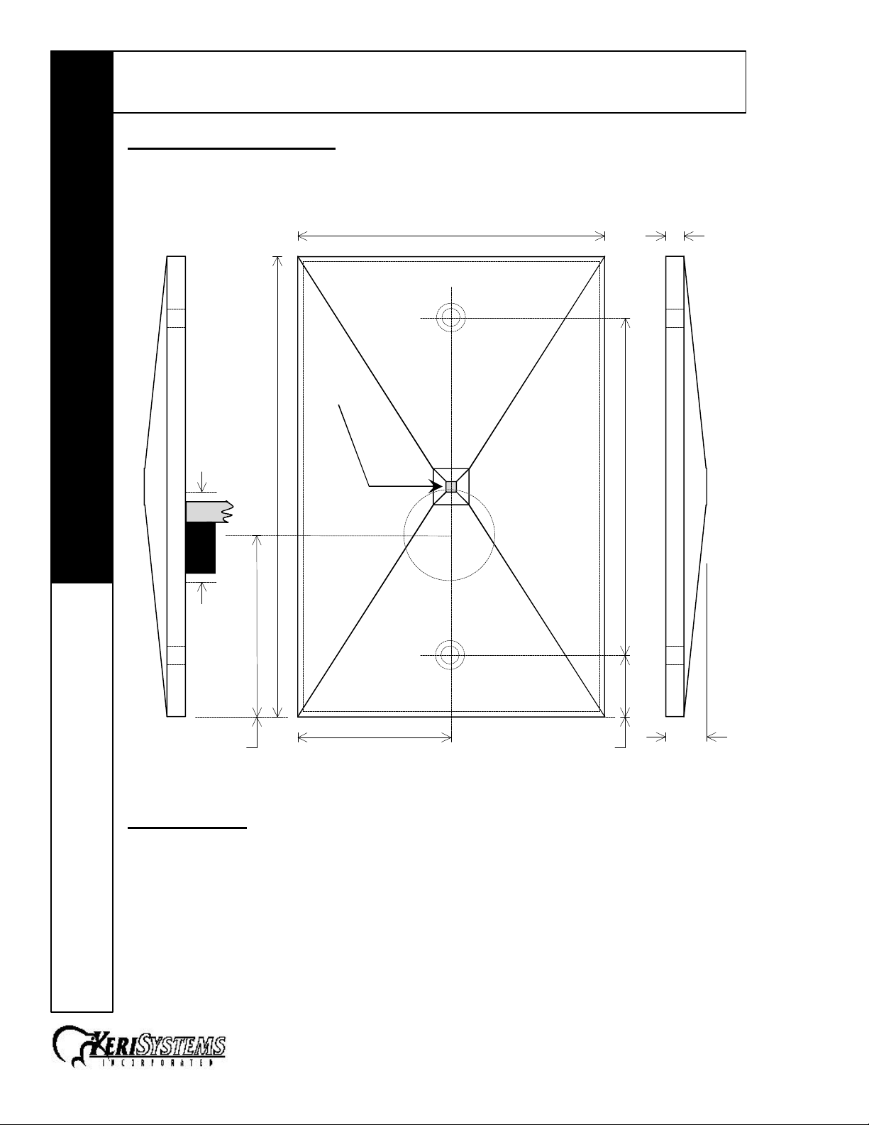
Mounting Instructions
Three holes need to be drilled to mount the P-500 Reader (see Figure 1). One large hole (7/8")
accommodates the beeper and the reader cable. Two small holes (for a #6 screw) are for
mounting the electronics package on the mullion or doorframe.
7/8" dia
Cable &
Beeper
LED
4.50" (114 mm)
3.00" (76 mm)
0.18" (4.6 mm)
3.30" (84 mm)
Connections
There are no switches or jumpers to set. The only configuration the P-500 requires is to set the
reader for single or dual LED control line operation (explained later in this document). The P-500
Reader can be connected to virtually any access panel that meets Wiegand interface standards.
All connections are made through the reader's cable. Please consult Table 1 and Figure 2 for
wiring instructions.
1530 Old Oakland Road, Suite 100 01858-001 Rev. A
San Jose, CA 95112 USA
(800) 260-5265 (408) 451-2520 FAX (408) 441-0309 Page 2 of 4
Figure 1 – P-500 Mounting Dimensions
Page 3

P-500: Sierra Reader
Quick Start Guide
P-500
Wire Color Function
Green Data 0
Blue Beeper
Red Reader Power
Black Reader Ground
Brown Second LED Control Line (Green LED)
Orange Single LED Control Line (Red LED)
White Data 1
Table 1 – Wiring Connections Figure 2 – Wiring Connections
Green - Data 0
Blue - Beeper
Red - Power
Black - Ground
Brown - Second LED
Orange - Single LED
White - Data 1
Installation Verification
The following information applies to an installation with an access panel. The access panel
controls the actions of the P-500’s LED and beeper.
Power
The P-500 is powered by the access panel, so the reader is powered on when the access panel
is powered on.
Read Range
To verify the P-500’s read range, hold a Keri Systems Wiegand card or tag parallel to the reader,
about 1 foot away and slowly bring the Card/Tag in toward the reader. Note the distance when
the reader recognizes the card (the reader beeps and the LED flashes). The reader's range will
be up to 7 inches (if mounted off a metal surface) or up to 3 inches (if mounted on a metal
surface) depending upon the installation conditions, the material on which the reader is mounted,
and whether it is a card or a tag being read. Due to the physical size difference between cards
and tags, cards provide approximately 50% greater read range than tags.
Refer to the Troubleshooting the Reader Installation section if the reader is not functioning
properly.
Switching Between Single or Dual LED Control Line Modes
The P-500 can work with control panels configured to drive either Wiegand single or dual LED
control line devices. The reader uses a “control” card to switch between single and dual line LED
control modes. The Control Line card must be ordered separately from the supplier. The default
setting for the P-500 reader is for dual LED control line operation.
To toggle between modes, simply present the LED Mode control card to the reader. The reader
will beep and the LED will flash indicating the control card was recognized and the mode has
been changed, but no data is sent to the access panel.
Troubleshooting the Reader Installation
Problem Probable Cause Corrective Action
The reader does
not recognize a
card/tag (no beep,
no LED flash).
1. One or more of the
reader's wiring
connections are
incorrect.
– continued next page –
• Power down the controller and verify
the wiring connections are correct for
the reader/access panel combination
per the instructions provided in the
Connections section on page 2.
1530 Old Oakland Road, Suite 100 01858-001 Rev. A
San Jose, CA 95112 USA
(800) 260-5265 (408) 451-2520 FAX (408) 441-0309 Page 3 of 4
Page 4

P-500: Sierra Reader
Quick Start Guide
P-500
Problem Probable Cause Corrective Action
The reader has a
short read range.
2. The reader is not
receiving proper
power from the access
panel.
3. The reader is mounted
too close to a device
that radiates
electromagnetic
interference.
1. The access panel is
not properly grounded.
2. The shield wire for the
reader's cable has
opened somewhere
between the reader
and the access panel.
3. The reader is mounted
too close to a device
that radiates
electromagnetic
interference.
4. The power supply is
generating
electromagnetic
interference.
• Verify the voltage supplied to the reader
is between 5 and 14 VDC.
• Devices such as computer monitors
radiate electromagnetic interference
that affects read range. When possible,
relocate either the reader or the device
to provide a greater distance between
the two.
• Ensure there is a quality earth ground
connection made to the access panel.
Refer to the access panel’s
documentation for specific information
regarding the earth ground connection.
• Verify the shield line from the access
panel to the reader is one continuous,
connected line. Refer to the access
panel’s installation documentation and
verify the shield line is correctly
connected to the access panel.
• Devices such as computer monitors
radiate electromagnetic interference
that affects read range. When possible,
relocate either the reader or the device
to provide a greater distance between
the two.
• The power supply on the alarm panel
should be a regulated linear supply – do
not use switching supplies as they are
often sources of electromagnetic
interference.
Data Line Level Test
The P-500 has an internal data line level test to verify the reader is able to communicate with the
access panel. A “control” card is used to trigger the data line level test. Present the card to the
reader. The reader beeps and the LED flashes to indicate the card has been read and the test
has begun. In this test the reader toggles the Wiegand data lines between high and low states –
+5 VDC to 0 VDC. This toggling occurs at a slow rate so that it can be viewed on a DVM.
1. Set the DVM to a range that can safely view +5 VDC.
2. Disconnect the Wiegand Data lines from the access panel.
3. At the access panel, connect the negative lead of the DVM to access panel ground.
4. Connect the positive lead of the DVM to the Wiegand Data 0 line.
5. Monitor the DVM. If the reader is operating correctly, the DVM will toggle between +5
VDC and 0 VDC.
6. Now connect the positive lead of the DVM to the Wiegand Data 1 line.
7. Again monitor the DVM. If the reader is operating correctly, the DVM will toggle between
+5 VDC and 0 VDC.
8. Reconnect the Wiegand Data lines to the access panel.
1530 Old Oakland Road, Suite 100 01858-001 Rev. A
San Jose, CA 95112 USA
(800) 260-5265 (408) 451-2520 FAX (408) 441-0309 Page 4 of 4
 Loading...