

Page 1
2355 MIRA MAR AVE. LONG BEACH, CA 90815-1755, (562) 986-9105 FAX (562) 986-9205
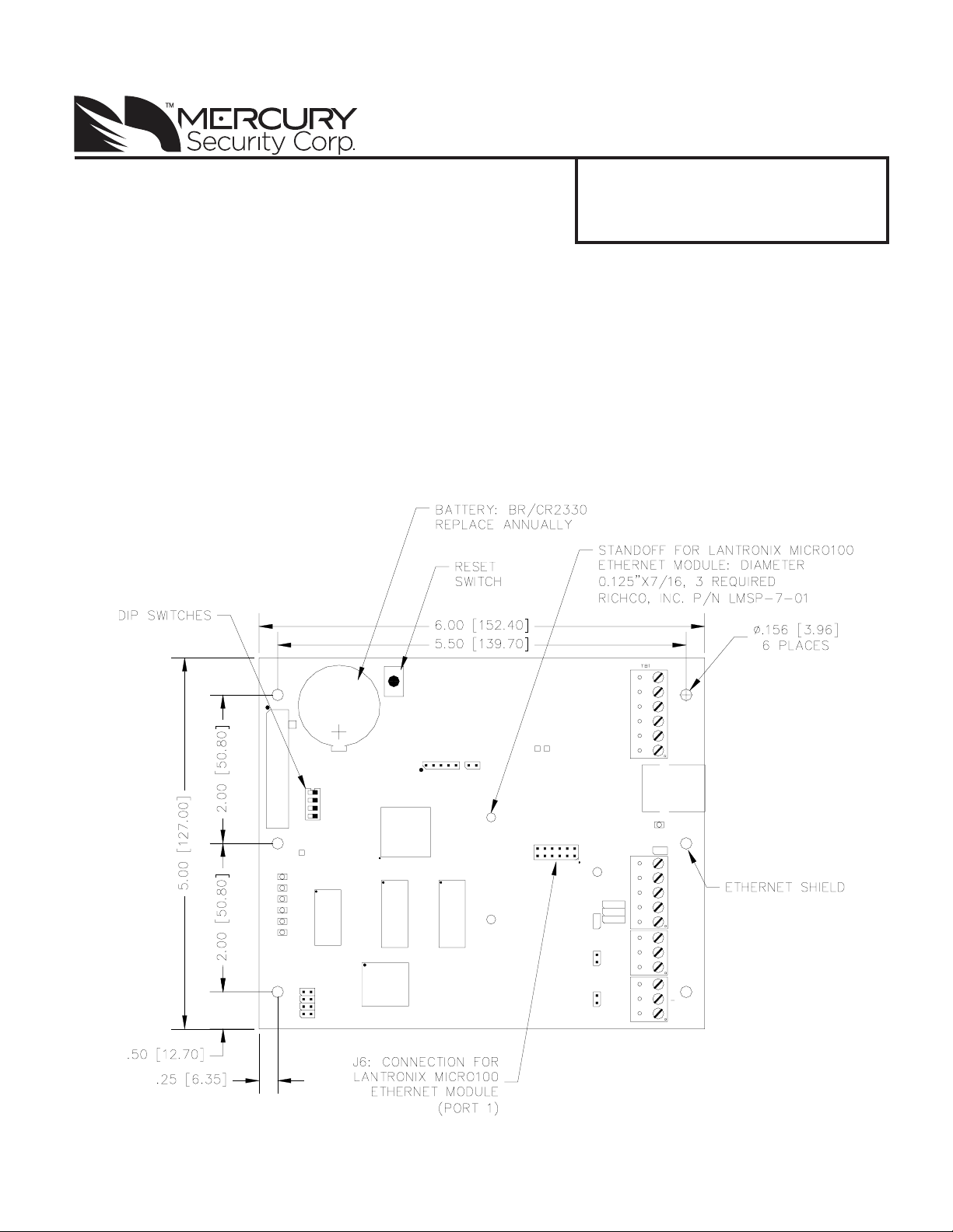
EP2500 Intelligent Controller
Installation and S pecifications:
1. General:
The EP2500 intelligent controller provides decision making, event reporting, and database storage for
the Mercury hardware platform.
It communicates with the host via on-board 10-BaseT/100Base-TX Ethernet port or port 1. Port 1 may
be set up as RS-232, 2-wire RS-485 or an optional 10-BaseT/100Base-TX using a Lantronix Micro100
interface daughter board. Subcontrollers are connected via ports 2 and 3 using 2-wire RS-485.
It is recommended that the EP2500 be mounted .25" above any conductive surface.
2. Setting Up the EP2500 Hardware:
www.mercury-security.com
This device complies with part 15 of the FCC Rules.
Operation is subject to the following two conditions: (1)
This device may not cause harmful interference, and (2)
this device must accept any interference received, including interference that may cause undesired operation.
1
2
3
4
5
6
3V BR/CR2330
J3
J12
VBAT
U7
+
-
J14
J15
J16
J17
S2
BT1
3.3V
J1 J13
1
2
3
4
S1
U1
U4U3
U5
5V
J6
485J7232
J10
J4
J5
VIN
GND
TMP
GND
FLT
GND
ACT
SPD
J1
LNK
J11
TB2
TXD
TR+
RXD
TR-
RTS
PORT 1
CTS
J9J8
GND
TR+
TR-
PORT 2
GND
TR+
PORT 3
TR-
GND
Information subject to change without notice.
Mercury Security Corporation, Copyright 2011 EP2500 DOC 10107-0030 REV: 1.03 Page 1
Page 2

Jumpers:
The EP2500 processor hardware interface is configured using jumpers to setup the port interface and
end of line termination.
JUMPERS SET AT DESCRIPT ION
J2 N/A Fac tory us e only
J3 N/A Fac tory us e only
J4 OFF Port 2 RS-485 EOL Terminator is off
ON Port 2 RS-485 E OL Terminator is on
J5 OFF Port 3 RS-485 EOL Terminator is off
ON Port 3 RS-485 E OL Terminator is on
J6 N/A Lantronix Micro100 connect i on - P ort 1
J7, J8, J9 232 Port 1 is RS-232
485 Port 1 is RS-485
J10 OFF Port 1 RS-485 EOL Terminator is off
ON Port 1 RS-485 E OL Terminator is on
J11 N/A F act ory us e on l y
J12 N/A F act ory us e on l y
J13 N/A F act ory us e on l y
J14 N/A Remote s t at us LED # 1, see note 1
J15 N/A Remote s t at us LED # 2, see note 1
J16 N/A Remote s t at us LED # 3, see note 1
J17 N/A Remote s t at us LED # 4, see note 1
NOTE 1: Observe polarity connection to LED. External current limiting is not required.
NOTE 2: Jumpers J7, J8, J9, and J10 to do not effect the operation of the Lantronix unit.
DIP Switches:
The four switches on S1 DIP switch configure the operating mode of the EP2500 processor . DIP
switches are read on power-up except where noted. Pressing switch S2 causes the EP2500 to reset.
1 2 3 4 Definitions
OFF OFF X OFF Normal operating mode
ON X X X
OFF ON X OFF Use factory default communication parameters.
ON ON X OFF
X X ON X Disabl e TLS secure link . S witch is read only when logging on.
After ini t ial i z ation, enable default User Name (admin) and Password
(pass word). The swit c h i s read on the fly, no need to re-boot.
Use OE M default c om m uni c ation parameters . Cont ac t syst em
manufact ure for details . See Bulk Eras e below.
All other switch settings are unassigned and are reserved for future use.
Factory Default Communication Parameters:
Network: static IP address = 192.168.0.251
Communication address: 0
Primary Host port: IP server , no encryption, port 3001.
Alternate Host port: RS-232, 38400 baud, no encryption, no flow control.
Information subject to change without notice.
Mercury Security Corporation, Copyright 2011 EP2500 DOC 10107-0030 REV: 1.03 Page 2
Page 3

Bulk Erase Configuration Memory:
Use the bulk erase function to erase all configuration and cardholder databases. When power is applied
with S1 switches set to 1 & 2 ON and 3 & 4 OFF, there is a 10-second window that if switch 1 or 2 is
changed to the OFF position, memory is erased. The LEDs flash the following pattern when in the reset
window:LED 1 & 2 and LED 3 & 4 flash alternately at .5 second rate. When erasing memory , LED 2
flashes at a 2 seconds rate. DO NOT CYCLE POWER. Erasing memory takes approximately 60
seconds. LEDs1 and 4 flash for 10 seconds after the memory has been erased, then the EP2500 will reboot.
3. Input Power , Cabinet Tamper and UPS Fault Input Wiring:
The EP2500 requires 12-24Vdc power. Locate power source as close to
the unit as possible. Connect power with minimum of 18 AWG wire.
Connect the GND signal to earth ground in ONE LOCA TION within
the System! Multiple earth ground connections may cause ground
loop problems and is not advised.
Observe POLARITY on 12-24Vdc input!
There are two dedicated inputs for cabinet tamper and UPS fault monitoring. Normal (safe) condition is a closed contact. If these inputs are
not used, install a jumper wire.
4. Communication Wiring:
The EP2500 processor communicates to the host via: on-board Ethernet 10-BaseT/100Base-TX port or
on port 1. Port 1 may be configured as RS-232, 2-wire RS-485 or optional Lantronix Ethernet 10BaseT/100Base-TX Micro100 interface. RS-232 interface is for direct one to one connection to a host
computer port, or a modem.
Ports 2 and 3 utilize 2-wire RS-485 interface. The interface allows multi-drop communication on a
single bus of up to 4,000 feet (1,200 m). Use twisted pair (minimum 24 AWG) with shield for the
communication with 120 ohm impedance. Install termination jumpers only on the units at each end of
the communication line.
TB1
VIN
TMP
GND
FLT
GND
+
-
GND
12 TO 24Vdc
CABINET
TAMPER
POWER
FAULT
TXD/TR1+
RXD/TR1-
RTS
CTS
GND
PORT 1 CONFIGURED
as RS-232
TXD/TR1+
RXD/TR1-
RTS
CTS
GND
PORT 1 CONFIGURE D
as 2-WIRE RS-485
TR2+
TR2-
GND
TR3+
TR3GND
PORT 2
2-WIRE RS-485
2-WIRE RS-485
5. Memory Backup Battery:
The static RAM and the real time clock device are powered by a lithium battery when input power is
removed. This battery should be replaced annually . If the data in the st atic RAM is determined to be
corrupt after power up, all data, including flash memory , is considered invalid and is erased. All
configuration data must be re-downloaded. Battery type: BR2325, BR2330, or CR2330.
Information subject to change without notice.
Mercury Security Corporation, Copyright 2011 EP2500 DOC 10107-0030 REV: 1.03 Page 3
TR2+
TR2-
GND
TR3+
TR3GND
PORT 3
Page 4

6. Status LEDs:
Power-up: All LED's OFF.
Initialization: LED's 1 through 6 are sequenced during initialization. LED's 1, 3, and 5 are turned ON
for approximately 4 seconds after the hardware initialization has completed, then the application code is
initialized. The amount of time the application takes to initialize depends on the size of the database,
about 3 seconds without a card database. Each 10,000 cards will add about 3 seconds to the applica
tion initialization. When LED's 1 through 4 flash at the same time, data is being read from or written to
flash memory , do not cycle power when in this state. If the sequence stops or repeat s, perform one of
the steps below .
1. Power-up and tag database as invalid:
Remove input power to the EP2500, place an insulator under the battery clip, wait 5-10
seconds, remove insulator, reapply input power .
2. Power-up without loading database into RAM:
Remove input power to the EP2500, set DIP to a default mode (in a default mode, the database
is not loaded into RAM), reapply input power.
3. Erase all of the configuration and databases (also erases card database for security reasons):
See procedure in DIP switch note in section 2.
If clearing the memory does not correct the initialization problem, contact technical support.
Running:
LED DES CRIPTION
1 Off-Line / On-Line and Battery S t at us
Off-Line = 20% O N, On-Line = 80% ON
Double Flash if Battery is Low
2 Host Communi c ation Ac tivit y (E t hernet or S erial P ort 1)
3 Port 2 Communi cat i on Ac t ivi ty
4 Port 3 Communi cat i on Ac t ivi ty
5 Una ssigned
6 Una ssigned
D7 Host Com muni c ation (Et hernet P ort 0)
YEL On-board Ethernet Speed: OFF = 10Mb/S, ON = 100Mb/S (Yellow LED)
GRN OF F = No Link , ON = Good Link (Green LED), Fl as hi ng = E thernet Activity
7. Specifications:
** The processor is for use in low voltage, class 2 circuits only.
Primary power: 12 to 24Vdc ±10%, 300mA maximum
Memory and
Clock Backup: 3 Volt Lithium, type BR2325, BR2330, CR2330
12Vdc @ 240mA (325mA with Micro100) nominal
24Vdc @ 135mA (175mA with Micro100) nominal
Ports:
Port 1 RS-232 or 2-wire RS-485: 9,600 to 1 15,200 bps, async
Port 2 & 3 2-wire RS-485: 2,400 to 38,400 bps, async
Inputs: 2 non-supervised, dedicated for cabinet tamper and power fault monitoring
Information subject to change without notice.
Mercury Security Corporation, Copyright 2011 EP2500 DOC 10107-0030 REV: 1.03 Page 4
Page 5

Cable requirements:
Environmental:
Mechanical:
Lantronix NIC support: Standoff size - Diameter .125 inch x 7/16 inch long
Specification subject to change without notice.
Warranty
Power: 1 twisted pair, 18 AWG
RS-485: 24 AWG, 4,000ft (1,200m) maximum, twisted pair with shield. 120 Ohm
RS-232: 24 AWG, 25ft (7.6m) maximum
Ethernet: Cat 5
Alarm input: 1 twisted p air , 30 ohms maximum
T emperature: 0 to 70°C, operating
-55 to +85°C, storage
Humidity: 0 to 95% RHNC
Dimension: 5 in. (127mm) W x 6 in. (152.4mm) L x 1 in. (25mm) H
Weight: 4.1 oz ( 1 15 gm) nominal
Richco, Inc. part number LMSP-7-01, 3 pieces (Not supplied)
Mercury Security Corporation warrants the product is free from defects in material and workmanship under normal use and service with proper
maintenance for one year from the date of factory shipment. Mercury Security Corporation assumes no responsibility for products damaged by
improper handling or installation. This warranty is limited to the repair or replacement of the defective unit.
There are no expressed warranties other than set forth herein. Mercury Security Corporation does not make, nor intends, nor does it authorize
any agent or representative to make any other warranties, or implied warranties, and expressly excludes and disclaims all implied warranties of
merchantability or fitness for a particular purpose.
Returned units are repaired or replaced from a stock of reconditioned units. Returns must be accompanied by a return authorization number (RMA)
obtained from customer service, and prepaid postage and insurance.
Liability
The Interface should only be used to control exits from areas where an alternative method for exit is available. This product is not intended for,
nor is rated for operation in life-critical control applications. Mercury Security Corporation is not liable under any circumstances for loss or damage
caused by or partially caused by the misapplication or malfunction of the product. Mercury Security Corporation's liability does not extend beyond
the purchase price of the product.
Information subject to change without notice.
Mercury Security Corporation, Copyright 2011 EP2500 DOC 10107-0030 REV: 1.03 Page 5
 Loading...