

Page 1
www.mercury-security.com
2355 MIRA MAR AVE. LONG BEACH, CA 90815-1755, (562)986-9105 FAX (562) 986-9205
This device complies with part 15 of the FCC Rules.
Operation is subject to the following two conditions: (1) This
device may not cause harmful interference, and (2) this
device must accept any interference received, including
interference that may cause undesired operation.
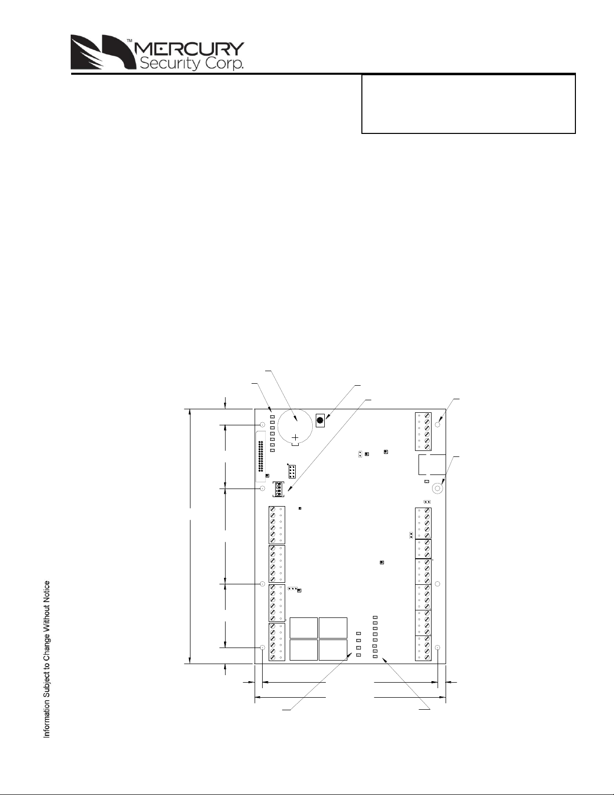
EP1502 Intelligent Controller
J4
J3
1
2
3
TMP
FLT
R1
R2
+
1
3
2
4
J8
RESET
S2
BT1
3V BR/CR2330
J1
5V
3.3V
2
3
4
1
S1
VBAT
IN1
K
1
K
2
K
3
K
4
K2 K1
K3K4
IN2
IN3
IN4
IN5
IN6
IN7
IN8
8V
J6
J2
J5
J7
PASS
12V
GND
DAT
D0
TB8
READER 1
BZR
VO
GND
FLT
GND
TMP
GND
VIN
TB1
LED
D1
CLK
READER 2
D1
LED
VO
BZR
GND
CLK
D0
DAT
TB9
NO
OUT 1 C
NC
NO
OUT 2 C
NC
NC
OUT 4 C
NC
NO
NO
OUT 3 C
TB10TB11
RXD
CTS
GND
RTS
TXD
TB2
TB3
TR+
GND
TR-
IN1
IN2
IN3
IN4
IN5
IN6
IN7
IN8
TB4
TB5
TB6
TB7
.25 [6.35] 5.50 [139.70] .25 [6.35]
6.00 [152.40]
.50 [12.70]
2.00 [50.80]
3.00 [76.20]
2.00 [50.80]
.50 [12.70]
8.00 [203.20]
Ø.156 [3.96]
8 PLACES
RESET SWITCH
BATTERY: BR/CR2330
REPLACE ANNUALLY
-
STATUS LED's
DIP SWITCHES
RELAY
STATUS
LED's
INPUT
STATUS
LED's
ETHERNET
SHIELD
with Two Reader Interface
Installation and Specifications:
1. General
The EP1502 intelligent controller provides decision making, event reporting, and database storage for the
Mercury hardware platform. Two reader interfaces provide control for two doors.
It communicates with the host via on-board 10-BaseT/100Base-TX Ethernet port. Alternatively, port 1
(RS-232) can be used for host communication.
Two physical barriers can be controlled with the EP1502. Each reader port can accommodate a readhead that utilizes Wiegand, magnetic stripe, or 2-wire RS-485 electrical signaling standards, one or two
wire LED controls, and buzzer control (one wire LED mode only). Four Form-C relay outputs may be
used for strike control or alarm signaling. The relay contacts are rated at 5 A @ 30 Vdc, dry contact
configuration. Eight inputs are provided for monitoring the door contacts, exit push buttons and alarm
contacts. The EP1502 requires 12-24 Vdc for power. It is recommended that the EP1502 be mounted
.25" minimum above any conductive surface.
2. EP1502 Hardware:
Mercury Security Corporation © 2011 EP1502 DOC 10107-0031 REV 1.05 Page 1
Page 2

CONNECTION
CONNECTION
TB8
Reader 1
GND: Ground
TB1
Power Input
VIN: 12 to 24 Vdc
DAT/D0: Data/Data 0/TR-
GND
CLK/D1: Clock/Data 1/TR+
Cabinet
TMP
BZR: Reader Buzzer
Tamper Input
GND
LED: Reader LED
Power Fault
FLT
VO: Reader Power
Input
GND
TB9
Reader 2
GND: Ground
TB2
Host Port 1
TXD (RS-232)
DAT/D0: Data/Data 0/TR-
RXD (RS-232)
CLK/D1: Clock/Data 1/TR+
RTS (RS-232)
BZR: Reader Buzzer
CTS (RS-232)
LED: Reader LED
GND (RS-232)
VO: Reader Power
TB3
SIO Port
TR+ (2-wire RS-485)
TB10
Out 1
NO: Normally Open Contact
TR- (2-wire RS-485)
C: Common
GND (2-wire RS-485)
NC: Normally Closed Contact
TB4
Input 1
IN1
Out 2
NO: Normally Open Contact
IN1
C: Common
Input 2
IN2
NC: Normally Closed Contact
IN2
TB11
Out 3
NO: Normally Open Contact
TB5
Input 3
IN3
C: Common
IN3
NC: Normally Closed Contact
Input 4
IN4
Out 4
NO: Normally Open Contact
IN4
C: Common
TB6
Input 5
IN5
NC: Normally Closed Contact
IN5
Input 6
IN6
IN6
TB7
Input 7
IN7
IN7
Input 8
IN8
IN8
JUMPERS
SET AT
DESCRIPTION
J1
N/A
Factory Use Only
J2
N/A
10Base-T/100Base-Tx Ethernet Connection (Port 0)
J3
N/A
Factory Use Only
J4
N/A
Factory Use Only
J5
OFF
Port 2 RS-485 EOL Terminator is Off
ON
Port 2 RS-485 EOL Terminator is On
J6
N/A
Factory Use Only
J7
Reader Power Select. See Note 1
12V
12 Vdc at Reader Ports
PASS
VIN "Pass Through" to Reader Ports
J8-1
N/A
Remote Status Led #1. See Note 2
J8-2
N/A
Remote Status Led #2. See Note 2
J8-3
N/A
Remote Status Led #3. See Note 2
J8-4
N/A
Remote Status Led #4. See Note 2
3. EP1502 Wiring and Setup:
Jumpers:
The EP1502 processor hardware interface is configured using jumpers to setup the port interface and end
of line termination.
Note 1: The input power (VIN) must be 20 Vdc minimum if the 12 Vdc selection is to be used.
Note 2: Observe POLARITY connection to LED. External current limiting is not required.
Mercury Security Corporation © 2011 EP1502 DOC 10107-0031 REV 1.05 Page 2
Page 3

1 2 3
4
Definitions
OFF
OFF
X
OFF
Normal operating mode.
ON X X
X
After initialization, enable default User Name (admin) and Password
(password). The switch is read on the fly, no need to re-boot.
OFF
ON
X
OFF
Use factory default communication parameters.
ON
ON
X
OFF
Use OEM default communication parameters. Contact system
manufacture for details. See Bulk Erase below.
X X ON
X
Disable TLS secure link. Switch is read only when logging on.
ON
ON
OFF
OFF
Bulk Erase prompt mode at power up. See Bulk Erase below.
12 TO 24Vdc
GND
VIN
+
-
CABINET
TAMPER
POWER
FAULT
TB1
TMP
GND
FLT
GND
DIP Switches:
The four switches on S1 DIP switch configure the operating mode of the EP1502 processor.
DIP switches are read on power-up except where noted. Pressing switch S2 causes the EP1502 to reset.
All other switch settings for unassigned and are reserved for future use. X = don’t care.
In the factory or OEM default modes, downloaded configuration/database is not saved to flash memory.
Factory Default Communication Parameters:
Network: static IP address: 192.168.0.251
Communication address: 0
Primary Host port: IP server, no encryption, port 3001.
Alternate Host Port 1: RS-232, 38,400 baud, no encryption, no flow control.
Bulk Erase Configuration Memory:
The bulk erase function can be used for the following purposes:
To erase all configuration and cardholder database data.
To recover from a corrupted database in the unlikely event the database gets corrupted and causes
the EP1502 to continuously reboot.
When power is applied with S1 switches set to 1 & 2 ON and 3 & 4 OFF, there is a 10-second window
that if switch 1 or 2 is changed to the OFF position memory is erased. The LEDs flash the following
pattern when in the reset window: LED 1 & 2 and LED 3 & 4 flash alternately at .5 second rate. When
erasing memory, LED 2 flashes at a 2 second rate;
seconds to erase the memory. LEDs 1 and 4 flash for 10 seconds after the memory has been erased,
then the EP1502 will re-boot.
DO NOT CYCLE POWER
. It takes less than 60
4. Input Power, Cabinet Tamper and UPS Fault Input Wiring:
The EP1502 requires 12-24 Vdc power. Locate power source as
close to the unit as possible. Connect power with minimum of 18
AWG wire.
LOCATION within the system! Multiple earth ground connections
may cause ground loop problems and is not advised.
Observe POLARITY on 12-24 Vdc input!
There are two dedicated inputs for cabinet tamper and UPS fault
monitoring. Normal (safe) condition is a closed contact. If these
inputs are not used, install a jumper wire.
Connect the GND signal to earth ground in ONE
5. Communication Wiring:
The EP1502 controller communicates to the host via the on-board 10-BaseT/100Base-TX Ethernet
interface (port 0) and/or RS-232 interface (port 1). RS-232 interface is for direct one to one connection to
a host computer port or via modem, 25 feet maximum.
The serial I/O device communication port (TB3) is a 2-wire RS-485 interface which can be used to
connect additional I/O panels. The interface allows multi-drop communication on a single bus of up to
4,000 feet (1,219 m). Use twisted pairs (minimum 24 AWG) with an overall shield for communication.
Mercury Security Corporation © 2011 EP1502 DOC 10107-0031 REV 1.05 Page 3
Page 4

DATA1/DATA0 - CLOCK/DATA
2-WIRE RS-485
RXD
TXD
RTS
CTS
GND
Port 1, RS-232 To Host
TR-
TR+
GND
To serial I/O Devices
TB2
TB3
BLK (6)
ORG (5)
BRN (4)
GRN (2)
RED (1)
WHT (3)
GND
DAT/D0
CLK/D1
BZR
LED
VO
MR-10/20 READER
TB8 OR TB9
ADDRESS 0
MR-DT
RS-485 MODE
9600 BAUD
READER PORT
2-WIRE RS-485
12Vdc (RED) (1)
TR+ (BLUE) (3)
TR- (GRAY) (4)
GROUND (BLACK) (2)
GND
DAT/D0
CLK/D1
VO
TB8 OR TB9
Communication Wiring (continued):
IMPORTANT NOTE! Install the termination jumper ONLY on the panel at each end of the RS-485
bus. Failure to do so will compromise the proper operation of the communication channel!
6. Reader Wiring:
Each reader port supports Wiegand, magnetic stripe, and 2-wire RS-485 electrical interfaces. Power
to the reader is selectable: 12 Vdc (VIN must be greater than 20 Vdc), or power is passed-through
(PT) from the input voltage of the EP1502 (TB1-VIN) and is current limited to 150 mA for each reader
port. Readers that require different voltage or have high current requirements should be powered
separately. Refer to the reader manufacture specifications for cabling requirements. In the 2-wire
LED mode the Buzzer output in used to drive the second LED. Reader port configuration is set via
the host software.
7. Input Circuit Wiring:
Mercury Security Corporation © 2011 EP1502 DOC 10107-0031 REV 1.05 Page 4
Typically, these inputs are used to monitor door position, request to exit, or alarm contacts. Input circuits
can be configured as unsupervised or supervised. When unsupervised, reporting consists of only the
open or closed states. When configured as supervised, the input circuit will report not only open and
closed, but also open circuit, shorted, grounded*, and foreign voltage*. A supervised input circuit requires
two resistors be added to the circuit to facilitate proper reporting. The standard supervised circuit
requires 1k Ohm, 1% resistors and should be located as close to the sensor as possible. Custom end of
line (EOL) resistances may be configured via the host software.
* Grounded and foreign voltage states are not a requirement of UL 294 and therefore not verified by UL.
Page 5

1K,1%
1K,1%
1K,1%
1K,1%
Standard Supervised Circuit,
Normally Closed Contact
Standard Supervised Circuit,
Normally Open Contact
Unsupervised Circuit,
Normally Open Contact
Unsupervised Circuit,
Normally Closed Contact
Terminal Blocks
TB4 Through TB7
Diode Selection:
Diode current rating: 1x strike count
Diode breakdown voltage: 4x strike voltage
For 12 Vdc or 24 Vdc strike, diode 1N4002
(100V/1A) typical.
MOV Selection:
Clamp voltage: 1.5x Vac RMS.
For 24 Vac strike, Panasonic:
ERZ-C07DK470 typical
Input Circuit Wiring (continued):
The input circuit wiring configurations shown are supported but may not be typical:
8. Relay Circuit Wiring:
Four relays with Form-C contacts are provided for controlling door lock mechanisms or alarm signaling.
The relay contacts are rated at 5 A @ 30 Vdc, dry contact configuration. Each relay has a Common pole
(C), a Normally Open pole (NO) and a Normally Closed pole (NC). When you are controlling the delivery
of power to the door strike, the Normally Open and Common poles are used. When momentarily
removing power to unlock the door, as with a mag lock, the Normally Closed and Common poles are
used. Check with local building codes for proper egress door installation.
Door lock mechanisms can generate feedback to the relay circuit that can cause damage and premature
failure of the relay. For this reason, it is recommended that either a diode or MOV (metal oxide varistor)
be used to protect the relay. Wire should be of sufficient gauge to avoid voltage loss.
Mercury Security Corporation © 2011 EP1502 DOC 10107-0031 REV 1.05 Page 5
Page 6

LED
DESCRIPTION
1
Off-Line / On-Line and Battery Status
Off-Line = 20% ON, On-Line = 80% ON
Double Flash if Battery is Low
2
Host Communication Activity (Ethernet or Serial Port 1)
3
Internal SIO Communication Activity
TMP
External SIO Communication Activity
FLT
Unassigned
R1
Reader 1: Clock/Data or D1/D0 Mode = Flashes when Data is Received, Either
Input. RS-485 Mode = Flashes when Transmitting Data
R2
Reader 2: Clock/Data or D1/D0 Mode = Flashes when Data is Received, Either
Input. RS-485 Mode = Flashes when Transmitting Data
D16
Flashes with Host Communication (Ethernet Port 0)
YEL
Ethernet Speed: OFF = 10Mb/S, ON = 100Mb/S
GRN
OFF = No Link, ON = Good Link, Flashing = Ethernet Activity
IN1
Input IN1 Status: OFF = Inactive, ON = Active, Flash = Trouble. See Note 1.
IN2
Input IN2 Status: OFF = Inactive, ON = Active, Flash = Trouble. See Note 1.
IN3
Input IN3 Status: OFF = Inactive, ON = Active, Flash = Trouble. See Note 1.
IN4
Input IN4 Status: OFF = Inactive, ON = Active, Flash = Trouble. See Note 1.
IN5
Input IN5 Status: OFF = Inactive, ON = Active, Flash = Trouble. See Note 1.
IN6
Input IN6 Status: OFF = Inactive, ON = Active, Flash = Trouble. See Note 1.
IN7
Input IN7 Status: OFF = Inactive, ON = Active, Flash = Trouble. See Note 1.
IN8
Input IN8 Status: OFF = Inactive, ON = Active, Flash = Trouble. See Note 1.
K1
Relay K1: ON = Energized
K2
Relay K2: ON = Energized
K3
Relay K3: ON = Energized
K4
Relay K4: ON = Energized
9. Memory and Real Time Clock Backup Battery:
The static RAM and the real time clock are backed up by a lithium battery when input power is removed.
This battery should be replaced annually. If data in the static RAM is determined to be corrupt after
power up, all data, including flash memory, is considered invalid and is erased All configuration data
must be re-downloaded. Remove the insulator from the battery holder after installation. Battery type:
BR2325, BR2330, or CR2330.
10. Status LEDs:
Power-up: All LED's OFF.
Initialization: LED's 1, 2, 3, TMP, FLT, R1, R2, IN1, IN2, IN3, IN4, IN5, IN6, IN7 and IN8 are sequenced
during initialization. LED's 1, 3, and TMP are turned ON for approximately 4 seconds after the hardware
initialization has completed, then the application code is initialized. The amount of time the application
takes to initialize depends on the size of the database, about 3 seconds without a card database. Each
10,000 cards will add about 3 seconds to the application initialization. When LED's 1, 2, 3 and TMP flash
at the same time, data is being read from or written to flash memory, do not cycle power when in this
state.
Running: After initialization is complete, the LEDs have the following meanings: At power up, LEDs 2
through 6 are turned ON then OFF in sequence.
Note 1: If this input is defined, every three seconds the LED is pulsed to its opposite state for 0.1
seconds, otherwise, the LED is off.
Mercury Security Corporation © 2011 EP1502 DOC 10107-0031 REV 1.05 Page 6
Page 7

11. Specifications:
The interface is for use in low voltage, Class 2 Circuits only.
The installation of this device must comply with all local fire and electrical codes.
Primary Power: 12-24 Vdc±10%, 500 mA maximum (reader current not included)
12 Vdc @ 250 mA (plus reader current) nominal
24 Vdc @ 150 mA (plus reader current) nominal
Memory and Clock
Backup Battery: 3 Volt Lithium, type BR2325, BR2330 or CR2330
Host Communication: Ethernet: 10BaseT/100Base-TX, and RS-232; 9,600 to 115,200 bps,
asynchronous, half-duplex, 1 start bit, 8 data bits, and 1 stop bit.
SIO Communication 2-wire RS-485, 2,400 to 115,200 bps, asynchronous, half-duplex,
1 start bit, 8 data bits, and 1 stop bit.
Inputs: Two dedicated for tamper and UPS fault monitoring.
Eight for door position monitoring, request to exit or alarm contacts.
Relays: Four each: Form-C, 5 A @ 30 Vdc, resistive.
Reader Interface:
Reader Power: 12 Vdc±10% regulated, current limited to 150 mA for each reader.
(jumper selectable) or
12 to 24 Vdc±10% (input voltage passed through) current limited to 150 mA
for each reader.
Data Inputs: TTL compatible inputs, mag stripe and Wiegand standards supported.
RS-485 Mode: 9,600 to 38,400 bps, asynchronous, half-duplex, 1 start bit, 8 data bits, and 1
LED Output: TTL levels, high>3 V, Low<0.5 V, 5 mA source/sink maximum.
Buzzer Output: TTL levels, high>3 V, Low<0.5 V, Low=Active, 5 mA source/sink maximum.
Cable requirements:
Power: 1 twisted pair, 18 AWG.
Ethernet: CAT-5, minimum.
RS-485:
(I/O Device Port): 24 AWG, 4,000 ft (1,219 m) maximum, twisted pair(s) with an overall shield.
(Reader Port): 24 AWG, 2,000 ft (609.6 m) maximum, twisted pair(s) with an overall shield.
RS-232: 24 AWG, 25 ft (7.6 m) maximum.
Alarm Input: 1 twisted pair, 30 ohms maximum, typically 22 AWG @ 1000 ft (304.8 m).
Environmental:
Temperature: 0 to 70 °C, operating, -55 to +85 °C, storage
Humidity: 10 to 95% RHNC
Mechanical:
Dimension: 8 in (203.2 mm) W x 6 in (152.4 mm) L x 1 in (25 mm) H
Maximum cable length: 500 ft (152 m).
stop bit. Maximum cable length: 2000 ft (609.6 m).
Weight: 9 oz (255 g) nominal, board only
Mercury Security Corporation © 2011 EP1502 DOC 10107-0031 REV 1.05 Page 7
Page 8

Warranty
Mercury Security Corporation warrants the product is free from defects in material and workmanship
under normal use and service with proper maintenance for one year from the date of factory shipment.
Mercury Security Corporation assumes no responsibility for products damaged by improper handling or
installation. This warranty is limited to the repair or replacement of the defective unit.
There are no expressed warranties other than set forth herein. Mercury Security Corporation does not
make, nor intends, nor does it authorize any agent or representative to make any other warranties, or
implied warranties, and expressly excludes and disclaims all implied warranties of merchantability or
fitness for a particular purpose.
Returned units are repaired or replaced from a stock of reconditioned units. Returns must be
accompanied by a return authorization number (RMA) obtained from customer service, and prepaid
postage and insurance.
Liability
The Interface should only be used to control exits from areas where an alternative method for exit is
available. This product is not intended for, nor is rated for operation in life-critical control applications.
Mercury Security Corporation is not liable under any circumstances for loss or damage caused by or
partially caused by the misapplication or malfunction of the product. Mercury Security Corporation's
liability does not extend beyond the purchase price of the product.
Mercury Security Corporation © 2011 EP1502 DOC 10107-0031 REV 1.05 Page 8
 Loading...