

Page 1
EntraGuard® Silver Walk-Up Package
Quick Start Guide
This quick start guide provides the basic information needed to mount, install, power up, and program a basic EntraGuard
Silver Walk-Up Package. The Walk-Up Package is made from an EntraGuard Silver Telephone Entry Controller and a
PXL-500G-1 controller in a single container. The Walk-Up Package comes pre-wired from the factory. The EntraGuard
Silver Walk-Up Package may be used as a stand-alone unit or in a PXL/EntraGuard Access Control network. For
additional information refer to the full set of documentation available on the Keri Installation CD or at www.kerisys.com
(instructional training is also available at the website).
All door control functions are controlled by the EntraGuard board. Door contacts (DSM) and Request to Exit
(RTE) are wired to the EntraGuard board. When a credential is presented to the reader (mounted on the front
panel of the Walk-Up unit) and access is granted, the Lock Output relay of the PXL-500G-1 will trigger the R TE of
the EntraGuard board and the EntraGuard board will trigger the EntraGuard Lock Output Relay. The
EntraGuard board will control monitoring of door position and RTE (if DSM and RTE are in use).
NOTE: It is the responsibility of the installation organization to have only technically qualified personnel performing the
installation.
Section 01 - Drawings Section 05 - Communication
Section 02 - Specifications Section 06 - Powering Up for the First Time
Section 03 - Cable Requirements Section 07 - Setup Controller
Section 04 - Earth Ground and the 12 VDC Power Section 08 - Contact Keri Systems
1.0 Drawings
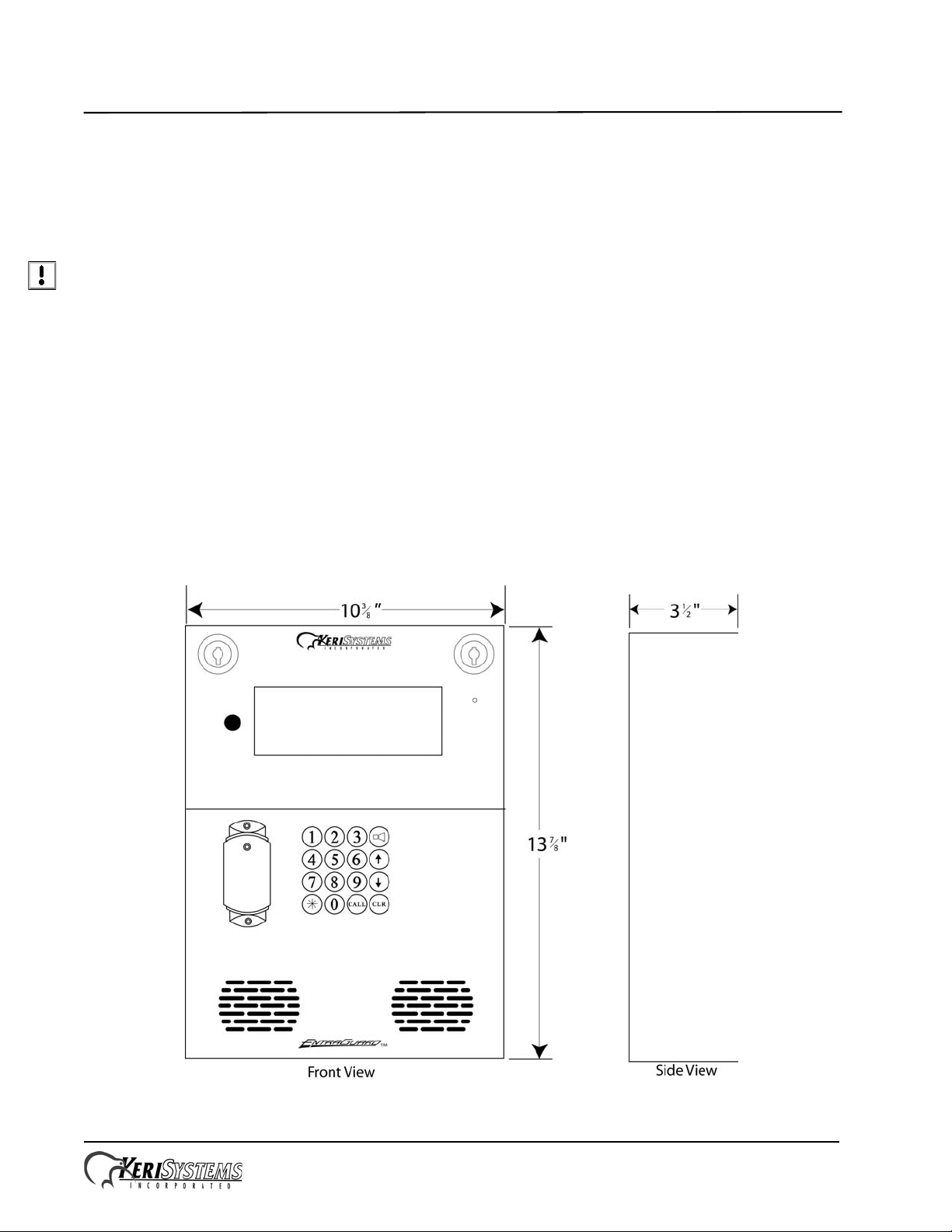
1.1 EntraGuard Silver Walk-Up Package Front Panel
Figure 1: The EntraGuard Silver Telephone Entry Controller - Front Panel
Page 1 of 12 P/N: 01535-001 Rev. A
Page 2
EntraGuard® Silver Walk-Up Package
Quick Start Guide
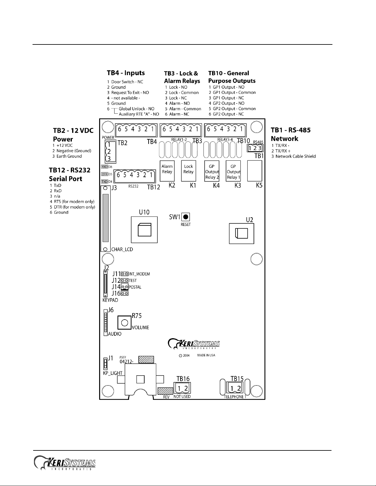
1.2 Silver Telephone Entry Controller
Figure 2: The Silver Telephone Entry Controller
NOTE: You must power down the unit before attempting to make or remove any connections. Failure to do so will
damage the controller.
Page 2 of 12 P/N: 01535-001 Rev. A
Page 3
EntraGuard® Silver Walk-Up Package
Quick Start Guide
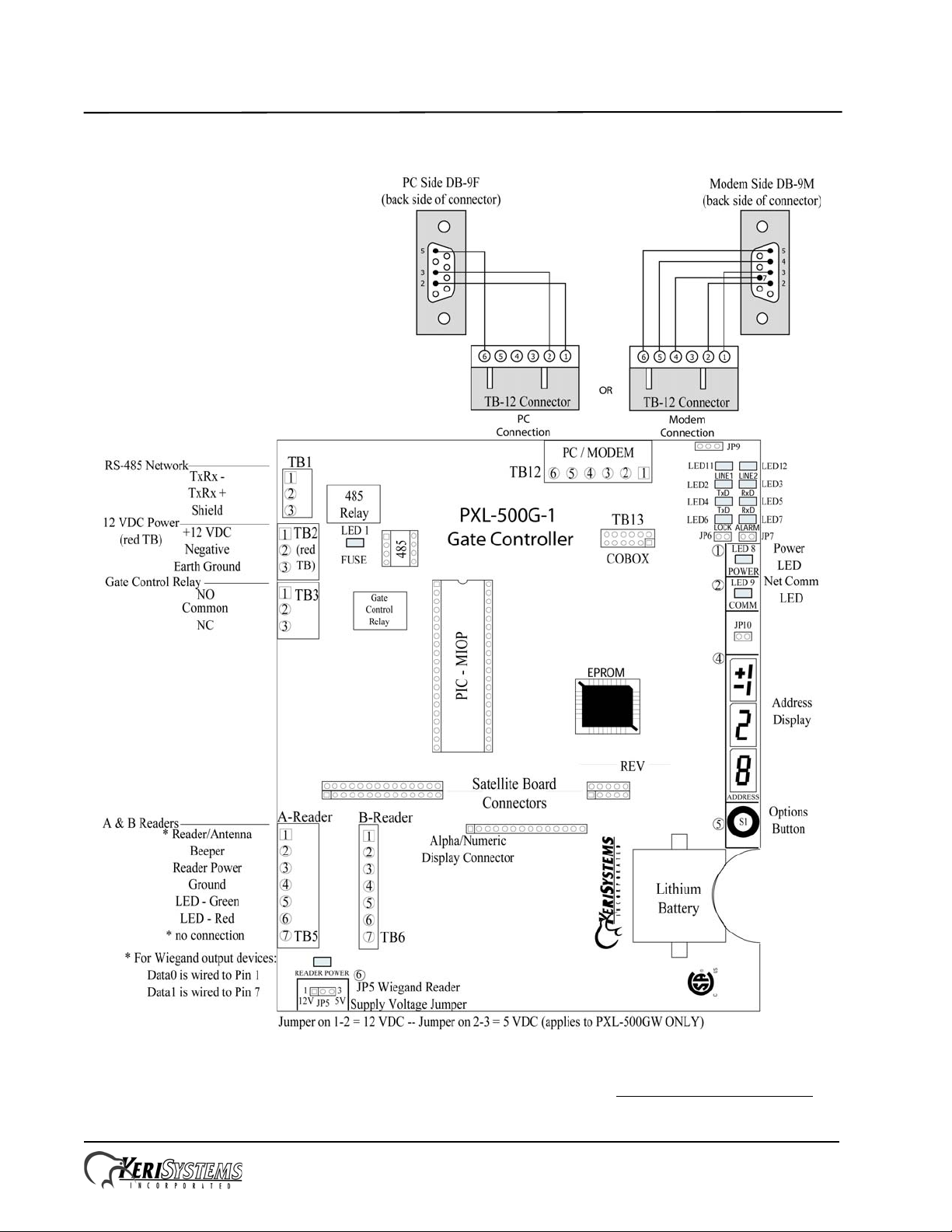
1.3 PXL-500G-1 Controller
Figure 3: The PXL-500G-1 Controller
NOTE: For information on the optional PXL-500G-1 board and gate control, see the PXL-500G-1 Quick Start Guide
(P/N 01532-001).
Page 3 of 12 P/N: 01535-001 Rev. A
Page 4
EntraGuard® Silver Walk-Up Package
Quick Start Guide
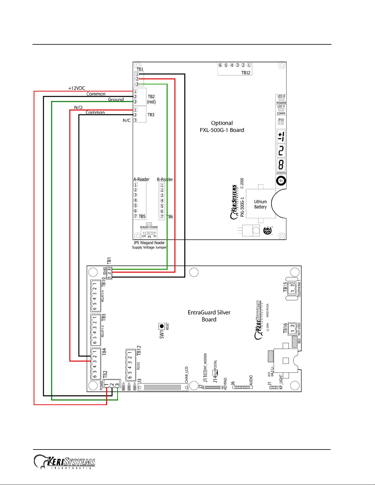
1.4 Board Placement With the PXL-500G-1 Board (Walk-Up Package)
Figure 4: EntraGuard Silver Walk-Up Package Wiring (Factory Pre-Wir ed)
Page 4 of 12 P/N: 01535-001 Rev. A
Page 5

EntraGuard® Silver Walk-Up Package
Quick Start Guide
2.0 Specifications
Unit Dimensions (nominal)
• 13
• (35 cm by 27 cm by 9 cm)
Operating Temperature/Humidity Range
• -20°F to 140°F (-29°C to 60°C)
• 0% to 90% Relative Humidity, non-condensing
Controller Power Requirements
• 12 VDC @ 1 A (Silver controller ONLY)
• 12 VDC @ 2 A (Silver with optional PXL controller)
Current Draw
• maximum current draw 750 mA for a controller
NOTE: If an electronic locking device (such as a magnetic lock, a door strike, or similar device) is to be driven by the
same power supply as the EntraGuard Silver controller, please ensure the power supply provides enough current to drive
every device connected to that supply plus an adequate safety margin. AC power cannot be used.
7
/8 inches high by 10 3/8 inches wide by 3 1/2 inches deep, including hinges
NOTE: Isolation of power supplies may be required with high transient situations.
Controller Memory Retention
• 5 year lithium battery back up to support controller RAM and real-time clock
Output Relay Contact Rating
• 1 Amp @ 24 VDC
Input Device Configuration - 4 Outputs
• Door Sense normally closed
• Request to Exit normally open
• Global Unlock normally open (on master only), or
Auxiliary RTE A-Door normally open
Users Allowed
• 750 tenants maximum
Event Storage Capacity
• 3,640 events
Page 5 of 12 P/N: 01535-001 Rev. A
Page 6

EntraGuard® Silver Walk-Up Package
Quick Start Guide
3.0 Cable Requirements
RS-232 Serial Cable
• three conductor, shielded, stranded, AWG 24 wire (Belden 9533 or a larger gauge)
• 50 foot maximum length (per RS-232 industry specification - greater lengths are not recommended)
RS-485 Network Cable
• one twisted, shielded pair of conductors, stranded, AWG 24 wire (Belden 9501 or a larger gauge)
• 4,000 foot total network length (per RS-485 industry specification)
• extended network configurations are possible – refer to the Network Wiring Application Note
extended network configurations of up to 5,000 feet per star line and 16,000 feet total network length
Telephone
• 1 pair copper phone line
NOTE: EntraGuard Silver is not to be used with a Centrex, PBX, or digital phone line. Only use a Plain Old T elephone
Service (POTS) analog phone line.
Input Power
• two conductor, stranded, AWG 18 wire (Belden 8461 or a larger gauge)
(P/N 01824-002) for
NOTE: On long power cable runs, the cable resistance causes a drop in voltage at the end of the cable run. Be sure your
power supply does provide 12 VDC at the end of the cable run.
Earth Ground
• Single conductor, AWG 18 wire (or a larger gauge)
Input and Output Connections
• two conductor, stranded, AWG 22 (or a larger gauge)
NOTE: The Lock Output relay may require a heavier gauge of wire depending upon the current demands of the lock and
the length of the lock wiring run.
NOTE: If plenum cable is required, please reference the Belden plenum equivalent to the cables listed above.
1
4.0 Earth Ground and the 12 VDC Power
The EntraGuard Silver panel requires 12 VDC power at 750 mA. Y ou must make a quality earth ground connection to the
controller prior to connecting the DC power lines. The earth ground provides protection for the controller and ensures the
best possible operating conditions. Possible sources for earth ground are a ground rod, a cold water pipe, a steel building
frame, the electrical system ground at the breaker/fuse box, or the telephone system ground. The earth ground connection
should be located as close as possible to the controller.
1. Ground wire is green, with or without yellow tracer.
Page 6 of 12 P/N: 01535-001 Rev. A
Page 7

EntraGuard® Silver Walk-Up Package
Quick Start Guide
5.0 Communication
The communication section handles three different, but related, topics:
• Communication between EntraGuard Silver controller and tenants
• Communication between the master EntraGuard Silver controller and the host computer for programming
• Communication between networked EntraGuard Silver/PXL-500/510 controllers
NOTE: Keri Systems recommends performing a bench test on each unit prior to installation to rule out any phone line
problems.
5.1 Between EntraGuard Silver Unit and Tenants
The telephone communication is done via a copper phone line to TB-15. Connect the TIP line to either Pin 1 or Pin 2 then
connect the Ring line to the other Pin.
There are three ways of connecting the phone line for communication between the EntraGuard Silver unit and the tenants.
5.1.1 Single Phone Line for a Single EntraGuard Silver Unit
For a single EntraGuard Silver unit, connect the phone line to TB-15 on the EntraGuard Silver board (see Figure 2 on
page 2).
5.1.2 Individual Phone Lines for each EntraGuard Silver Unit on a Network
The set up for individual phone lines for each EntraGuard unit is the same as for a single phone line for a single
EntraGuard Silver controller. Each phone line is connected to TB-15 on each EntraGuard Silver board.
5.1.3 Shared Phone Line for Multiple EntraGuard Silver Units on a Network
A single phone line may be shared for communication between multiple EntraGuard Silver units and tenants. The phone
line is plugged into TB-15 on the master EntraGuard Silver unit with the phone line then going out of the TB-15 phone
plug to the next unit’s TB-15 and so on to all the networked EntraGuard units.
NOTE: Sharing a phone line for multiple EntraGuard units is limited to a maximum of 6 units per phone line.
5.2 Between EntraGuard Network and Host Computer
A communication link between the EntraGuard network and the host computer is provided via one of two ways.
• using the phone line connected to TB-15
• using the RS-232 serial port
NOTE: In order for monitor mode to work, the RS-232 serial port method must be used (see Section 5.2.1 on page 7).
NOTE: If a PXL controller is connected to the EntraGuard, it may be used as the master controller for communication
which will free up the phone line. For further information on communication alternatives, see either the PXL-500/PXL510 Quick Start Guide (P/N 01918-001) or the PXL-500G-1 Quick Start Guide (P/N 01532-001).
5.2.1 RS-232 Serial Port
Using the RS-232 serial port for communication between the EntraGuard unit and the host computer may be done one of
two ways:
• by direct connect (maximum of 50 feet)
• through an approved
1
external modem.
For either of these options, the INT_MODEM J11 jumper should not have a jumper across it. V erify there is no jumper set
across J11 (see Figure 2 on page 2) when using the RS-232 serial port for communication.
1. For a list of approved external modems, see the Recommended Peripherals List (P/N 01924-001).
Page 7 of 12 P/N: 01535-001 Rev. A
Page 8

EntraGuard® Silver Walk-Up Package
Quick Start Guide
6.0 Powering Up for the First Time
NOTE: Verify the earth ground has been connected at pin 3 of TB-2 before turning the power on for the first time.
6.1 Verify the 12 VDC Supply Voltage
To verify the 12 VDC supply voltage:
1. Turn system power on.
2. Set the DVM to a DC volt scale capable of reading 12 VDC.
3. Place the Red DVM lead on Pin 1 of TB-2.
4. Place the Black DVM lead on Pin 2 of TB-2.
5. Check the DVM reading. It should read +12 VDC +/- 1.5 V.
If the DVM does not read 12 VDC (+/- 1.5 V), verify the power supply is of the correct voltage, verify the cable length
does not exceed 200 feet, and verify the cable gauge is AWG 18.
NOTE: On long power cable runs, keep in mind the resistance in the cable itself causes a drop in voltage at the end of the
run. The power supply must be able to account for this voltage drop.
7.0 Setup Controller
If you're turning system power on for the first time, certain tasks must be performed prior to entering access control
information from Doors. On the EntraGuard Silver main board (see Figure 2 on page 2), hold the Reset Button (SW1)
down and turn the controller’s power on. After the controller beeps once, indicating the controller’s firmware is ready for
programming, release the SW1 button. The LCD on the front panel will display the Reset Menu (see Figure 5). From this
menu you may perform different tasks such as set the controller’s address, clear the controller’s memory, and check
diagnostics.
NOTE: The microphone gain feature has been disabled.
Figure 5: Reset Menu
NOTE: If no keys have been selected within 60 seconds, the unit will time out and go directly to the default message. In
order to reach the Reset Menu, the unit must be powered up again.
Page 8 of 12 P/N: 01535-001 Rev. A
Page 9

EntraGuard® Silver Walk-Up Package
Quick Start Guide
7.1 Set Unit Address
The controller’s address may only be set through the Reset Menu. Once you have performed the necessary steps to reach
the Reset Menu as described above, if the EntraGuard Silver unit has an alpha/numeric keypad, the keypad will default to
the numeric keypad (if the alpha keypad is lit instead, press the #/A key to return to numeric mode). To set the desired
operating address for the controller, press 1 on the keypad. The Set Panel Address screen appears on the LCD (see Figure
6).
Figure 6: Set Unit Address
The address range is from 1 to 128. The master controller must be set to address 1. All other slave EntraGuard/PXL-500/
510 controllers may be assigned any number from 2 to 128. If the network is made up of PXL-250s, the EntraGuard Silver
must be set as the Master.
If the address shown as Current is correct, you may either enter the same address and press *, or just press * to return to
the reset menu. If you do not enter a new address, or enter the same address that is already assigned to this unit, you will
need to clear the memory separately (see “Clear the Controller’s RAM” on page 11).
NOTE: Changing the address of an EntraGuard Silver controller completely erases all information within the controller.
It is vitally important that you collect all data from the controller before changing the address. Once the address is
changed (and the RAM is automatically cleared) the information in the controller is lost and cannot be recovered.
If the address shown as Current needs to be changed, enter the new address by pressing the numbers on the keypad. The
number selected will show in the New line. If you enter the wrong number, simply press CLEAR to erase what has been
entered. When you are satisfied with the address entered, press *. If you have changed the number from what is shown as
Current, the controller will automatically clear the memory as it changes the address (see Figure 7).
Figure 7: Clearing Memory
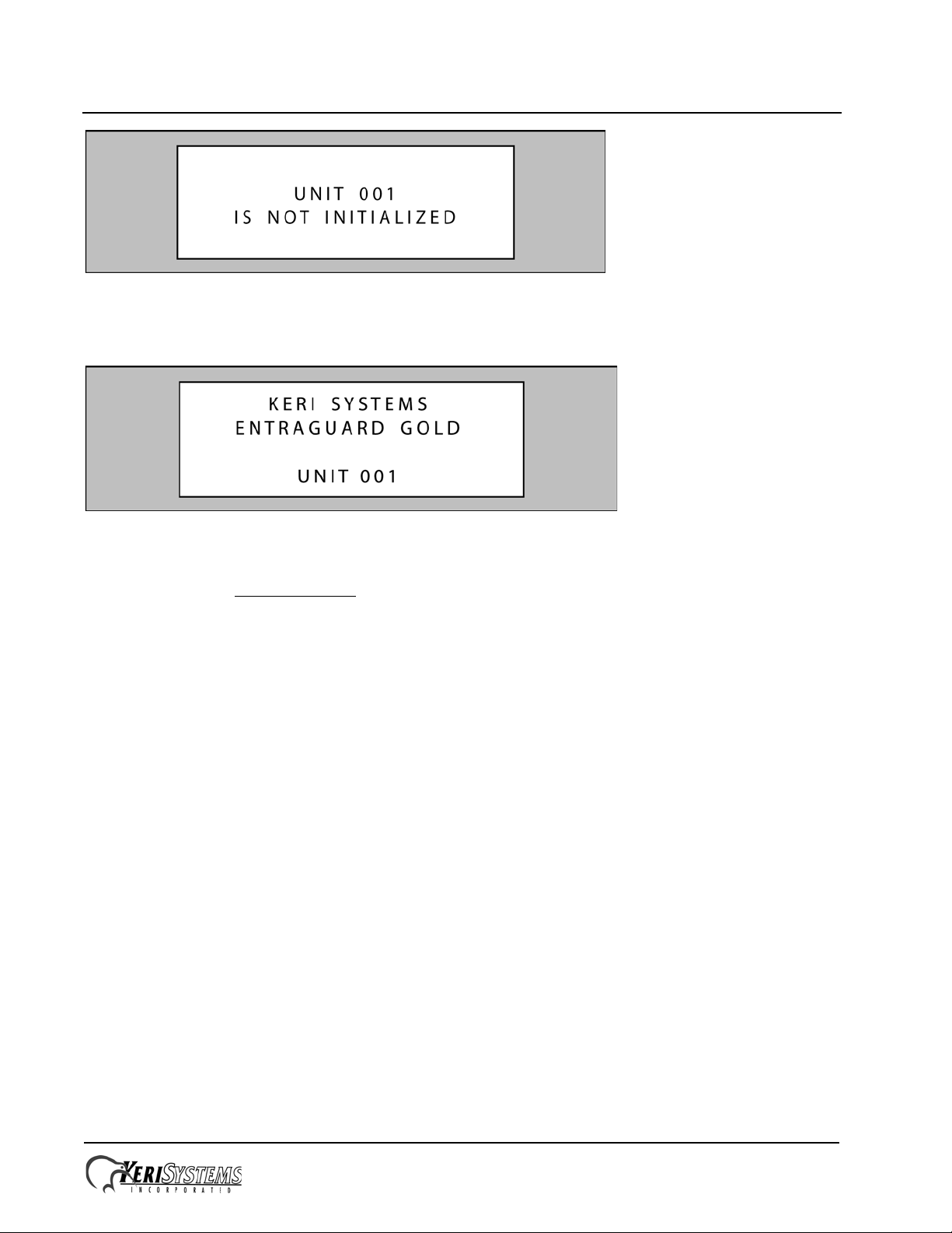
Once the memory has been cleared, the unit is ready to be configured. The LCD will display a warning that the unit has
not been initialized (see Figure 8 on page 10). This display will rotate with the EntraGuard Default display (see Figure
9 on page 10) until a Total Update from Doors has been performed on the unit. Once an update has been performed, only
the default will be displayed.
Page 9 of 12 P/N: 01535-001 Rev. A
Page 10
EntraGuard® Silver Walk-Up Package
Quick Start Guide
Figure 8: Not Initialized Unit Warning
NOTE: Any time the “Not Initialized Unit Warning” appears on the LCD display, the unit needs a Doors update.
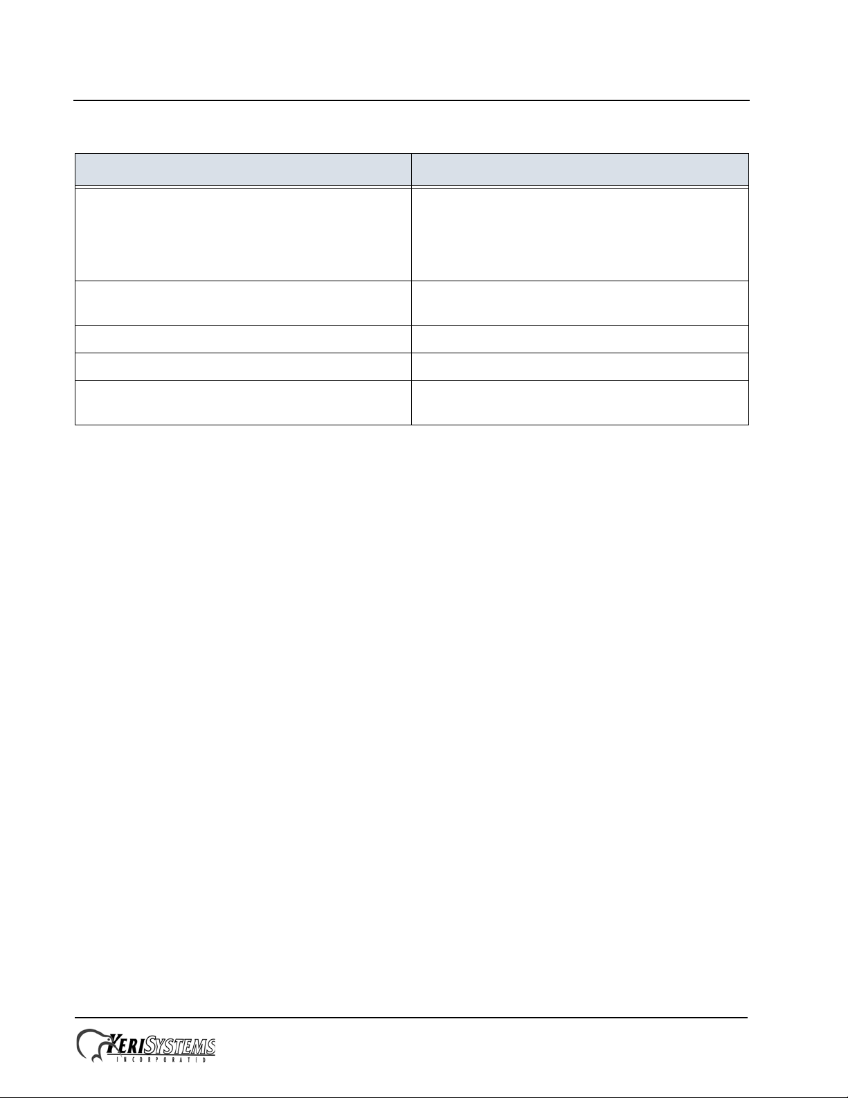
Figure 9: EntraGuard Silver Default LCD Display
NOTE: The default display will remain until a message banner has been created (for instructions on how to create a
message banner see the Doors Users Guide
the same, so this message will show the EntraGuard Gold banner in an Entraguard Silver unit.
- P/N 01914-100). Doors treats the Entraguard Gold and Entraguard Silver
7.1.1 The Master Controller
The Master Controller must be set to address 1 so that all slave controllers on the access control network can identify the
master controller. For the Master Controller to correctly identify all slave controllers on the network, one of two things
must be done.
1. The master controller must be the last unit on the network to be powered on. This ensures that when the Master
Controller begins polling the network to see what slave units are connected for system configuration, all slave units
are ready to communicate their unique addresses and their configuration information.
2. The Auto-Configuration routine within the Doo rs program must be run. This instructs the Master Controller to poll
all controllers on the network for addresses and configuration information.
If communication is being made using a direct serial connection to the PC, it is recommended that the PXL-500G-1 is the
Master Controller due to the 50-foot limitation of the RS-232 cable. The Master Controller must be assigned the address
of C001. Each additional unit (PXL/EntraGuard) must have a separate, uniqu e address.
If communication is being made via the use of the EntraGuard Silver’s internal modem, it is recommended that the
EntraGuard Silver is the Master Controller (with the assigned address of C001). In this situation the real-time event
monitoring feature in Doors cannot be used. An external modem may be used to connect to the PXL-500G-1 or the
EntraGuard Silver, however due to the 25-foot maximum cable distance, an EntraGuard is rarely used this way.
NOTE: An auto-configuration must be performed any time changes are made to the 485 network.
Page 10 of 12 P/N: 01535-001 Rev. A
Page 11

EntraGuard® Silver Walk-Up Package
Quick Start Guide
7.2 Clear the Controller’s RAM
When turning system power on for the first time, the controller’s memory needs to be cleared of any spurious information
that may be in the RAM. If you changed the controller address, the memory is automatically cleared. Howeve r, if you did
not change the address, you will need to clear the controller’s RAM separately. From the Reset Menu (see Figure 5 on
page 8), press 2 to Clear Memory. The Clear Memory screen will appear on the LCD (see Figure 10).
Figure 10: Clear Memory
From the Clear Memory Screen you may either:
1. Press 1 to clear the controller’s RAM. The LCD will change to show the memory is being cleared (see Figure 7 on
page 9). Once the controller’s RAM has been cleared, the unit is ready for use. The LCD will rotate between the
Initialization Warning and EntraGuard Default screens (see Figure 8 on page 10 and Figure 9 on page 10) until a
Total Update from Doors has been performed on the unit.
or
2. Press 2 to return to the Reset Menu without clearing the controller’s RAM.
NOTE: Clearing the system RAM completely erases all information within the EntraGuard Silver contr oller, except for the
controller address. If there is any information in system RAM from an access control installation and the system RAM is
cleared, the information in the controller is lost and cannot be recovered.
7.3 Diagnostics and Troubleshooting
For information regarding the diagnostics screens and troubleshooting the EntraGu a rd Silver Controller, see the
EntraGuard Troubleshooting and Diagnostics Guide
(P/N 01912-001).
Page 11 of 12 P/N: 01535-001 Rev. A
Page 12
EntraGuard® Silver Walk-Up Package
Quick Start Guide
8.0 Contact Keri Systems
Keri USA Keri UK, Ireland, Europe
2305 Bering Drive
San Jose, CA 95131
T elephone: (800) 260-5265
(408) 435-8400
Fax: (408) 577-1792 Fax:+ 44 (0) 1763 274 106
Web: www.kerisys.com Web:www.kerisystems.co.uk
E-mail: sales@kerisys.com
techsupport@kerisys.com
End of document.
Park Farm Industrial Estate
Telephone: + 44 (0) 1763 273 243
E-mail:sales@kerisystems.co.uk
tech-support@kerisystems.co.uk
Unit 17
Ermine Street
Buntingford
Herts SG9 9AZ UK
Page 12 of 12 P/N: 01535-001 Rev. A
 Loading...