

Page 1

EntraGuard Bronze
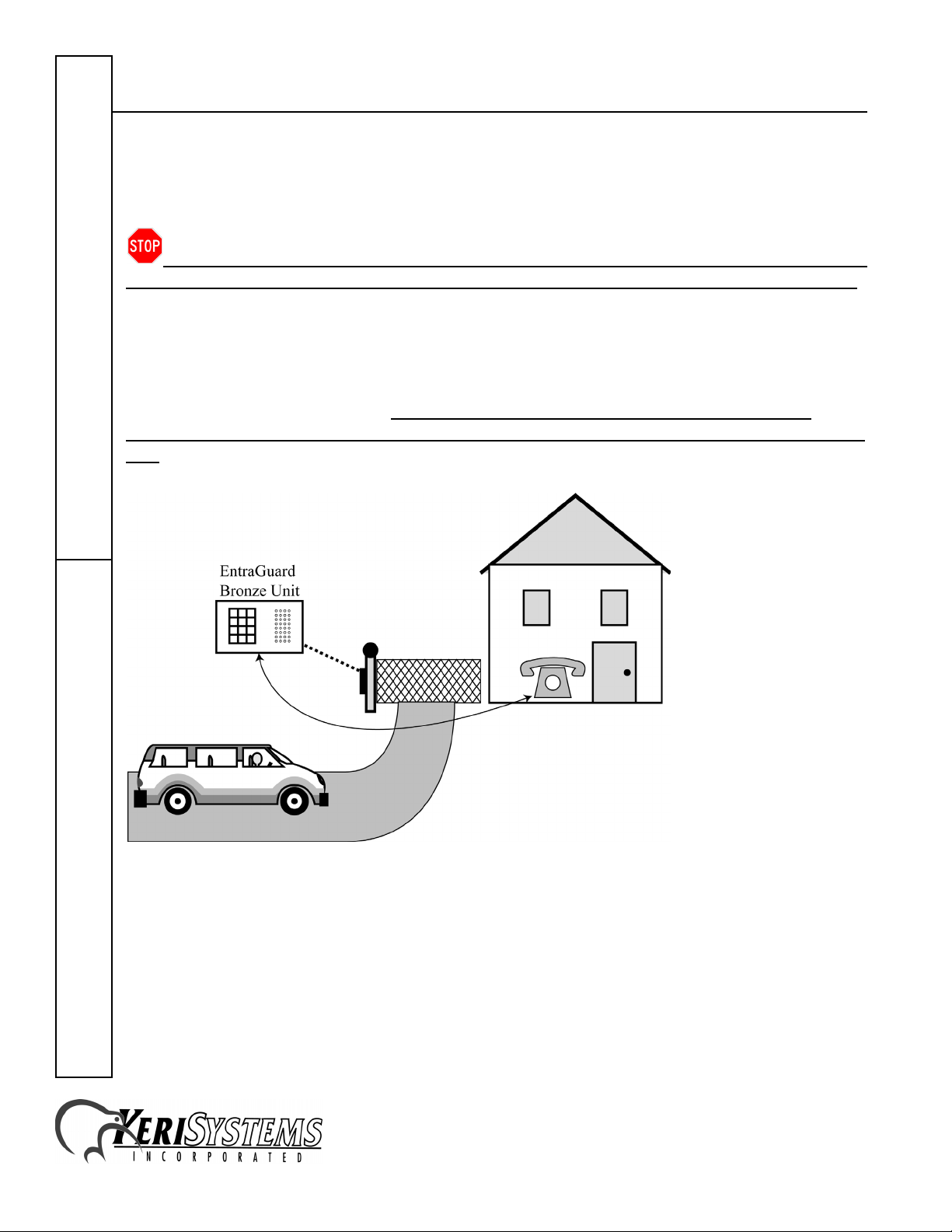
The EntraGuard Bronze is a residential telephone keypad entry system which allows a homeowner
to communicate directly with visitors and provide access by using any phone extension in the home.
Because the EntraGuard Bronze uses existing telephone lines, there is no need for added charges
which would be required by a dedicated phone line. The EntraGuard Bronze has the following
features.
• password protected entry for up to 50 users – pre-programmed with 4 Entry Codes, see the
EntraGuard Bronze Residence Guide (P/N 01911-003) for the codes
• an illuminated, waterproof keypad
• built-in microphone and speaker for hands-free communication
• Call Forwarding for instances when no one is home (forwarding to either another residential
telephone or a cellular telephone)
• Call Waiting to notify a visitor if the phone line is being used
• battery-backed memory
• two gate relays with individually programmable activation times
1.0 Specifications
• Size – 9.00 inches Wide x 6.25 inches High x 3.50 inches Deep
- 22.86 cm Wide x 15.9 cm High x 8.89 cm Deep
• Input Power – 24 VAC, .5amp, 20 VA plug-in transformer
• Relay Outputs (2) – SPDT, Contact Current: 1amp @ 24V
• Humidity – 0% to 95%
• FCC Registration – AL695Y-67614-07-E
Telephone EntryQuick Start Guide
2.0 Unit Installation
Before proceeding with the mounting and wiring of the EntraGuard Bronze system, verify your
mounting plans will meet all applicable Local, State, and Federal ADA mounting height and
accessibility building codes. Also verify you have a safe and secure path for routing all wiring.
2.1 Mounting Location
Locate the unit as near as possible to the controlled gate. Although the unit is resistant to
environmental factors, it should be protected from direct rain and snow.
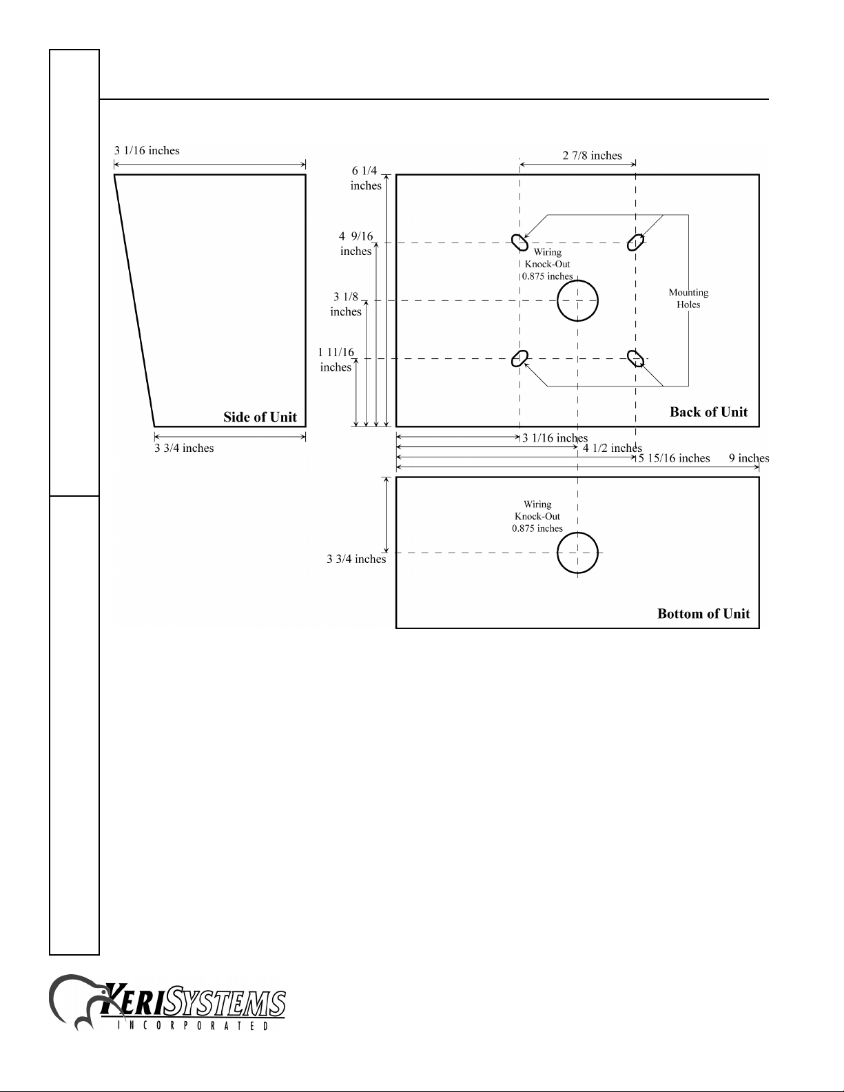
The unit has four mounting holes for pedestal mounting and two wiring knock-outs, one on the back
of the enclosure and one on the bottom (see Figure 1 on page 2). For wall mounting, choose a rigid
wall. For pedestal or fence mounting, provide enough bracing so the unit will not be subjected to
excessive shock or vibration when the gate is opened.
Due to the nature of this unit’s use, the unit may experience abuse and vandalism. Unit mounting
must be done in such a way as to minimize the effects of such treatment.
1530 Old Oakland Road, Suite 100 01911-001 Rev. J
San Jose, CA 95112 USA
(800) 260-5265 (408) 451-2520 FAX (408) 441-0309
Web: http://www.kerisys.com E-mail: sales@kerisys.com Page 1 of 32
Page 2
EntraGuard Bronze
Quick Start GuideTelephone Entry
Figure 1: EntraGuard Bronze Mounting Holes and Wiring Knock-Out
Typical mounting hardware is #10 x 1 1/2 inch wood screws into wall studs or 3/16 inch fasteners
into masonry. Provide additional framing or a backing plate when mounting the unit to paneled or
dry-walled areas. The more secure the unit location and mounting, the greater the level of on-going
unit integrity.
1530 Old Oakland Road, Suite 100 01911-001 Rev. J
San Jose, CA 95112 USA
(800) 260-5265 (408) 451-2520 FAX (408) 441-0309
Web: http://www.kerisys.com E-mail: sales@kerisys.com Page 2 of 32
Page 3
EntraGuard Bronze
2.2 System Wiring
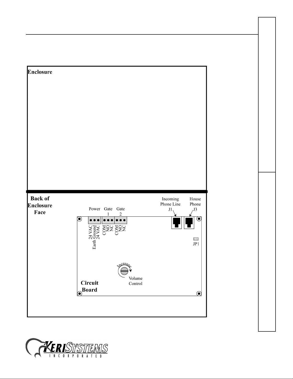
Refer to Figure 2 for wire connection locations for all instructions in Section 2.2.
Figure 2: Circuit Board Connections
Telephone EntryQuick Start Guide
1530 Old Oakland Road, Suite 100 01911-001 Rev. J
San Jose, CA 95112 USA
(800) 260-5265 (408) 451-2520 FAX (408) 441-0309
Web: http://www.kerisys.com E-mail: sales@kerisys.com Page 3 of 32
Page 4
EntraGuard Bronze
2.2.1 Earth Ground
For safety and for EMI noise reduction reasons, the EntraGuard Bronze’s enclosure must be earth
grounded. Using a ground wire, connect the unit’s enclosure to a known earth ground (such as a
ground rod or a conductive cold water pipe), observing all applicable codes.
2.2.2 Power
The EntraGuard Bronze uses a 20 VA plug-in transformer which must be plugged into an
unswitched (always ON), standard 120 VAC wall outlet. For best operating conditions:
• The outlet should be free from any other loads (preventing power fluctuations from affecting the
unit).
• Locate the outlet/transformer as close as possible to the unit.
• Ensure the transformer will not be accidentally unplugged from the outlet.
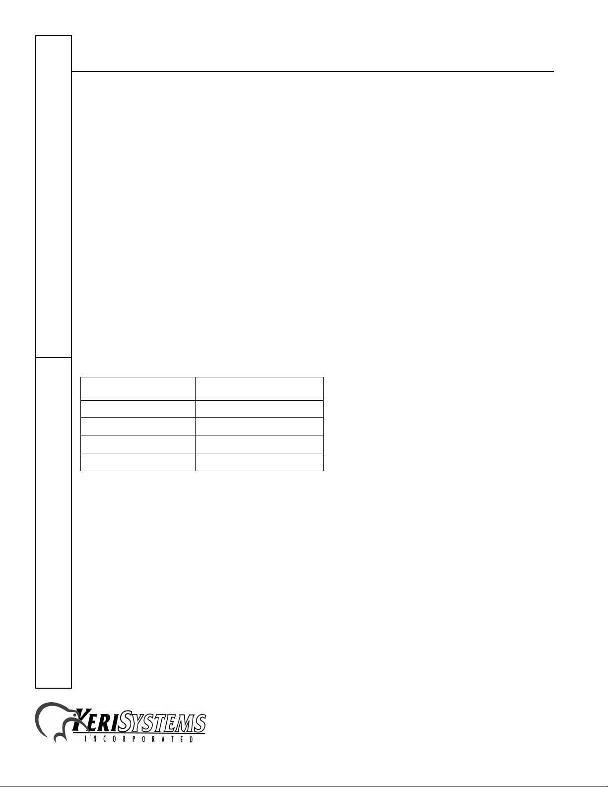
If the transformer cable length is not sufficient to reach from outlet to unit, additional cable can be
added. To ensure proper voltage and current at the unit, Table 1 lists the wire gauge to use based on
Quick Start GuideTelephone Entry
run distance.
Table 1: Recommended Wire Gauge per Run
Distance
Wire Length in Feet Minimum Wire Gauge
0 to 200 18
201 to 500 16
501 to 1000 14
1001 to 2000 12
1530 Old Oakland Road, Suite 100 01911-001 Rev. J
San Jose, CA 95112 USA
(800) 260-5265 (408) 451-2520 FAX (408) 441-0309
Web: http://www.kerisys.com E-mail: sales@kerisys.com Page 4 of 32
Page 5
EntraGuard Bronze
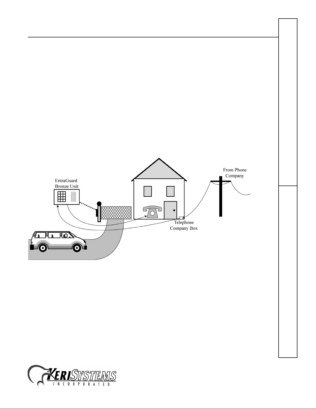
2.2.3 Phone Line
The EntraGuard Bronze does not require a separate control unit or second phone line. It is wired in
series with the incoming telephone service (Figure 3 on page 5). Using standard two-conductor
telephone cable and RJ-11 plugs, connect the incoming phone service to the J1-CO jack (Central
Office) on the EntraGuard Bronze PCB (see Figure 2 on page 3). Then connect the residential
phone system to the J3-Phone jack.
In applications where the residential phone system has multiple phone lines, only one incoming
telephone line can be designated as the telephone entry line, run through the EntraGuard Bronze
unit.
NOTE: Telephone wiring must be done to telephone industry standards to ensure the TIP and Ring
lines are correctly connected. If these lines are not correctly connected, the unit will not operate
properly.
Figure 3: In-Series Telephone Line Routing
1530 Old Oakland Road, Suite 100 01911-001 Rev. J
San Jose, CA 95112 USA
(800) 260-5265 (408) 451-2520 FAX (408) 441-0309
Web: http://www.kerisys.com E-mail: sales@kerisys.com Page 5 of 32
Telephone EntryQuick Start Guide
Page 6
EntraGuard Bronze
2.2.3.1 Intercom Jumper
The EntraGuard Bronze has a jumper that, when in place, turns the phone and Bronze connection
into an intercom without the need of an external phone line.
CAUTION: When the jumper is in place, the phone connected to the Bronze will not be able
to dial anything other than the Bronze unit. This also means that call forwarding will not work.
Make sure the phone line from the telephone is connected to the J3-Phone jack on the Bronze. Then,
to make the phone and EntraGuard Bronze act as an intercom without use of an external line, take
the jumper connector (provided in a separate plastic bag) and place it over the two pins of JP1 (see
Figure 2 on page 3). When the jumper is in place, the unit will act as a separate intercom with no
connection to external phone lines. Use this jumper with care. Even if an external line is
connected to the Bronze, the jumper in place will prevent the phone from dialing any outside
line.
Quick Start GuideTelephone Entry
Figure 4: Intercom Wiring
1530 Old Oakland Road, Suite 100 01911-001 Rev. J
San Jose, CA 95112 USA
(800) 260-5265 (408) 451-2520 FAX (408) 441-0309
Web: http://www.kerisys.com E-mail: sales@kerisys.com Page 6 of 32
Page 7
EntraGuard Bronze
2.2.4 Relays
There are two relays in the unit. Each relay can control a gate and each relay is activated by a
command from either the residence telephone or from the unit itself. Make the wiring connections
from the unit to your gate controller as are appropriate for the panel’s needs. Typically, a twoconductor, AWG 22 wire is sufficient, however a heavier gauge of wire may be required depending
upon the current demands of the gate controller panel and the wire run length. See Figure 2 on
page 3 for relay pinouts.
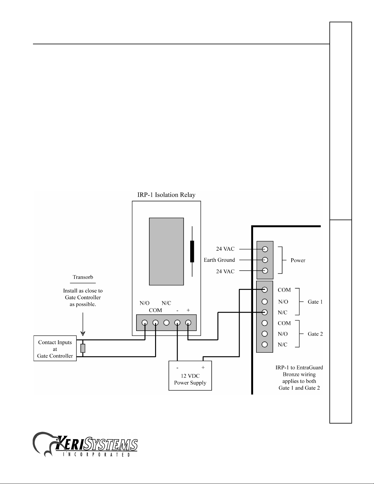
2.2.4.1 Isolation Relay for Transient Protection
Some gate controllers generate transients whenever the gate is opened (typically caused by the
starting of the gate motor when opening or closing the gate). These transients can be sent down the
relay lines to the EntraGuard Bronze unit, affecting unit operation. To guard against transients, a
Keri Systems IRP-1 can be installed on the relay line, isolating the unit from the gate controller. See
Figure 5 on page 7 for a wiring diagram.
Figure 5: IRP-1 Wiring Diagram
Telephone EntryQuick Start Guide
1530 Old Oakland Road, Suite 100 01911-001 Rev. J
San Jose, CA 95112 USA
(800) 260-5265 (408) 451-2520 FAX (408) 441-0309
Web: http://www.kerisys.com E-mail: sales@kerisys.com Page 7 of 32
Page 8
EntraGuard Bronze
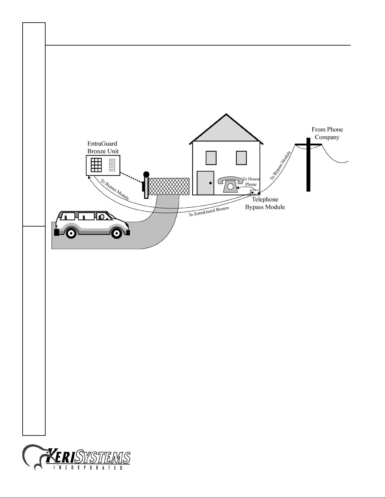
2.3 Telephone Bypass Module
The telephone bypass module may be installed so that in the event of a short in the EntraGuard
Bronze wiring, the EntraGuard Bronze unit may be bypassed, allowing the house phone to function
as normal. The Telephone Bypass Module (Keri Systems P/N 05608-001) must be purchased
separately from the EntraGuard Bronze.
Quick Start GuideTelephone Entry
Figure 6: Telephone Bypass Routing
1530 Old Oakland Road, Suite 100 01911-001 Rev. J
San Jose, CA 95112 USA
(800) 260-5265 (408) 451-2520 FAX (408) 441-0309
Web: http://www.kerisys.com E-mail: sales@kerisys.com Page 8 of 32
Page 9
EntraGuard Bronze
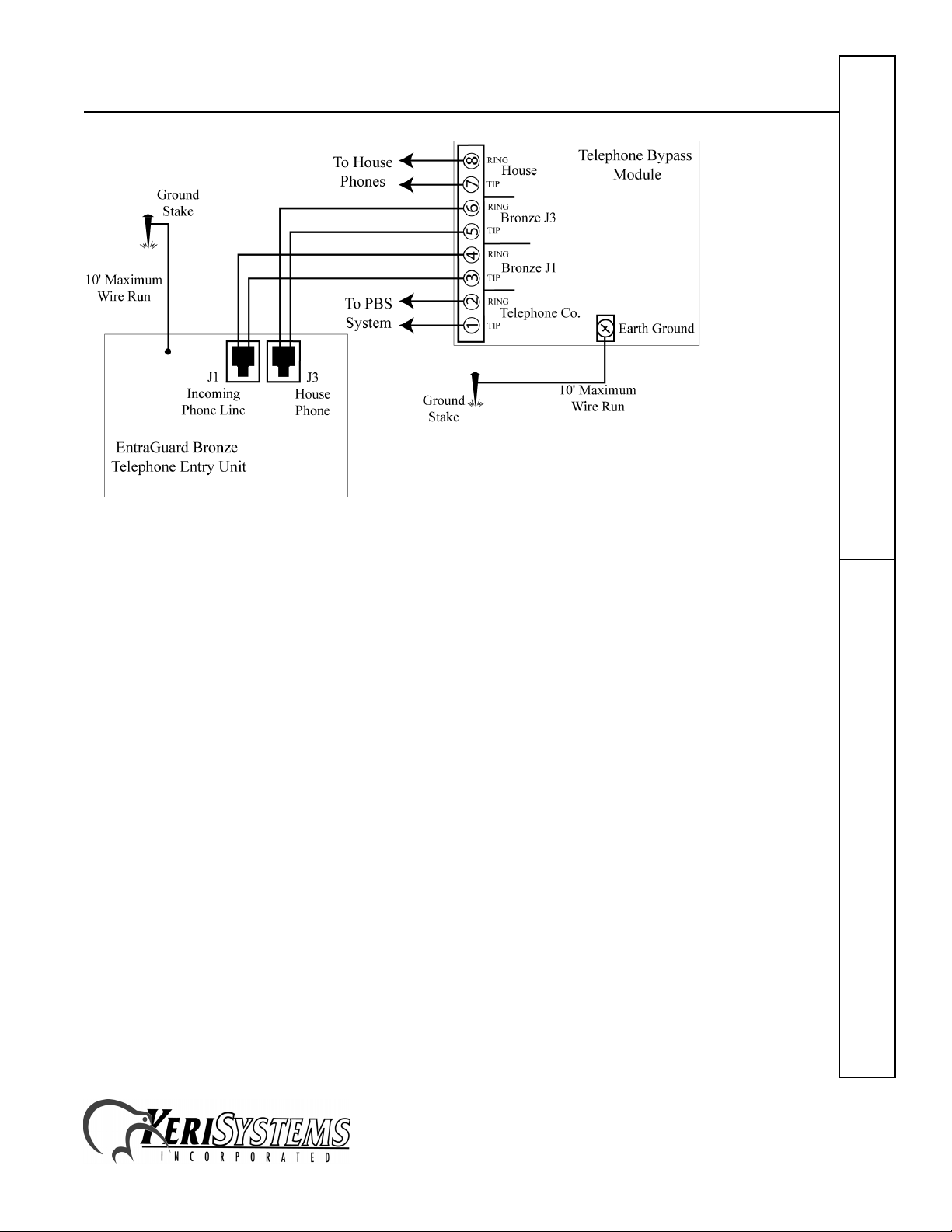
Figure 7: Bronze Telephone Bypass Module
1. Connect the bypass module’s EARTH GROUND terminal to a good earth ground.
2. Before connecting the incoming telephone line to the bypass module, check the polarity of the
wires with a DC voltmeter. Connect the negative wire (RING - usually green) to the bypass
module TELCO RING terminal. Connect the positive wire (TIP - usually red) to the bypass
module TELCO TIP terminal.
3. Connect the resident’s local telephone line RING (usually green) to the bypass module HOUSE
RING. Connect the local telephone line TIP (usually red) to the bypass module HOUSE TIP
terminal.
4. Connect the Bronze Incoming Phone Line RING (J1) to the bypass module RE-1 TELCO RING
terminal. Connect the Bronze Incoming Phone Line TIP (J1) to the bypass module RE-1
TELCO TIP terminal.
5. Connect the Bronze House Phone RING (J3) to the bypass module RE-1 HOUSE RING
terminal. Connect the Bronze House Phone TIP (J3) to the bypass module RE-1 HOUSE TIP
terminal.
2.4 Volume Control
The unit’s speaker volume can be adjusted via the Volume Control potentiometer on the circuit
board (Figure 2 on page 3). Rotate this potentiometer clockwise to increase volume.
NOTE: The microphone gain is pre-set and cannot be changed. This is done to minimize the chance
of feedback between microphone and speaker affecting system operation.
Telephone EntryQuick Start Guide
1530 Old Oakland Road, Suite 100 01911-001 Rev. J
San Jose, CA 95112 USA
(800) 260-5265 (408) 451-2520 FAX (408) 441-0309
Web: http://www.kerisys.com E-mail: sales@kerisys.com Page 9 of 32
Page 10
EntraGuard Bronze
3.0 Standard Operation
There are six standard operating modes used by the EntraGuard Bronze telephone entry system.
• Visitor Call – when an arriving visitor requests entry.
• Call Waiting – if you are already on the telephone when a visitor entry request is made.
• Call Forwarding – designating a telephone number to which an entry request is routed when you
know you will not be home.
• Remote Connection – allows you to connect to the EntraGuard Bronze unit from the residence
telephone and either program or remotely operate the unit.
• Gate Operation from the EntraGuard Bronze Unit – allows you to directly operate a gate from
the EntraGuard Bronze.
• Gate Operation from the Residence Telephone – allows you to directly operate a gate from the
residence telephone.
The enabling/disabling of operation modes and the setting of operating parameters is described in
Section 5.0 beginning on page 13.
Quick Start GuideTelephone Entry
3.1 Visitor Call
The Visitor Call command allows an arriving visitor to request entry by calling the residence
telephone through the EntraGuard Bronze unit.
1. An arriving visitor notifies the residence by pressing the “Call” key.
2. The residence telephone rings with the programmed ring pattern and number of rings.
3. When the residence telephone is answered, it connects to the EntraGuard Bronze unit and
conversation can begin.
4. The connection is automatically disconnected after a programmed amount of time (the default
time is 1 minute). The unit sounds a brief tone to warn both parties with a 3 second warning of
the impending disconnection.
5. The connection time can be extended on the residence telephone by pressing the key.
6. Communication can be terminated immediately and entry denied at any time by pressing the
key.
7. Communication can be terminated immediately and entry granted (by opening the gate) by
entering the desired gate activation code on the residence telephone keypad. When the code is
entered, communication with the unit is terminated and the desired gate relay is activated for the
programmed amount of time.
EXAMPLE: When connected, enter the following to open Gate 1 (assuming the activation code for
Gate 1 is “9”).
1530 Old Oakland Road, Suite 100 01911-001 Rev. J
San Jose, CA 95112 USA
(800) 260-5265 (408) 451-2520 FAX (408) 441-0309
Web: http://www.kerisys.com E-mail: sales@kerisys.com Page 10 of 32
Page 11

EntraGuard Bronze
3.2 Call Waiting
If a visitor attempts to notify the residence and the residence telephone is busy, the EntraGuard
Bronze generates a call waiting signal consisting of two, short, high-pitched beeps at three-second
intervals.
1. To put the original call on hold and respond to the EntraGuard Bronze unit, the residence
telephone user presses the key.
2. Once the connection to the EntraGuard Bronze is ended, the residence telephone automatically
reconnects to the call on hold.
3.3 Call Forwarding
If the Call Forwarding feature is enabled, the EntraGuard Bronze dials a programmed remote
telephone number instead of the residence telephone. If the remote number is busy, the EntraGuard
Bronze unit disconnects immediately.
3.4 Remote Connection
Remote Connection allows you to program the EntraGuard Bronze unit from the residence
telephone.
1. The residence telephone can connect to the EntraGuard Bronze at any time by pressing the
key three times with a brief delay between key presses.
2. Once connected, you must enter programming mode (see Section 5.1 on page 14) and then you
can begin programming the EntraGuard Bronze unit.
3.5 Gate Operation From The EntraGuard Bronze Unit
The Gate Operation from the EntraGuard Bronze Unit command allows you to immediately open a
gate from the Bronze unit.
• To open Gate 1 from the EntraGuard Bronze unit, press , press , and press the user’s
three-digit entry code.
• To open Gate 2 from the EntraGuard Bronze unit, press , press , and press the user’s
three-digit entry code.
• If a code entry mistake is made, the user can cancel the entry by pressing the key at any
time.
EXAMPLE: Enter the following to open Gate 1 from the EntraGuard Bronze unit with a user entry
code of “212.”
Telephone EntryQuick Start Guide
1530 Old Oakland Road, Suite 100 01911-001 Rev. J
San Jose, CA 95112 USA
(800) 260-5265 (408) 451-2520 FAX (408) 441-0309
Web: http://www.kerisys.com E-mail: sales@kerisys.com Page 11 of 32
Page 12

EntraGuard Bronze
3.6 Gate Operation From The Residence Telephone
Gate Operation from the Resident Telephone command allows you to immediately open a gate from
the residence telephone.
• To connect the residence telephone to the EntraGuard Bronze unit for gate operation, press
three times with a brief delay between key presses.
• To open Gate 1 from the EntraGuard Bronze unit, press , press , and press the user’s
three-digit entry code.
• To open Gate 2 from the EntraGuard Bronze unit, press , press , and press the user’s
three-digit entry code.
• If a code entry mistake is made, the user can cancel the entry by pressing the key at any
time.
EXAMPLE: Enter the following to open Gate 1 from the residence telephone with a user entry code
Quick Start GuideTelephone Entry
of “212.”
4.0 Resetting the EntraGuard Bronze’s Microprocessor
The EntraGuard Bronze comes with basic features pre-programmed. To reset the microprocessor
(and clear all pre-programming), perform the following steps.
1. Turn unit power OFF.
2. Press and hold the and keys.
3. Turn unit power ON.
4. Release the and keys.
The unit is now reset.
NOTE: Performing a reset completely erases ALL pre-programming and restores the EntraGuard
Bronze to the factory defaults.
1530 Old Oakland Road, Suite 100 01911-001 Rev. J
San Jose, CA 95112 USA
(800) 260-5265 (408) 451-2520 FAX (408) 441-0309
Web: http://www.kerisys.com E-mail: sales@kerisys.com Page 12 of 32
Page 13

EntraGuard Bronze
5.0 Programming
All operating parameters are programmable from either the EntraGuard Bronze’s front panel
keypad or from any telephone in the residence connected to the same phone line as the EntraGuard
Bronze unit. There are 19 commands available.
• Add Entry Code – allows a user to activate a gate relay from the EntraGuard Bronze unit
• Delete Entry Code – deletes a users entry code
• Delete All Entry Codes – delete all user entry code
• Reset System – resets all programmable values to factory default settings
• Set Programming Mode Code – sets the entry code used to enter program parameters
• Set Ring Mode – sets the ring pattern used when a visitor requests entry
• Set Maximum Rings – sets the maximum number of rings used when a visitor requests entry
• Set Gate 1 Relay Access Code – allows a user to activate the gate 1 relay from the residence
telephone
• Set Gate 1 Relay Timeout – sets the amount of time the gate 1 relay is activated
• Set Gate 2 Relay Access Code – allows a user to activate the gate 2 relay from the residence
telephone
• Set Gate 2 Relay Timeout – sets the amount of time the gate 2 relay is activated
• Set Call Forwarding Telephone Number – sets an alternate telephone number to which entrance
request calls can be forwarded
• Enable Call Forwarding – enables the call forwarding feature
• Disable Call Forwarding – disables the call forwarding feature
• Set Maximum Connection Time – sets the maximum amount of time the telephone line is active
when a visitor requests entry
• Hold Open Gate 1 – immediately holds open the gate 1 relay open for a finite period of time
• Close Gate 1 – immediately closes the gate 1 relay
• Hold Open Gate 2 – immediately holds open the gate 2 relay open for a finite period of time
• Close Gate 2 – immediately closes the gate 2 relay
Telephone EntryQuick Start Guide
When entering programming commands, the unit responds to correct entries with a short, highpitched tone to indicate the command was accepted. The unit responds to incorrect/invalid entries
with a short, high-pitched tone followed by a low-pitched tone to indicate the command was
rejected.
1530 Old Oakland Road, Suite 100 01911-001 Rev. J
San Jose, CA 95112 USA
(800) 260-5265 (408) 451-2520 FAX (408) 441-0309
Web: http://www.kerisys.com E-mail: sales@kerisys.com Page 13 of 32
Page 14

EntraGuard Bronze
5.1 Entering Programming Mode
The EntraGuard Bronze unit must be in programming mode to set any of the unit’s operating
parameters. The EntraGuard Bronze unit is pre-programmed with a Programming Code, see the
EntraGuard Bronze Residence Guide (P/N 01911-003) for the code. The factory default is
“999999.”
5.1.1 Entering Programming Mode from the Bronze Unit
1. Press the key three times.
2. Enter the six-digit pre-programmed code.
3. The unit emits a short high-pitched tone to indicate the code was accepted. For security reasons,
the unit does not emit any sounds to indicate if an incorrect code has been entered.
Quick Start GuideTelephone Entry
EXAMPLE: Enter the following to enter a Programming Code of “135246.”
5.1.2 Entering Programming Mode from the Residence Telephone
1. Press the key three times.
2. Enter the six-digit pre-programmed code.
3. The unit emits a short high-pitched tone to indicate the code was accepted. For security reasons,
the unit does not emit any sounds to indicate if an incorrect code has been entered.
EXAMPLE: Enter the following to enter a Programming Code of “135246.”
5.2 Exiting Programming Mode
When programming from the EntraGuard Bronze unit, the unit exits programming mode after 1
minute of keypad inactivity. To exit programming mode immediately after entering a programming
command, press .
To exit programming mode when using the residence telephone, press or simply hang up.
1530 Old Oakland Road, Suite 100 01911-001 Rev. J
San Jose, CA 95112 USA
(800) 260-5265 (408) 451-2520 FAX (408) 441-0309
Web: http://www.kerisys.com E-mail: sales@kerisys.com Page 14 of 32
Page 15

EntraGuard Bronze
5.3 Program Commands
Once in programming mode, you can change any of the EntraGuard Bronze’s programmable
commands. The general process for changing an existing command value is as follows:
1. Enter the two-digit programming command code for the command you wish to change.
2. If applicable, enter the new value (some commands simply enable or disable a feature and do
not have an associated value).
- If an entry error has been made, press and start again from Step 1.
3. Press to lock in the change.
- If the entry is valid, the unit emits a short, high-pitched tone to indicate the change has been
accepted.
- If the entry is invalid, the unit emits a short, high-pitched tone followed by a low-pitched
tone to indicate the change has been rejected.
4. Return to Step 1 to enter another program command change, or to exit programming mode,
either press or hang up (if using the residence telephone).
Programming examples are provided with each of the commands described below.
5.3.1 Add Entry Code
An Entry Code is a three-digit number entered at the EntraGuard Bronze unit which allows the user
to activate a gate relay (see “Gate Operation From The EntraGuard Bronze Unit” on page 11). You
can have up to 50 entry codes. The EntraGuard Bronze comes with four pre-programmed Entry
Codes, see the EntraGuard Bronze Residence Guide (P/N 01911-003). The factory default is “123.”
Perform the following to add an entry code.
1. Press .
2. Enter the desired three-digit entry code – .
3. Press to lock in the new entry code. The unit emits a short, high-pitched tone to indicate the
new entry code has been accepted. The unit emits a short, high-pitched tone followed by a lowpitched tone if the entry code has been rejected.
EXAMPLE: Enter the following to set an Entry Code of “159.”
Telephone EntryQuick Start Guide
4. You can now enter another program command or press to exit programming mode.
1530 Old Oakland Road, Suite 100 01911-001 Rev. J
San Jose, CA 95112 USA
(800) 260-5265 (408) 451-2520 FAX (408) 441-0309
Web: http://www.kerisys.com E-mail: sales@kerisys.com Page 15 of 32
Page 16

EntraGuard Bronze
5.3.2 Delete Entry Code
Entry codes can be deleted as required to prevent gate activation by that entry code. Perform the
following to delete an entry code.
1. Press .
2. Enter the desired three-digit entry code to delete – .
3. Press to delete the entry code. The unit emits a short, high-pitched tone to indicate the
deletion has been accepted. The unit emits a short, high-pitched tone followed by a low-pitched
tone if the deletion has been rejected.
EXAMPLE: Enter the following to Delete an Entry Code of “159.”
Quick Start GuideTelephone Entry
4. You can now enter another program command or press to exit programming mode.
5.3.3 Delete All Entry Codes
ALL entry codes can be deleted by this one command. Perform the following to delete all entry
codes and no longer allow gate activation by any entry code.
1. Press .
2. Press to delete all entry codes. The unit emits a short, high-pitched tone to indicate the
deletions have been accepted.
EXAMPLE: Enter the following to Delete All Entry Codes.
3. You can now enter another program command or press to exit programming mode.
1530 Old Oakland Road, Suite 100 01911-001 Rev. J
San Jose, CA 95112 USA
(800) 260-5265 (408) 451-2520 FAX (408) 441-0309
Web: http://www.kerisys.com E-mail: sales@kerisys.com Page 16 of 32
Page 17

EntraGuard Bronze
5.3.4 Reset System
Resetting the System returns all programmable values to their factory default settings. Perform the
following to reset the EntraGuard Bronze system.
1. Press .
2. Press to reset the system. The unit emits a short, high-pitched tone to indicate the reset has
been accepted.
EXAMPLE: Enter the following to Reset the System.
3. You can now enter another program command or press to exit programming mode.
5.3.5 Set Programming Mode Entry Code
To increase system security, you have the option to change the code number required to enter
programming mode. The EntraGuard Bronze unit has been pre-programmed with a unique
Programming Code, see the EntraGuard Bronze Residence Guide (P/N 01911-003) for this code.
NOTE: To ensure the security of your EntraGuard Bronze system, Keri Systems strongly
recommends that you perform this command if your Programming Code has been discovered by
anyone who should not know it.
This code number must be six-digits long. For security reasons, certain consecutive strings of
numbers are not accepted; for example, “123456” is not accepted. Perform the following to set the
programming mode entry code.
1. Press .
2. Enter the desired six-digit programming mode entry code – .
3. Press to lock in the new programming mode entry code. The unit emits a short, highpitched tone to indicate the new code has been accepted. The unit emits a short, high-pitched
tone followed by a low-pitched tone if the programming mode entry code has been rejected.
EXAMPLE: Enter the following to set a Programming Mode Entry Code of “135246.”
4. You can now enter another program command or press to exit programming mode.
Telephone EntryQuick Start Guide
1530 Old Oakland Road, Suite 100 01911-001 Rev. J
San Jose, CA 95112 USA
(800) 260-5265 (408) 451-2520 FAX (408) 441-0309
Web: http://www.kerisys.com E-mail: sales@kerisys.com Page 17 of 32
Page 18

EntraGuard Bronze
5.3.6 Set Ring Mode
The Ring Mode allows you to set the type of ring generated when the EntraGuard Bronze unit calls
the residence telephone. Two ring modes are available.
• Type 1 – three short rings followed by a long pause (the default setting)
• Type 2 – two medium rings followed by a long pause
Perform the following to set the ring mode.
1. Press .
2. Enter the desired ring type – .
3. Press to lock in the new ring type. The unit emits a short, high-pitched tone to indicate the
new ring type has been accepted. The unit emits a short, high-pitched tone followed by a low-
Quick Start GuideTelephone Entry
pitched tone if the ring type has been rejected.
EXAMPLE: Enter the following to set Ring Type “1.”
4. You can now enter another program command or press to exit programming mode.
5.3.7 Set Maximum Rings
The Maximum Rings allows you to set the maximum number of rings the EntraGuard Bronze
makes when the unit calls the residence telephone. The pre-programmed value has been set at “2”
rings. The factory default value is “6” rings; the maximum value is “19” rings. Entering “0” sets the
unit to ring until it is answered or the key is pressed on the Bronze unit (no maximum ring
value). Perform the following to set the maximum number of rings.
1. Press .
2. Enter the desired number of rings – .
3. Press to lock in the maximum number of rings. The unit emits a short, high-pitched tone to
indicate the maximum number of rings has been accepted. The unit emits a short, high-pitched
tone followed by a low-pitched tone if the number of rings has been rejected.
1530 Old Oakland Road, Suite 100 01911-001 Rev. J
San Jose, CA 95112 USA
(800) 260-5265 (408) 451-2520 FAX (408) 441-0309
Web: http://www.kerisys.com E-mail: sales@kerisys.com Page 18 of 32
Page 19

EntraGuard Bronze
EXAMPLE: Enter the following to set the maximum number of rings to “10.”
4. You can now enter another program command or press to exit programming mode.
5.3.8 Set Gate 1 Relay Access Code
The Gate 1 Relay Access Code is a single-digit number that, when entered at the residence
telephone, activates gate relay 1 allowing access. Perform the following to set the gate 1 relay
access code.
1. Press .
2. Enter the desired relay 1 activation code – (default code is “9”).
3. Press to lock in the new gate 1 relay access code. The unit emits a short, high-pitched tone
to indicate the gate 1 relay access code has been accepted. The unit emits a short, high-pitched
tone followed by a low-pitched tone if the gate 1 relay access code has been rejected.
EXAMPLE: Enter the following to set a Relay 1 Activation Code of “5.”
4. You can now enter another program command or press to exit programming mode.
5.3.9 Set Gate 1 Relay Timeout
The Gate 1 Relay Timeout sets the time, in seconds, that the gate 1 relay is activated. The timeout
value range is from 1 to 65 seconds; if you enter 0, the relay will never open. Perform the following
to set the gate 1 relay timeout value.
1. Press .
2. Enter the desired gate 1 relay timeout value – (default value is 5 seconds). If the
entered timeout value is out of range an error tone sounds and the input is ignored.
3. Press to lock in the new gate 1 relay timeout value. The unit emits a short, high-pitched
tone to indicate the gate 1 relay timeout value has been accepted. The unit emits a short, highpitched tone followed by a low-pitched tone if the gate 1 relay timeout value has been rejected.
Telephone EntryQuick Start Guide
1530 Old Oakland Road, Suite 100 01911-001 Rev. J
San Jose, CA 95112 USA
(800) 260-5265 (408) 451-2520 FAX (408) 441-0309
Web: http://www.kerisys.com E-mail: sales@kerisys.com Page 19 of 32
Page 20

EntraGuard Bronze
EXAMPLE: Enter the following to set a Gate 1 Relay Timeout value of “30” seconds.
4. You can now enter another program command or press to exit programming mode.
5.3.10 Set Gate 2 Relay Access Code
The Gate 2 Relay Access Code is a single-digit number that, when entered at the residence
telephone, activates gate relay 2 allowing access. Perform the following to set the gate 2 relay
access code.
1. Press .
2. Enter the desired relay 2 activation code – (default code is “2”).
Quick Start GuideTelephone Entry
3. Press to lock in the new relay 2 activation code. The unit emits a short, high-pitched tone to
indicate the relay 2 activation code has been accepted. The unit emits a short, high-pitched tone
followed by a low-pitched tone if the relay 2 activation code has been rejected.
EXAMPLE: Enter the following to set a Relay 2 Activation Code of “6.”
4. You can now enter another program command or press to exit programming mode.
5.3.11 Set Gate 2 Relay Timeout
The Gate 2 Relay Timeout sets the time, in seconds, that the gate 2 relay is activated. The timeout
value range is from 1 to 65 seconds; if you enter 0, the relay will never open. Perform the following
to set the gate 2 relay timeout value.
1. Press .
2. Enter the desired gate 2 relay timeout value – (default value is 5 seconds). If the
entered timeout value is out of range an error tone sounds and the input is ignored.
3. Press to lock in the new gate 2 relay timeout value. The unit emits a short, high-pitched
tone to indicate the gate 2 relay timeout value has been accepted. The unit emits a short, highpitched tone followed by a low-pitched tone if the gate 2 relay timeout value has been rejected.
1530 Old Oakland Road, Suite 100 01911-001 Rev. J
San Jose, CA 95112 USA
(800) 260-5265 (408) 451-2520 FAX (408) 441-0309
Web: http://www.kerisys.com E-mail: sales@kerisys.com Page 20 of 32
Page 21

EntraGuard Bronze
EXAMPLE: Enter the following to set a Gate 2 Relay Timeout value of “45” seconds.
4. You can now enter another program command or press to exit programming mode.
5.3.12 Set Call Forwarding Phone Number
The Call Forwarding Phone Number allows you to enter the telephone number to be dialed by the
EntraGuard Bronze unit when you enable call forwarding. This telephone number can be up to 20
digits long. Typically this command is used when you will not be in the residence, but you still need
to be able to grant access to a visitor. When this feature is activated (see “Enable Call Forwarding”)
and a visitor requests entry, the EntraGuard Bronze will dial the call forwarding telephone number
instead of the residence telephone number. Perform the following to set the call forwarding
telephone number.
1. Press .
2. Enter the desired call forwarding telephone number – .
3. Press to lock in the call forwarding telephone number. The unit emits a short, high-pitched
tone to indicate the call forwarding telephone number has been accepted. The unit emits a short,
high-pitched tone followed by a low-pitched tone if the call forwarding telephone number has
been rejected.
EXAMPLE: Enter the following to set a call forwarding telephone number of “555 1212.”
4. You can now enter another program command or press to exit programming mode.
Telephone EntryQuick Start Guide
1530 Old Oakland Road, Suite 100 01911-001 Rev. J
San Jose, CA 95112 USA
(800) 260-5265 (408) 451-2520 FAX (408) 441-0309
Web: http://www.kerisys.com E-mail: sales@kerisys.com Page 21 of 32
Page 22

EntraGuard Bronze
5.3.13 Enable Call Forwarding
The Enable Call Forwarding command allows you to enable the EntraGuard Bronze unit to perform
call forwarding. A call forwarding telephone number must have already been programmed into the
EntraGuard Bronze unit (see “Set Call Forwarding Phone Number”). Typically this command is
used when you will not be in the residence, but you still need to be able to grant access to a visitor.
When this feature is activated and a visitor requests entry, the EntraGuard Bronze will dial the call
forwarding telephone number instead of the residence telephone number. Perform the following to
enable call forwarding.
1. Press . If a call forwarding telephone number has not already been entered an error
tone sounds and the input is ignored.
2. Press to enable call forwarding. The unit emits a short, high-pitched tone followed by a
low-pitched tone to indicate call forwarding has been enabled.
Quick Start GuideTelephone Entry
EXAMPLE: Enter the following to Enable Call Forwarding.
3. You can now enter another program command or press to exit programming mode.
5.3.14 Disable Call Forwarding
The Disable Call Forwarding command allows you to disable the EntraGuard Bronze unit to
perform call forwarding. Perform the following to disable call forwarding.
1. Press . If a call forwarding telephone number has not already been entered an error
tone sounds and the input is ignored.
2. Press to disable call forwarding. The unit emits a short, high-pitched tone followed by a
low-pitched tone to indicate the call forwarding has been disabled.
EXAMPLE: Enter the following to Disable Call Forwarding.
3. You can now enter another program command or press to exit programming mode.
1530 Old Oakland Road, Suite 100 01911-001 Rev. J
San Jose, CA 95112 USA
(800) 260-5265 (408) 451-2520 FAX (408) 441-0309
Web: http://www.kerisys.com E-mail: sales@kerisys.com Page 22 of 32
Page 23

EntraGuard Bronze
5.3.15 Set Maximum Connection Time
The Set Maximum Connection Time command allows you to set the maximum amount of time the
connection between the EntraGuard Bronze unit and the residence telephone remains active. Once
this time has passed, the Bronze unit releases the phone line providing the normal dial tone. The
factory default value is 60 seconds; the maximum value is 65 seconds. Entering a value of 0 sets the
unit to not allow a connection. Perform the following to set the maximum connection time.
1. Press .
2. Enter the desired maximum connection time value – (default is 60 seconds).
3. Press to lock in the new maximum connection time. The unit emits a short, high-pitched
tone to indicate the new maximum connection time has been accepted. The unit emits a short,
high-pitched tone followed by a low-pitched tone if the maximum connection time has been
rejected.
EXAMPLE: Enter the following to set the maximum connection time to “45” seconds.
4. You can now enter another program command or press to exit programming mode.
5.3.16 Hold-Open Gate 1
The Hold-Open Gate 1 command allows you to immediately activate the gate 1 relay for the
specified period of time. The time range is from 1 to 99998 minutes (approximately 69.5 days). If
no value is entered, gate 1 remains open until a Close Gate 1 command is issued (see “Close Gate
1” on page 24). Once the command is issued, the gate is opened immediately.
Perform the following to hold gate 1 open for a finite period of time.
1. Press .
2. Enter the desired gate 1 hold-open value – .
3. Press to lock in the gate 1 hold-open value. The unit emits a short, high-pitched tone to
indicate the gate 1 hold-open value has been accepted. The unit emits a short, high-pitched tone
followed by a low-pitched tone if the gate 1 hold-open time has been rejected.
Telephone EntryQuick Start Guide
1530 Old Oakland Road, Suite 100 01911-001 Rev. J
San Jose, CA 95112 USA
(800) 260-5265 (408) 451-2520 FAX (408) 441-0309
Web: http://www.kerisys.com E-mail: sales@kerisys.com Page 23 of 32
Page 24

EntraGuard Bronze
EXAMPLE: Enter the following to hold gate 1 open for “15” minutes.
4. You can now enter another program command or press to exit programming mode.
Perform the following to hold gate 1 open indefinitely.
1. Press .
2. Press to hold-open gate 1 indefinitely. The unit emits a short, high-pitched tone followed
by a low-pitched tone to indicate the gate 1 hold-open command has been accepted. The unit
emits a short, high-pitched tone followed by a low-pitched tone if the gate 1 hold-open time has
been rejected.
Quick Start GuideTelephone Entry
EXAMPLE: Enter the following to hold gate 1 open indefinitely.
3. You can now enter another program command or press to exit programming mode.
5.3.17 Close Gate 1
The Close Gate 1 command is used to immediately close a gate. Typically this command is used to
close a gate that has been held-open indefinitely, or to close a gate before its programmed hold-open
time expires. Perform the following to close gate 1 immediately.
1. Press .
2. Press to close gate 1 immediately. The unit emits a short, high-pitched tone followed by a
low-pitched tone to indicate the close gate 1 command has been accepted. The unit emits a
short, high-pitched tone followed by a low-pitched tone if the gate 1 hold-open time has been
rejected.
EXAMPLE: Enter the following to close gate 1 immediately.
3. You can now enter another program command or press to exit programming mode.
1530 Old Oakland Road, Suite 100 01911-001 Rev. J
San Jose, CA 95112 USA
(800) 260-5265 (408) 451-2520 FAX (408) 441-0309
Web: http://www.kerisys.com E-mail: sales@kerisys.com Page 24 of 32
Page 25

EntraGuard Bronze
5.3.18 Hold-Open Gate 2
The Hold-Open Gate 2 command allows you to immediately activate the gate 2 relay for the
specified period of time. The time range is from 1 to 99998 minutes (approximately 69.5 days). If
no value is entered, Gate 2 remains open until a Close Gate 2 command is issued (see “Close Gate
2” on page 26). Once the command is issued, the gate is opened immediately.
Perform the following to hold gate 2 open for a finite period of time.
1. Press .
2. Enter the desired gate 2 hold-open value – .
3. Press to lock in the gate 2 hold-open value. The unit emits a short, high-pitched tone to
indicate the gate 2 hold-open value has been accepted. The unit emits a short, high-pitched tone
followed by a low-pitched tone if the gate 2 hold-open time has been rejected.
EXAMPLE: Enter the following to hold gate 2 open for “5” minutes.
4. You can now enter another program command or press to exit programming mode.
Perform the following to hold gate 2 open indefinitely.
1. Press .
2. Press to hold-open gate 2 indefinitely. The unit emits a short, high-pitched tone to indicate
the gate 2 hold-open command has been accepted. The unit emits a short, high-pitched tone
followed by a low-pitched tone if the gate 2 hold-open time has been rejected.
EXAMPLE: Enter the following to hold gate 2 open indefinitely.
3. You can now enter another program command or press to exit programming mode.
Telephone EntryQuick Start Guide
1530 Old Oakland Road, Suite 100 01911-001 Rev. J
San Jose, CA 95112 USA
(800) 260-5265 (408) 451-2520 FAX (408) 441-0309
Web: http://www.kerisys.com E-mail: sales@kerisys.com Page 25 of 32
Page 26

EntraGuard Bronze
5.3.19 Close Gate 2
The Close Gate 2 command is used to immediately close a gate. Typically this command is used to
close a gate that has been held-open indefinitely, or to close a gate before its programmed hold-open
time expires. Perform the following to close gate 2 immediately.
1. Press .
2. Press to close gate 2 immediately. The unit emits a short, high-pitched tone to indicate the
close gate 2 command has been accepted. The unit emits a short, high-pitched tone followed by
a low-pitched tone if the gate 2 hold-open time has been rejected.
EXAMPLE: Enter the following to close gate 2 immediately.
Quick Start GuideTelephone Entry
3. You can now enter another program command or press to exit programming mode.
1530 Old Oakland Road, Suite 100 01911-001 Rev. J
San Jose, CA 95112 USA
(800) 260-5265 (408) 451-2520 FAX (408) 441-0309
Web: http://www.kerisys.com E-mail: sales@kerisys.com Page 26 of 32
Page 27

EntraGuard Bronze
6.0 Table of Basic Operation Commands
Operation Instructions
Visitor Call
• Visitor notifies residence by pressing key.
• Resident answers telephone.
• Resident disconnects immediately by pressing key.
• Resident allows gate entry by pressing – where “x” is
the gate access code.
Call Waiting
• Visitor notifies residence by pressing key.
• Resident hears the call waiting signal of two, short, highpitched beeps at three-second intervals.
Gate Operation from the
EntraGuard Bronze Unit
Gate Operation from the
Residence Telephone
• Resident presses to place original call on hold.
• When visitor call is ended, the original call is restored.
• Press (the gate entry code) to open
gate 1.
• Press (the gate entry code) to open
gate 2.
• Press .
• Press (the gate entry code) to open
gate 1.
• Press (the gate entry code) to open
gate 2.
Telephone EntryQuick Start Guide
1530 Old Oakland Road, Suite 100 01911-001 Rev. J
San Jose, CA 95112 USA
(800) 260-5265 (408) 451-2520 FAX (408) 441-0309
Web: http://www.kerisys.com E-mail: sales@kerisys.com Page 27 of 32
Page 28

EntraGuard Bronze
7.0 Table of Programming Commands
Programming commands can be performed at the EntraGuard Bronze unit or the residence
telephone.
Programming Command Instructions
Enter Programming Mode
• Press .
From the Bronze Unit
• Press – the six-digit
programming code.
• The unit emits a short high-pitched tone to indicate the unit is
in programming mode. If no sound is emitted an invalid
programming code has been entered.
Enter Programming Mode
Quick Start GuideTelephone Entry
• Press .
From the Residence
Telephone
• Press – the six-digit
programming code.
• The unit emits a short high-pitched tone to indicate the unit is
in programming mode. If no sound is emitted an invalid
programming code has been entered.
All subsequent commands assume the EntraGuard Bronze unit is in Programming Mode.
Add an Entry Code
• Press .
Default = 123
• Press – the desired entry code.
• Press . The unit emits a short high-pitched tone to indicate
the code has been accepted. A high-low tone is emitted if an
invalid programming code has been entered.
Delete an Entry Code
• Press .
• Press – the entry code to be deleted.
• Press . The unit emits a short high-pitched tone to indicate
the code has been deleted. A high-low tone is emitted if an
invalid entry code has been entered.
1530 Old Oakland Road, Suite 100 01911-001 Rev. J
San Jose, CA 95112 USA
(800) 260-5265 (408) 451-2520 FAX (408) 441-0309
Web: http://www.kerisys.com E-mail: sales@kerisys.com Page 28 of 32
Page 29

EntraGuard Bronze
Programming Command Instructions
Delete all Entry Codes
• Press .
• Press . The unit emits a short high-pitched tone to indicate
all entry codes have been deleted. A high-low tone is emitted if
an invalid entry code has been entered.
Reset the EntraGuard
Bronze Unit
Set the Programming
Mode Entry Code
• Press .
• Press . The unit emits a short high-pitched tone to indicate
the unit has been reset.
• Press .
Default = 999999
Set the Ring Mode
Default = Type 1
Set the Maximum Number
of Rings
Default = 6
• Press – the desired six-digit
programming code.
• Press . The unit emits a short high-pitched tone to indicate
the entry code has been accepted. A high-low tone is emitted if
an invalid entry code has been entered.
Telephone EntryQuick Start Guide
• Press .
• Press – the desired ring mode.
- Type 1: three short rings - long pause
- Type 2: two medium rings - long pause
• Press . The unit emits a short high-pitched tone to indicate
the ring mode has been accepted. A high-low tone is emitted if
an invalid ring mode has been entered.
• Press .
• Press – the desired number of rings.
• Press . The unit emits a short high-pitched tone to indicate
the number of rings has been accepted. A high-low tone is
emitted if an invalid number of rings has been entered.
1530 Old Oakland Road, Suite 100 01911-001 Rev. J
San Jose, CA 95112 USA
(800) 260-5265 (408) 451-2520 FAX (408) 441-0309
Web: http://www.kerisys.com E-mail: sales@kerisys.com Page 29 of 32
Page 30

EntraGuard Bronze
Programming Command Instructions
Set Gate 1 Relay Access
Code
• Press .
Default = 9
Set Gate 1 Relay Timeout
Default = 5 seconds
• Press – the desired relay access code.
• Press . The unit emits a short high-pitched tone to indicate
• Press .
• Press – the desired relay timeout value.
• Press . The unit emits a short high-pitched tone to indicate
Quick Start GuideTelephone Entry
Set Gate 2 Relay Access
Code
Default = 2
• Press .
• Press – the desired relay access code.
• Press . The unit emits a short high-pitched tone to indicate
the access code has been accepted. A high-low tone is emitted
if an invalid access code has been entered.
the timeout value has been accepted. A high-low tone is
emitted if an invalid timeout value has been entered.
the access code has been accepted. A high-low tone is emitted
if an invalid access code has been entered.
Set Gate 2 Relay Timeout
Default = 5 seconds
• Press .
• Press – the desired relay timeout value.
• Press . The unit emits a short high-pitched tone to indicate
the timeout value has been accepted. A high-low tone is
emitted if an invalid timeout value has been entered.
1530 Old Oakland Road, Suite 100 01911-001 Rev. J
San Jose, CA 95112 USA
(800) 260-5265 (408) 451-2520 FAX (408) 441-0309
Web: http://www.kerisys.com E-mail: sales@kerisys.com Page 30 of 32
Page 31

EntraGuard Bronze
Programming Command Instructions
Set Call Forwarding
Telephone Number
Enable Call Forwarding
Disable Call Forwarding
• Press .
• Press – the desired
forwarding telephone number (up to 20 digits).
• Press . The unit emits a short high-pitched tone to indicate
the telephone number has been accepted. A high-low tone is
emitted if an invalid telephone number has been entered.
• Press .
• Press . The unit emits a short high-pitched tone to indicate
call forwarding has been enabled.
• Press .
Set Maximum Connection
Time
Default = 60 seconds
Hold Open Gate 1 –
Fixed Period of Time
• Press . The unit emits a short high-pitched tone to indicate
call forwarding has been disabled.
• Press .
• Press – the desired maximum connection time.
• Press . The unit emits a short high-pitched tone to indicate
the connection time has been accepted. A high-low tone is
emitted if an invalid connection time has been entered.
• Press .
• Press – the desired maximum connection time, in
minutes.
• Press . The unit emits a short high-pitched tone to indicate
the gate hold open time has been accepted. A high-low tone is
emitted if an invalid gate hold open time has been entered.
Telephone EntryQuick Start Guide
1530 Old Oakland Road, Suite 100 01911-001 Rev. J
San Jose, CA 95112 USA
(800) 260-5265 (408) 451-2520 FAX (408) 441-0309
Web: http://www.kerisys.com E-mail: sales@kerisys.com Page 31 of 32
Page 32

EntraGuard Bronze
Programming Command Instructions
Hold Open Gate 1 –
Indefinitely
Close Gate 1
Hold Open Gate 2 –
Fixed Period of Time
• Press .
• Press . The unit emits a short high-pitched tone to indicate
the gate hold open time has been accepted.
• Press .
• Press . The unit emits a short high-pitched tone to indicate
the close command has been accepted.
• Press .
Quick Start GuideTelephone Entry
Hold Open Gate 2 –
Indefinitely
Close Gate 2
• Press – the desired maximum connection time, in
• Press . The unit emits a short high-pitched tone to indicate
• Press .
• Press . The unit emits a short high-pitched tone to indicate
• Press .
• Press . The unit emits a short high-pitched tone to indicate
minutes.
the gate hold open time has been accepted. A high-low tone is
emitted if an invalid gate hold open time has been entered.
the gate hold open time has been accepted.
the close command has been accepted.
1530 Old Oakland Road, Suite 100 01911-001 Rev. J
San Jose, CA 95112 USA
(800) 260-5265 (408) 451-2520 FAX (408) 441-0309
Web: http://www.kerisys.com E-mail: sales@kerisys.com Page 32 of 32
 Loading...