

Page 1
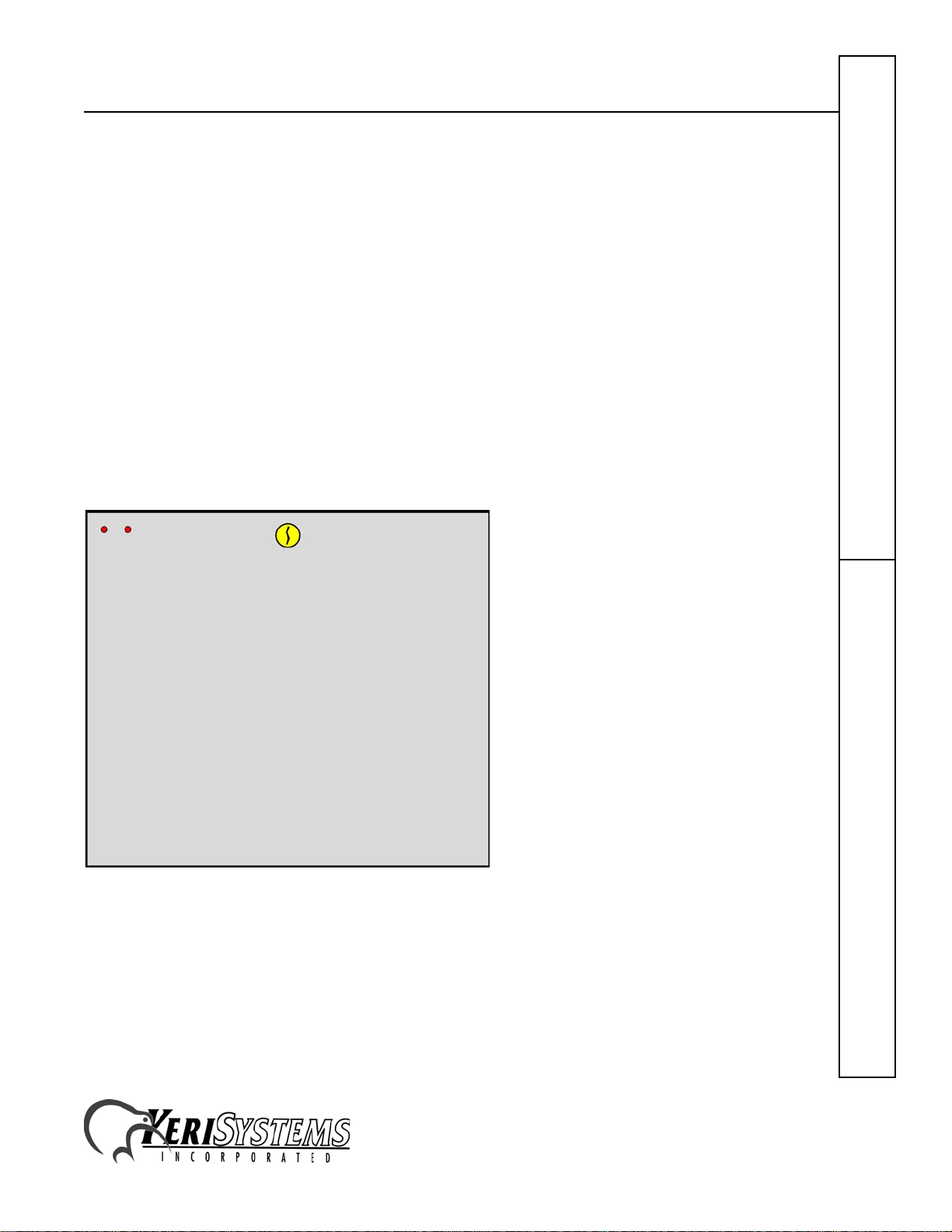
Eight-Door Concentrator
Keri Systems KDC-8 Eight-Door Concentrator places four controllers into one cabinet, reducing
the amount of space needed to mount four controllers. The concentrator is designed to fit in a
standard IT server/telecom rack, but can easily be wall mounted. There are knock-outs around the
outside of concentrator’s enclosure for cable routing.
1.0 Unit Specifications
• Height – 15 inches (plus 0.25 inches for the cover)
• Width – 17 inches (plus 0.25 inches for the cover)
• Depth – 6.5 inches (plus 0.25 inches for the cover)
• Weight – 19 pounds (including controllers and satellite boards, NOT including cabling)
• Power Requirements – 12 VDC @ 3 A for the concentrator cabinet, including four, two-door
controllers.
NOTE: Separately powered door lock power requirements depend upon the door locks being used.
Please ensure sufficient power is provided to support all door locks connected to the cabinet.
Figure 1: 8-Door Concentrator Enclosure
2.0 Mounting the Cabinet
There are three methods of cabinet mounting.
1. wall mounting through the rear of the cabinet
2. wall mounting using the rack brackets
3. rack mounting to a standard IT Server/Telecom rack
2305 Bering Drive 01959-001 Rev. 1.1
San Jose, CA 95131 USA
(800) 260-5265 (408) 435-8400 FAX (408) 577-1792
Web: http://www.kerisys.com E-mail: sales@kerisys.com Page 1 of 24
KDC-8Quick Start Guide
Page 2
Eight-Door Concentrator
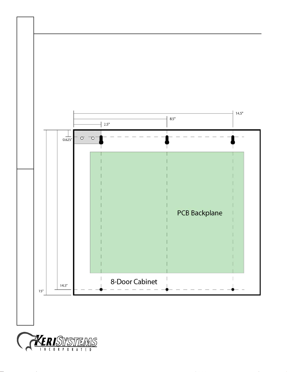
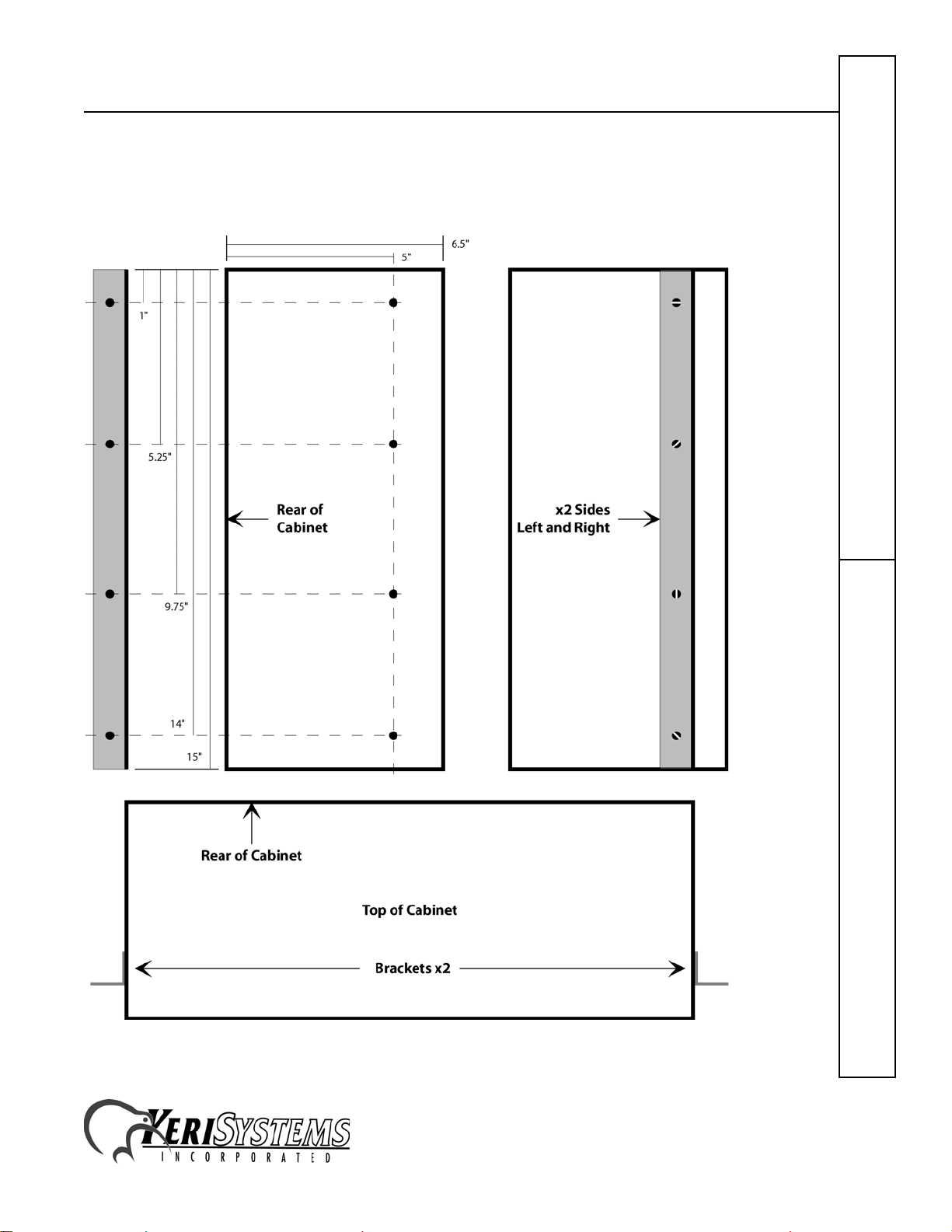
2.1 Through the Cabinet Mounting
The easiest mounting method is wall mounting through mounting holes within the cabinet. There
are three key-hole screw slots and three screw through-holes for secure mounting. Have an assistant
hold the unit in the desired mounting place and mark the mounting locations, see Figure 2 (if there
are controllers in the cabinet, please remove them before mounting the enclosure). Drill pilot holes
in the marked locations and then install the unit.
Note: When fully loaded, the unit weighs 19 pounds (before cabling). Mount the unit securely
against the wall using molly-bolts or by securing at least two mounting screws to a wall stud.
Quick Start GuideKDC-8
Figure 2: Through-the-Cabinet Mounting Dimensions
2305 Bering Drive 01959-001 Rev. 1.1
San Jose, CA 95131 USA
(800) 260-5265 (408) 435-8400 FAX (408) 577-1792
Web: http://www.kerisys.com E-mail: sales@kerisys.com Page 2 of 24
Page 3
Eight-Door Concentrator
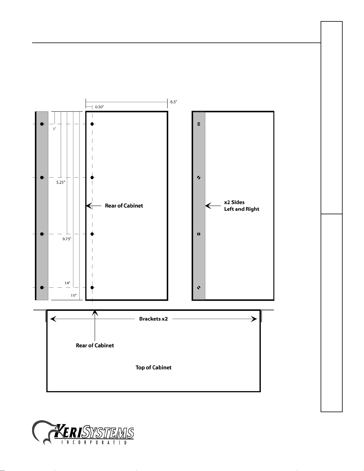
2.2 Bracket Wall Mounting
Attach the brackets to the rear of the cabinet sides (see Figure 3). Have an assistant hold the unit in
the desired mounting place and mark the mounting locations. Drill pilot holes in the marked
locations.
Figure 3: Attaching the Brackets to the Enclosure for Wall Mounting
2305 Bering Drive 01959-001 Rev. 1.1
San Jose, CA 95131 USA
(800) 260-5265 (408) 435-8400 FAX (408) 577-1792
Web: http://www.kerisys.com E-mail: sales@kerisys.com Page 3 of 24
KDC-8Quick Start Guide
Page 4
Eight-Door Concentrator
Have an assistant hold the unit in the desired mounting place and mark the mounting locations (see
Figure 4). Drill pilot holes in the marked locations and then install the unit.
Note: When fully loaded, the unit weighs 19 pounds (before cabling). Mount the unit securely
against the wall using molly-bolts or by securing at least two mounting screws to a wall stud.
Quick Start GuideKDC-8
Figure 4: Wall Mounting the Enclosure Using the Brackets
2305 Bering Drive 01959-001 Rev. 1.1
San Jose, CA 95131 USA
(800) 260-5265 (408) 435-8400 FAX (408) 577-1792
Web: http://www.kerisys.com E-mail: sales@kerisys.com Page 4 of 24
Page 5
Eight-Door Concentrator
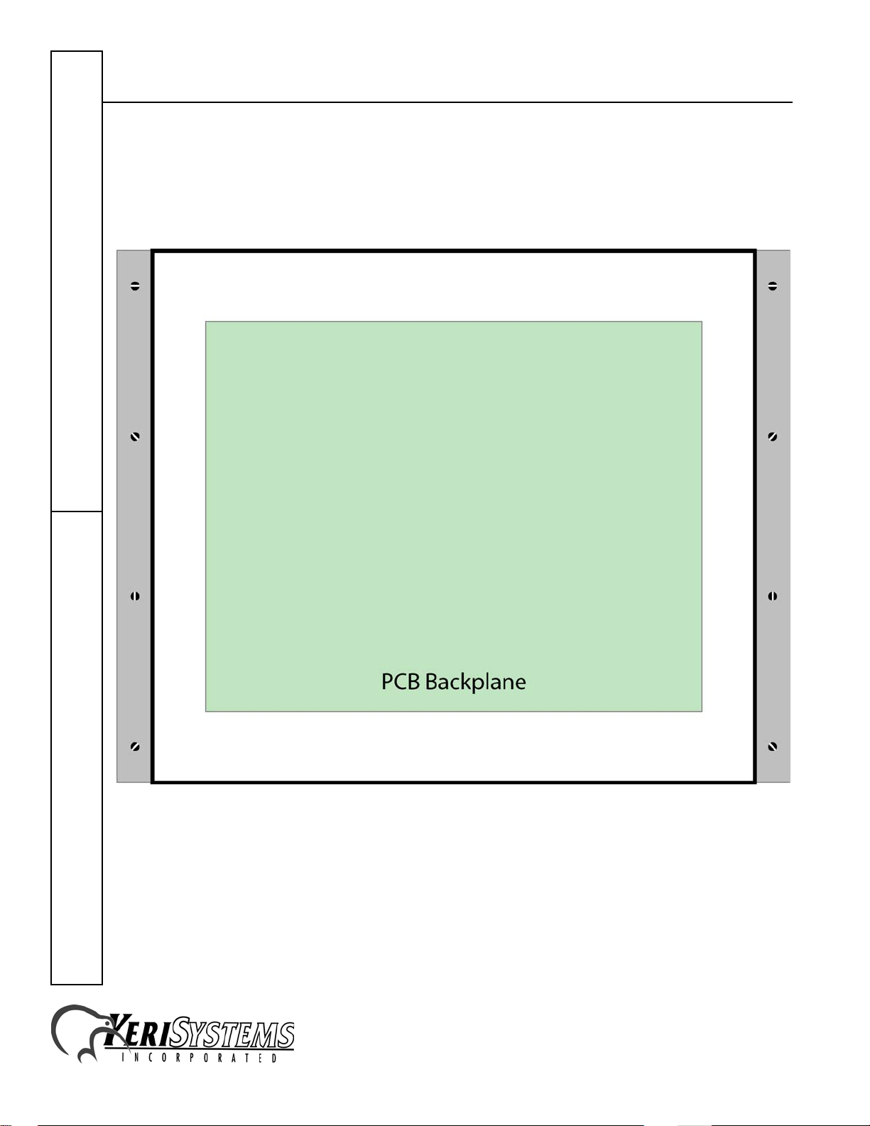
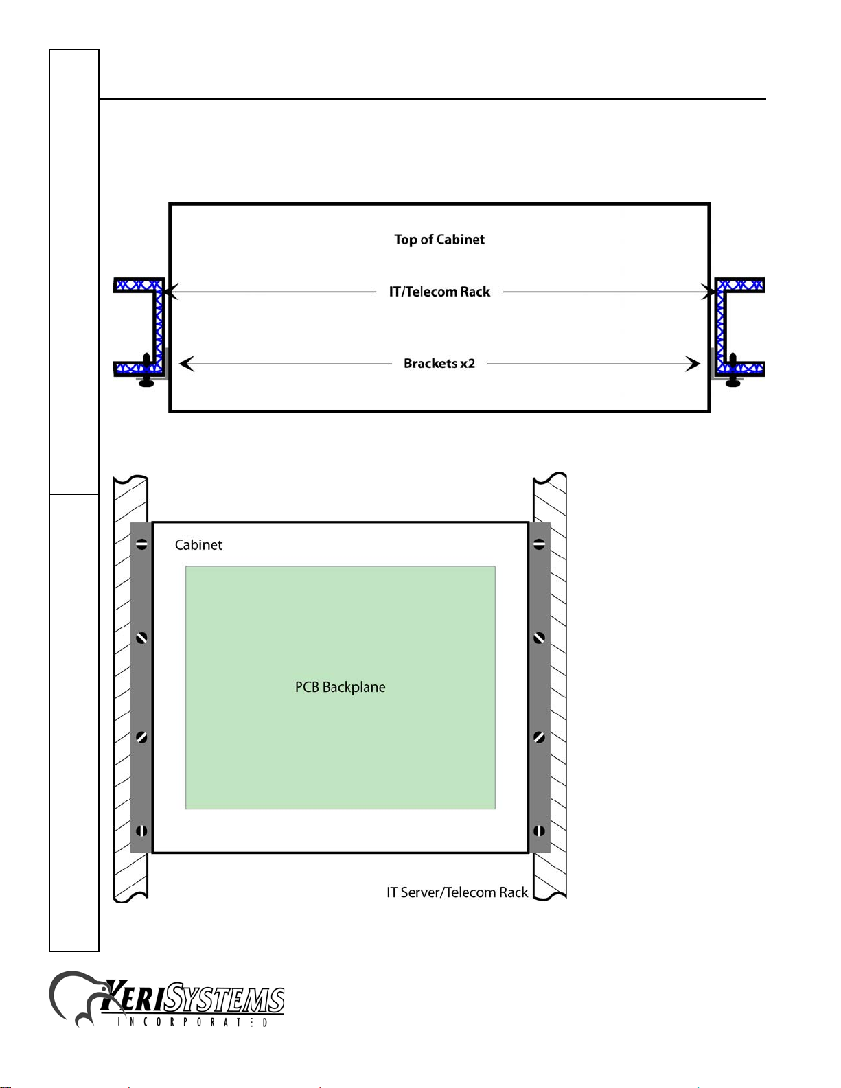
2.3 Rack Mounting
The cabinet is designed to be installed in a standard IT Server/Telecom rack using the two rackmount brackets. Attach the brackets to the sides of the cabinet (see Figure 5).
Figure 5: Attaching the Brackets to the Enclosure for Rack Mounting
2305 Bering Drive 01959-001 Rev. 1.1
San Jose, CA 95131 USA
(800) 260-5265 (408) 435-8400 FAX (408) 577-1792
Web: http://www.kerisys.com E-mail: sales@kerisys.com Page 5 of 24
KDC-8Quick Start Guide
Page 6
Eight-Door Concentrator
Have an assistant hold the cabinet in the desired mounting place on the rack and secure the cabinet
using the rack mount screws (see Figure 6 and Figure 7 – a generic rack configuration is shown,
your rack may be slightly different).
Figure 6: Attaching the Unit to the Rack - Top View
Quick Start GuideKDC-8
Figure 7: Attaching the Unit to the Rack - Front View
2305 Bering Drive 01959-001 Rev. 1.1
San Jose, CA 95131 USA
(800) 260-5265 (408) 435-8400 FAX (408) 577-1792
Web: http://www.kerisys.com E-mail: sales@kerisys.com Page 6 of 24
Page 7

Eight-Door Concentrator
3.0 Configuration and Wiring
It takes a lot of cabling to support all eight doors in the cabinet. Knockouts are provided on all four
sides, cabinet providing maximum flexibility for routing cables.
Cabinet configuration is kept simple. The only jumpers of which to be aware are the external door
lock power jumpers, and there are two front-cover LED cables.
3.1 External Door Lock Relays
The 8-door cabinet is designed to allow the door lock relays to operate in two ways.
1. Non-powered/dry-contact for use with devices such as a gate operator or as a non-powered
general purpose output.
2. Powered through the lock relay common for electric door locks. The unit can use one power
supply to drive both the controllers and the lock relays, or have separate power supplies, one for
the controllers and one for the door lock relays.
Each door lock relay can be set according to your application: non-powered/dry-contact or powered
for an electric door lock.
NOTE: When providing power for door lock relays, Keri strongly recommends using two separate
power supplies. This isolates controller power from the transients that can be created on the lock
power line as the door relays kick on and off. This will reduce controller interference.
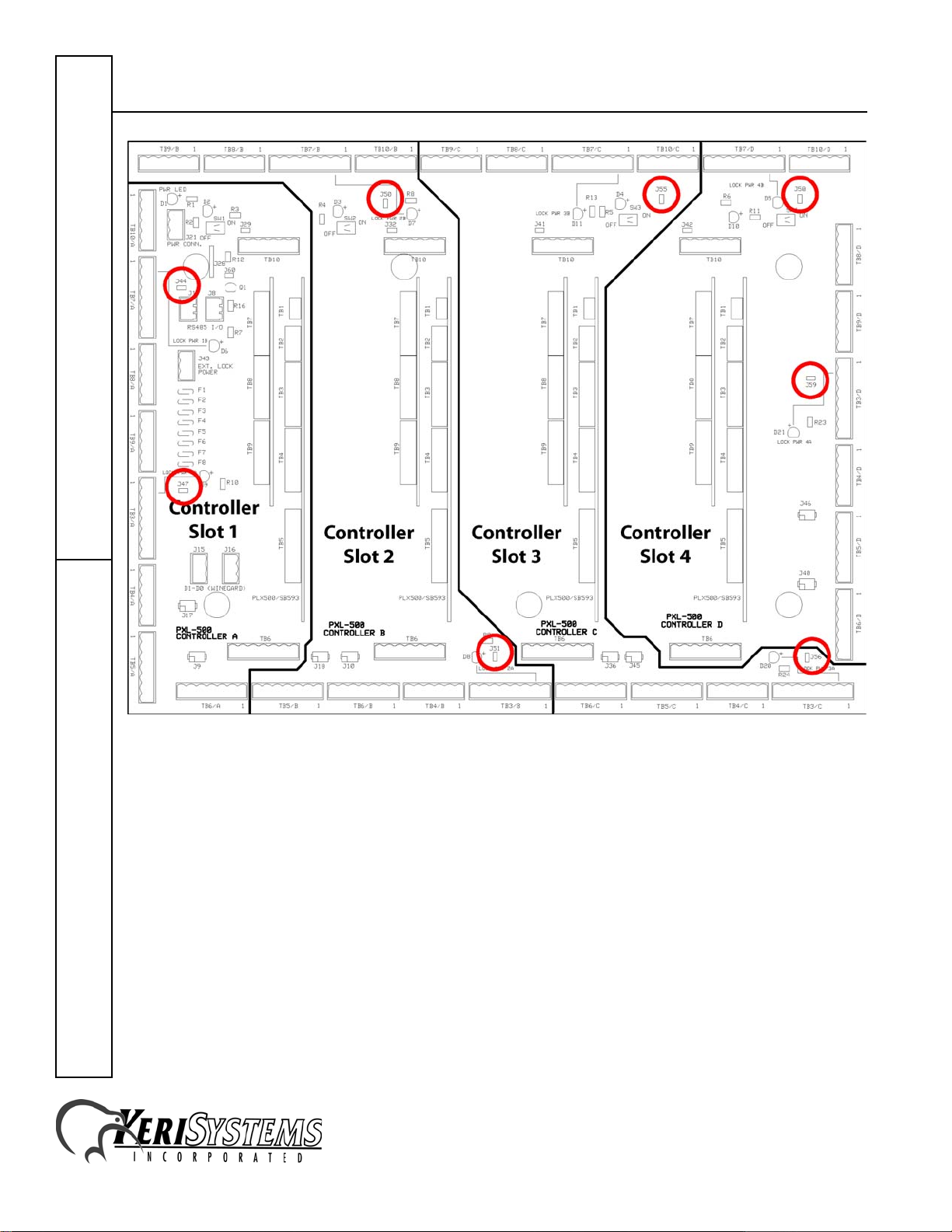
The factory default is to have the following jumpers set per Table 1, allowing the use of external
lock power through the relay common. Refer to Figure 8 on page 8 for jumper locations.
Jumpers listed in Table 1 must be removed for any controller/satellite board relays used in nonpowered/dry-contact mode or in non-powered, general purpose output mode.
Table 1: External Door Lock Power
Jumpers
Controller A-Door B-Door
Slot 1 J47 J44
Slot 2 J51 J50
Slot 3 J56 J55
Slot 4 J59 J58
KDC-8Quick Start Guide
2305 Bering Drive 01959-001 Rev. 1.1
San Jose, CA 95131 USA
(800) 260-5265 (408) 435-8400 FAX (408) 577-1792
Web: http://www.kerisys.com E-mail: sales@kerisys.com Page 7 of 24
Page 8
Eight-Door Concentrator
Quick Start GuideKDC-8
Figure 8: External Door Lock Power Jumpers
2305 Bering Drive 01959-001 Rev. 1.1
San Jose, CA 95131 USA
(800) 260-5265 (408) 435-8400 FAX (408) 577-1792
Web: http://www.kerisys.com E-mail: sales@kerisys.com Page 8 of 24
Page 9

Eight-Door Concentrator
3.2 Cabinet Cover Power LED
The cabinet cover Power LED cable is connected at the factory. It is the left LED on the face of the
cabinet (see Figure 1 on page 1). Should the cable come free, connect the cable to J28 pins 1 and 2
with the RED wire connected to pin 1. Refer to Figure 9.
3.3 Cabinet Cover Data LED
The cabinet cover Data LED cable is connected at the factory. It is the right LED on the face of the
cabinet (see Figure 1 on page 1). Should the cable come free, connect the cable to J60 pins 1 and 2
with the RED wire connected to pin 1. Refer to Figure 9.
Figure 9: Power and Data Cover LED Cabling
2305 Bering Drive 01959-001 Rev. 1.1
San Jose, CA 95131 USA
(800) 260-5265 (408) 435-8400 FAX (408) 577-1792
Web: http://www.kerisys.com E-mail: sales@kerisys.com Page 9 of 24
KDC-8Quick Start Guide
Page 10

Eight-Door Concentrator
3.4 Individual Controller Wiring Connections
Around the perimeter of the PCB is a ring of 32 connectors. Each connector on the four controllers/
satellite boards has a corresponding connector on the perimeter ring – eight connectors for each
controller/satellite board. Figure 10 shows the location of the connector set for each controller/
satellite board.
Quick Start GuideKDC-8
Figure 10: Connnector Set per Controller/Satellite Board
2305 Bering Drive 01959-001 Rev. 1.1
San Jose, CA 95131 USA
(800) 260-5265 (408) 435-8400 FAX (408) 577-1792
Web: http://www.kerisys.com E-mail: sales@kerisys.com Page 10 of 24
Page 11

Eight-Door Concentrator
3.4.1 A-Reader, B-Reader (TB5 and TB6)
Controllers will either be Keri Proximity (PXL-500P - see Figure 11) or Wiegand (PXL-500W Figure 12). Make the wiring connections from the Reader to the appropriate connector accordingly:
A-Reader to TB5, B-Reader to TB6. Use Figure 10 on page 10 to locate the correct connector
locations for each controller.
Figure 11: Proximity A-Reader and B-Reader Connections (TB5 and TB6)
Figure 12: Wiegand A-Reader and B-Reader Connections (TB5 and TB6)
KDC-8Quick Start Guide
2305 Bering Drive 01959-001 Rev. 1.1
San Jose, CA 95131 USA
(800) 260-5265 (408) 435-8400 FAX (408) 577-1792
Web: http://www.kerisys.com E-mail: sales@kerisys.com Page 11 of 24
Page 12

Eight-Door Concentrator
3.4.2 A-Door: Lock Relay, Alarm Relay Outputs (TB3)
Make the wiring connections for the A-Door Lock and Alarm Relays (TB3). Use Figure 10 on
page 10 to locate the correct connectors for each controller.
For the Lock Relay, power is applied to the common line. This provides flexibility, allowing you to
provide power to the lock depending upon the type of lock you have.
Quick Start GuideKDC-8
Figure 13: A-Door Lock Relay and Alarm Relay Connections (TB3)
2305 Bering Drive 01959-001 Rev. 1.1
San Jose, CA 95131 USA
(800) 260-5265 (408) 435-8400 FAX (408) 577-1792
Web: http://www.kerisys.com E-mail: sales@kerisys.com Page 12 of 24
Page 13

Eight-Door Concentrator
3.4.3 B-Door: Lock Relay, Alarm Relay,
General Purpose Outputs 1 and 2 (TB7)
TB7 can serve one of two purposes depending upon the configuration of the controller’s satellite
board: as the B-Door Lock Relay and Alarm Relay OR as general purpose outputs 1 and 2. Make
the wiring connections for either Lock/Alarm Relay usage or for general purpose outputs (TB7).
Use Figure 10 on page 10 to locate the correct connectors for each controller.
For the Lock Relay, power is applied to the common line. This provides flexibility, allowing you to
provide power to the lock depending upon the type of lock you have.
NOTE: If the controller is configured for TB1 general purpose output 1 operation, the
corresponding door lock relay jumper may need to be removed (see Table 1 on page 7 for jumper
identification). Remove the jumper for non-powered/dry-contact operation; leave the jumper in
place for powered operation.
Figure 14: B-Door Lock Relay and Alarm Relay Connections
Figure 15: General Purpose Output 1 and 2 Connections (TB7)
2305 Bering Drive 01959-001 Rev. 1.1
San Jose, CA 95131 USA
(800) 260-5265 (408) 435-8400 FAX (408) 577-1792
Web: http://www.kerisys.com E-mail: sales@kerisys.com Page 13 of 24
KDC-8Quick Start Guide
Page 14

Eight-Door Concentrator
3.4.4 A and B-Door Held Open Outputs,
General Purpose Outputs 3 and 4 (TB10)
TB10 can serve one of two purposes depending upon the configuration of the controller’s satellite
board: as the A and B Door Held Open Outputs OR as general purpose outputs 3 and 4. Make the
wiring connections for either Door Held Open Relay usage or for general purpose outputs as
required. Use Figure 10 on page 10 to locate the correct connectors for each controller.
Quick Start GuideKDC-8
Figure 16: A and B Door Held Open Outputs
Figure 17: General Purpose Outputs 3 and 4
NOTE: When wired correctly, all door held open outputs can provide voltage to drive an external
device.
2305 Bering Drive 01959-001 Rev. 1.1
San Jose, CA 95131 USA
(800) 260-5265 (408) 435-8400 FAX (408) 577-1792
Web: http://www.kerisys.com E-mail: sales@kerisys.com Page 14 of 24
Page 15

Eight-Door Concentrator
3.4.5 A-Door: Status Switch, Request to Exit, Auxiliary Request to Exit,
Global Unlock Inputs (TB4)
Make the wiring connections for the A-Door Status Switch and Request to Exit inputs (TB4). Use
Figure 10 on page 10 to locate the correct connectors for each controller.
On the master controller, the final input on TB4 can serve one of two purposes. It can either act as
an Auxiliary Request to Exit for the A-Door or as a Global Unlock for the access control system.
For the master controller, determine if your site requires a Global Unlock input or if you need the
Auxiliary Request to Exit input, and make the appropriate wiring connection.
For all other controllers, the final input can only be used as an Auxiliary Request to Exit for the ADoor. Make the Auxiliary Request to Exit connection if required.
Figure 18: A-Door: Status Switch, Request to Exit, Auxiliary Request to Exit, Global Unlock
Inputs (TB4)
2305 Bering Drive 01959-001 Rev. 1.1
San Jose, CA 95131 USA
(800) 260-5265 (408) 435-8400 FAX (408) 577-1792
Web: http://www.kerisys.com E-mail: sales@kerisys.com Page 15 of 24
KDC-8Quick Start Guide
Page 16

Eight-Door Concentrator
3.4.6 B-Door: Status Switch, Request to Exit, Auxiliary Request to Exit,
General Purpose Input 4 (TB8)
Make the wiring connections for the B-Door Status Switch, Request to Exit, and Auxiliary Request
to Exit inputs (TB8). Make the general purpose input 4 connection if required. Use Figure 10 on
page 10 to locate the correct connectors for each controller.
Quick Start GuideKDC-8
Figure 19: B-Door: Status Switch, Request to Exit, Auxiliary Request to Exit,
General Purpose Input 4 (TB8)
2305 Bering Drive 01959-001 Rev. 1.1
San Jose, CA 95131 USA
(800) 260-5265 (408) 435-8400 FAX (408) 577-1792
Web: http://www.kerisys.com E-mail: sales@kerisys.com Page 16 of 24
Page 17

Eight-Door Concentrator
3.4.7 General Purpose Inputs 5, 6, 7, 8 (TB9)
Make the general purpose input 5, 6, 7, and 8 connections if required (TB9). Use Figure 10 on
page 10 to locate the correct connectors for each controller.
Figure 20: General Purpose Inputs 5, 6, 7, and 8
KDC-8Quick Start Guide
2305 Bering Drive 01959-001 Rev. 1.1
San Jose, CA 95131 USA
(800) 260-5265 (408) 435-8400 FAX (408) 577-1792
Web: http://www.kerisys.com E-mail: sales@kerisys.com Page 17 of 24
Page 18

Eight-Door Concentrator
3.5 RS-485 Network
J1 and J8 allow you to daisy-chain the RS-485 access control network (see Figure 21). Connect the
incoming RS-485 line to J1 and connect the outgoing RS-485 line to J8 (see Figure 22).
Quick Start GuideKDC-8
Figure 21: Location of RS-485 Network Connectors
Figure 22: RS-485 In/Out Lines
2305 Bering Drive 01959-001 Rev. 1.1
San Jose, CA 95131 USA
(800) 260-5265 (408) 435-8400 FAX (408) 577-1792
Web: http://www.kerisys.com E-mail: sales@kerisys.com Page 18 of 24
Page 19

Eight-Door Concentrator
3.6 External Door Lock Power
J43 provides the external door lock power (see Figure 23). Connect the line from the power supply
to J43 (see Figure 24). Power can be from an independent power supply or can be daisy-chained
from the controller/cabinet power supply (Section 3.7 on page 20). Power is provided to the relays
through the lock relay common line.
NOTE: When providing power for door lock relays, Keri strongly recommends using two separate
power supplies. This isolates controller power from the transients that can be created as the door
relays kick on and off.
Figure 23: Location of Lock Power Connector
Figure 24: Lock Power Wiring
2305 Bering Drive 01959-001 Rev. 1.1
San Jose, CA 95131 USA
(800) 260-5265 (408) 435-8400 FAX (408) 577-1792
Web: http://www.kerisys.com E-mail: sales@kerisys.com Page 19 of 24
KDC-8Quick Start Guide
Page 20

Eight-Door Concentrator
3.7 Cabinet Power
J21 provides power to the controllers (see Figure 25). Connect the line from the controller power
supply to J21 (see Figure 26).
Quick Start GuideKDC-8
Figure 25: Location of Controller Power Connector
Figure 26: Controller Power Wiring
2305 Bering Drive 01959-001 Rev. 1.1
San Jose, CA 95131 USA
(800) 260-5265 (408) 435-8400 FAX (408) 577-1792
Web: http://www.kerisys.com E-mail: sales@kerisys.com Page 20 of 24
Page 21

Eight-Door Concentrator
4.0 Inserting PCBs
The concentrator backplane is now ready for the four controllers/satellite boards. To insert a
controller into the backplane, carefully align the connectors on the controller with the plugs on the
backplane and slide the controller into place. It will be a firm, snug connection.
Once all four controllers are installed, connect the four Reader Jumper cables (provided with the
cabinet). These cables connect the B-Reader on the controller to the backplane.
Next, connect the TB10 Relay Jumper cables (provided with the cabinet). These cables connect
TB10 on the satellite board to the backplane.
Figure 27: B-Reader and TB10 Backplane Connection Locations
2305 Bering Drive 01959-001 Rev. 1.1
San Jose, CA 95131 USA
(800) 260-5265 (408) 435-8400 FAX (408) 577-1792
Web: http://www.kerisys.com E-mail: sales@kerisys.com Page 21 of 24
KDC-8Quick Start Guide
Page 22

Eight-Door Concentrator
4.1 B-Reader Jumper Cables
Four sets are provided with the concentrator. These cables connect the individual controller BReader connections to the concentrator. This wiring diagram is provided should a reader jumper
cable be lost.
Quick Start GuideKDC-8
Figure 28: B-Reader Jumper Cable Wiring
4.2 TB10 Relay Output Jumper Cables
Four sets are provided with the concentrator. These cables connect the individual controller TB10
connections to the concentrator. This wiring diagram is provided should a TB10 jumper cable be
lost.
Figure 29: TB10 Jumper Cable Wiring
2305 Bering Drive 01959-001 Rev. 1.1
San Jose, CA 95131 USA
(800) 260-5265 (408) 435-8400 FAX (408) 577-1792
Web: http://www.kerisys.com E-mail: sales@kerisys.com Page 22 of 24
Page 23

Eight-Door Concentrator
5.0 Cabinet Operation
5.1 Powering ON the Controllers
Near the top of each controller is a power switch and a power ON LED. This provides maximum
flexibility in powering up the unit and in swapping boards. When ready, simply switch ON each
controller, one-at-a-time, and verify power on by both the backplane power ON LED and the
controller’s own power LED.
Lock power ON is signified by a separate set of LEDs, one for each lock relay. These LEDs will be
ON when lock power is being supplied to the lock relay through the lock jumpers.
Figure 30: Lock Power LED Locations
2305 Bering Drive 01959-001 Rev. 1.1
San Jose, CA 95131 USA
(800) 260-5265 (408) 435-8400 FAX (408) 577-1792
Web: http://www.kerisys.com E-mail: sales@kerisys.com Page 23 of 24
KDC-8Quick Start Guide
Page 24

Eight-Door Concentrator
5.2 Closing the Cabinet
The Concentrator cabinet cover has a slip-hinge that allows you to completely remove the cover
when working inside the unit. It has a single lock that provides cabinet security.
5.3 Front Cover LEDs
There are two LEDs in the upper-left corner of the unit, visible through the cabinet cover.
• The left LED is for controller power ON.
• The right LED is for network communication activity.
Quick Start GuideKDC-8
2305 Bering Drive 01959-001 Rev. 1.1
San Jose, CA 95131 USA
(800) 260-5265 (408) 435-8400 FAX (408) 577-1792
Web: http://www.kerisys.com E-mail: sales@kerisys.com Page 24 of 24
 Loading...