

Page 1

Doors NetXtreme
Access Control Software
Reference Manual v4.0
(P/N 01945-100)
™
Page 2

© 1998-2008 Keri Systems, Inc. – ALL RIGHTS RESERVED
Document Number 01945-100, Revision 4.0 – December 2008
Keri Systems, Doors NetXtreme, and DoorsNXT are trademarks of Keri Systems, Inc.
Acrobat® Reader © 1987-2007 Adobe Systems Incorporated. All rights reserved. Adobe and Acrobat are
trademarks of Adobe Systems, Incorporated.
Windows is a trademark of Microsoft Corporation.
The trademarks used in this Reference Manual are the property of the trademark holders. The use of these
trademarks in this Reference Manual should not be regarded as infringing upon or affecting the validity of these
trademarks.
Keri Systems, Inc. reserves the right to change, without notice, product offerings or specifications.
No part of this publication may be reproduced in any form without written permission from Keri Systems, Inc.
Page 3

Keri Systems, Inc. Doors NetXtreme™ Reference Manual
Doors NetXtreme
TM
Reference Manual
Table of Contents
Introduction to Doors NetXtreme . . . . . . . . . . . . . . . . . . . . . . . . . . . . . . . . . . . . . . . . . . . . . . . 3
Getting Started. . . . . . . . . . . . . . . . . . . . . . . . . . . . . . . . . . . . . . . . . . . . . . . . . . . . . . . . . . .
Software Installation . . . . . . . . . . . . . . . . . . . . . . . . . . . . . . . . . . . . . . . . . . . . . . . . . . . . . 4
Setup Client . . . . . . . . . . . . . . . . . . . . . . . . . . . . . . . . . . . . . . . . . . . . . . . . . . . . . . . . . . .
Log On to DoorsNXT . . . . . . . . . . . . . . . . . . . . . . . . . . . . . . . . . . . . . . . . . . . . . . . . . . . . 6
Setup System Information Page. . . . . . . . . . . . . . . . . . . . . . . . . . . . . . . . . . . . . . . . . . . . . 7
Tutorials . . . . . . . . . . . . . . . . . . . . . . . . . . . . . . . . . . . . . . . . . . . . . . . . . . . . . . . . . . . . . .
Setup Options and Preferences . . . . . . . . . . . . . . . . . . . . . . . . . . . . . . . . . . . . . . . . . . . . . . . . . 9
Setup Security and Licensing. . . . . . . . . . . . . . . . . . . . . . . . . . . . . . . . . . . . . . . . . . . . . . . 9
Setup User Defined Fields . . . . . . . . . . . . . . . . . . . . . . . . . . . . . . . . . . . . . . . . . . . . . . . . 10
Setup Database Backup Path . . . . . . . . . . . . . . . . . . . . . . . . . . . . . . . . . . . . . . . . . . . . . . 10
Badging . . . . . . . . . . . . . . . . . . . . . . . . . . . . . . . . . . . . . . . . . . . . . . . . . . . . . . . . . . . . .
Operators . . . . . . . . . . . . . . . . . . . . . . . . . . . . . . . . . . . . . . . . . . . . . . . . . . . . . . . . . . . . .
Create a New Security Level . . . . . . . . . . . . . . . . . . . . . . . . . . . . . . . . . . . . . . . . . . . . . . 12
Security Level Rights . . . . . . . . . . . . . . . . . . . . . . . . . . . . . . . . . . . . . . . . . . . . . . . . 13
Create a New Operator. . . . . . . . . . . . . . . . . . . . . . . . . . . . . . . . . . . . . . . . . . . . . . . . . . . 15
Setup Geographical Timezones . . . . . . . . . . . . . . . . . . . . . . . . . . . . . . . . . . . . . . . . . . . . 16
Networking . . . . . . . . . . . . . . . . . . . . . . . . . . . . . . . . . . . . . . . . . . . . . . . . . . . . . . . . . . .
Location and Subnet Configuration . . . . . . . . . . . . . . . . . . . . . . . . . . . . . . . . . . . . . . . . . 17
Firewall and Network Security . . . . . . . . . . . . . . . . . . . . . . . . . . . . . . . . . . . . . . . . . . . . 18
AutoConfig . . . . . . . . . . . . . . . . . . . . . . . . . . . . . . . . . . . . . . . . . . . . . . . . . . . . . . . . . . .
Verify Controller Configuration . . . . . . .
Setup System Timezones & Holidays. . . . . . . . . . . . . . . . . . . . . . . . . . . . . . . . . . . . . . . . . . . 22
System Timezones . . . . . . . . . . . . . . . . . . . . . . . . . . . . . . . . . . . . . . . . . . . . . . . . . . . . . . 22
Graveyard Shift Time Zone Example
Holidays Tab . . . . . . . . . . . . . . . . . . . . . . . . . . . . . . . . . . . . . . . . . . . . . . . . . . . . . . . . . . .
Create and Assign Property Sets . . . . . . . . . . . . . . . . . . . . . . . . . . . . . . . . . . . . . . . . . . . . . . . 25
Doors/Gates Property Sets . . . . . .
Standard Doors/Gates Properties . . . .
Create a New Doors/Gates Property Set . . . . . . . . . . . . . . . . . . . . . . . . . . . . . . . . . 27
Configure Input Property Sets . .
Configure Output Property Sets . . . . . . . . . . . . . . . . . . . . . . . . . . . . . . . . . . . . . . . . 29
Create Sites and Groups . . . . . . . . . . . . . . . . . . . . . . . . . . . . . . . . . . . . . . . . . . . . . . 30
Create New Site . . . . . . . . . . . . . . . . . . . . . . . . . . . . . . . . . . . . . . . . . . . . . . . . . 30
Create New Group . . . . . . . . . . . . . . . . . . . . . . . . . . . . . . . . . . . . . . . . . . . . . . . 30
Assign Property Sets to Controllers . .
Assign Doors/Gates Property Set . . . . . . . . . . . . . . . . . . . . . . . . . . . . . . . . . . . . . . 31
Assign Inputs Property Set . . . . . . . . . . . . . . . . . . . . . . . . . . . . . . . . . . . . . . . . . . . 32
Assign Outputs Property Set . . . . . . . . . . . . . . . . . . . . . . . . . . . . . . . . . . . . . . . . . . 33
Assign Reader Type . . . . . . . . . . . . . . . . . . . . . . . . . . . . . . . . . . . . . . . . . . . . . . . . . 34
Create New Trigger (I/O) Action Sequence . . . . . . . . . . . . . . . . . . . . . . . . . . . . . . . . . . 35
. . . . . . . . . . . . . . . . . . . . . . . . . . . . . . . . . . . . 21
(Cros
sing Midnight) . . . . . . . . . . . . . . . . . . 23
. . . . . . . . . . . . . . . . . . . . . . . . . . . . . . . . . . . . . . . . . . 25
. . . . . . . . . . . . . . . . . . . . . . . . . . . . . . . . . . . 26
. . . . . . . . . . . . . . . . . . . . . . . . . . . . . . . . . . . . . . . 29
.
. . . . . . . . . . . . . . . . . . . . . . . . . . . . . . . . . . . . . . 31
. . . 4
. 4
. 8
.
11
. . . . 12
. .
. . 17
. .
. . 19
. . . 24
01945-100 Rev. 4.0 Table of Contents Page 1
Page 4

Doors NetXtreme™ Reference Manual Keri Systems, Inc.
. . . . 53
.
. . . . 59
. . .
62
37
41
43
48
52
56
68
Setup Access Group . . . . . . . . . . . . . . . . . . . . . . . . . . . . . . . . . . . . . . . . . . . . . . . . . . . . . . . .
Credential and User Enrollment . . . . . . . . . . . . . . . . . . . . . . . . . . . . . . . . . . . . . . . . . . . . . . . 38
Enroll Credentials . . . . . . . . . . . . . . . . . . . . . . . . . . . . . . . . . . . . . . . . . . . . . . . . . . . . . . 38
Enroll Credentials - Block Enrollment . . . . . . . . . . . . . . . . . . . . . . . . . . . . . . . . . . 38
Enroll Credentials - Learn Mode . . . . . . . . . . . . . . . . . . . . . . . . . . . . . . . . . . . . . . . 39
Enroll Credentials - PIN (Personal
Enroll Users . . . . . . . . . . . . . . . . . . . . . . . . . . . . . . . . . . . . . . . . . . . . . . . . . . . . . . . . . . .
Assign Credentials to Users . . . . . . . . .
IN / OUT Reader. . . . . . . . . . . . . . . . . . . . . . . . . . . . . . . . . . . . . . . . . . . . . . . . . . . . . . . . . . .
Enable In/Out Reader. . . . . . . . . . . . . . . . . . . . . . . . . . . . . . . . . . . . . . . . . . . . . . . . . . . . 43
Create In/Out Reader Property Set. . . . . .
Assign Property Set To In/Out Reader . .
Create In/Out Reader Action Sequence . . . . . . . . . . . . . . . . . . . . . . . . . . . . . . . . . . . . . . 46
Create In/Out Reader Access Group . . . . . . . . . . . . . . .
Update the Network . . . . . . . . . . . . . . . . . . . . . . . . . . . . . . . . . . . . . . . . . . . . . . . . . . . . . . . .
Collect Events From the Network. . . . . . . . . . . . . . . . . .
Flash Upgrade Controllers/Devices . . . . . . . . . . . . . . . . . . . . . . . . . . . . . . . . . . . . . . . . . . . . 50
Reset Controllers Remotely Through DoorsNXT. . . . . . . . .
Operate Hardware . . . . . . . . . . . . . . . . . . . . . . . . . . . . . . . . . . . . . . . . . . . . . . . . . . . . . . . . . .
Monitor . . . . . . . . . . . . . . . . . . . . . . . . . . . . . . . . . . . . . . . . . . . . . . . . . . . . . . . . . . . . . .
Setup Monitor View Filters . . . . . . . . . . . . . . . . . . . . . . . . . . . . . . . . . . . . . . . . . . . . . . . 53
Setup Event Messages . . . . . . . . . . . . . . . . . . . . . . . . . . . . . . . . . . . . . . . . . . . . . . . . . . . 54
Show Photo . . . . . . . . . . . . . . . . . . . . . . . . . . . . . . . . . . . . . . . . . . . . . . . . . . . . . . . . . . . 55
Enable Show Photo . . . . . . . . . . . . . . . . . . . . . . . . . . . . . . . . . . . . . . . . . . . . . . . . . 55
Show Photo in Setup Users Window . . . . . . . . . . . . . . . . . . . . . . . . . . . . . . . . . . . . 55
System Diagnostics . . . . . . . . . . . . . . . . . . . . . . . . . . . . . . . . . . . . . . . . . . . . . . . . . . . . . . . .
System Diagnostics - Modules. . . . . . . . . . . . . . . . . . . . . . . . . . . . . . . . . . . . . . . . . . . . . 57
System Diagnostics - Inputs. . . . . . . . . . . . . . . . . . . . . . . . . . . . . . . . . . . . . . . . . . . . . . . 57
System Diagnostics - Relays . . . . . . . . . . . . . . . . . . . . . . . . . . . . . . . . . . . . . . . . . . . . . . 58
System Diagnostics - Doors. . . . . . . . . . . . . . . . . . . . . . . . . . . . . . . . . . . . . . . . . . . . . . . 58
Reporting. . . . . . . . . . . . . . . . . . . . . . . . . . . . . . . . . . . . . . . . . . . . . . . . . . . . . . . . . . . . .
Run Pre-Designed Report . . . . . . . . . . . . . . . . . . . . . . . . . . . . . . . . . . . . . . . . . . . . . . . . 59
Create/Edit Reports . . . . . . . . . . . . . . . . . . . . . . . . . . . . . . . . . . . . . . . . . . . . . . . . . . . . . 61
Dual Verification. . . . . . . . . . . . . . . . . . . . . . . . . . . . . . . . . . . . . . . . . . . . . . . . . . . . . . . .
Enable Dual Verification . . . . . . . . . . . . . . . . . . . . . . . . . . . . . . . . . . . . . . . . . . . . . . . . . 62
Create Dual Verification Property Set .
Assign Dual Verification Property Set and R
Create Dual Verification Action Sequence
Create Dual Verification Access Group. . .
Create Standard Access Group on Dual Verification Door .
Update the Network . . . . . . . . . . . . . . . . . . . . . . . . . . . . . . . . . . . . . . . . . . . . . . . . . . . . . 67
Enroll Primary and Secondary Credentials
Enroll Users . . . . . . . . . . . . . . . . . . . . . . . . . . . . . . . . . . . . . . . . . . . . . . . . . . . . . . . . . . .
Assign Primary and Secondary Credentials To Users
Identification Number)
. . . . . . . . . . . . . . . . . . . . . . . . . . . . . . . . . . . . . . 42
. . . . . . . . . . . . . . . . . . . . . . . . . . . . . . . . . . . . 44
. . . . . . . . . . . . . . . . . . . . . . . . . . . . . . . . . . . . 45
. . . . . . . . . . . . . . . . . . . . . . . . . 47
. . . . . . . . . . . . . . . . . . . . . . . . . . . . 49
. . . . . . . . . . . . . . . . . . . . . . . . . 51
. . . . . . . . . . . . . . . . . . . . . . . . . . . . . . . . . . . . . . 63
eader(s) . . . . . . . . . . . . . . . . . . . . . . . . . . . 64
. . . . . . . . . . . . . . . . . . . . . . . . . . . . . . . . . . . 65
. . . . . . . . . . . . . . . . . . . . . . . . . . . . . . . . . . . 66
. . . . . . . . . . . . . . . . . . . . . . . . . . . . . . . . . . . 68
. . . . . . . . . . . . . . . . . . . . . . . . . . . 68
. . . . . . . . . . . . . . . . . . 40
. . . . . . . . . . . . . . . . . . 67
End of Section.
Page 2 Table of Contents 01945-100 Rev. 4.0
Page 5

Keri Systems, Inc. Doors NetXtremeTM Reference Manual
1.0 Introduction to Doors NetXtreme
Doors NetXtreme (DoorsNXT) is versatile in that it will work within a small LAN with a single PC
running the Server, Database and Client or within a Global WAN encompassing dozens of clients
controlling thousands of doors.
Doors NetXtreme operates in a networked client/server environment. There are four basic components
to the DoorsNXT architecture: NXT controller hardware, DoorsNXT server, DoorsNXT database, and
DoorsNXT client (referred throughout this document as the controller, server, database, and client.
NXT controller hardware may be comprised of a combination of 2-door and 4-door NXT controller
hardware, NXT 4x4 modules, Reader Interface Modules (RIM), and card readers (MS, Wiegand, and
NXT).
DoorsNXT Server is the workhorse of Doors NetXtreme. It manages the communication between the
clients and the NXT hardware.
DoorsNXT Database is SQL compliant, client/server software providing access from multiple
concurrent sites with no third-party royalty fees. The database is automatically installed on the same
computer as the server.
DoorsNXT Client provides an interface to configure the NXT hardware, operators, users, and access
control functionality. The client is secured by an operator login. It communicates to the server over
TCP/IP.
Configuration of DoorsNXT will require some general knowledge of TCP/IP Networking and will
require specific knowledge of network details of the system to which DoorsNXT will be installed.
The following information must be known before attempting to install and configure DoorsNXT:
• The MAC address of the NXT hardware to be installed.
• The IP Addresses that will be assigned to the NXT controllers (each controller
own IP Address).
• The Subnet mask to be used for the LAN segment where the controllers will be installed.
• The Gateway address for the Subnet.
must have
its
01945-100 Rev. 4.0 Page 3
Page 6
Doors NetXtremeTM Reference Manual Keri Systems, Inc.
2.0 Getting Started
2.1 Software Installation
An InstallShield wizard handles the software installation/upgrade process. Installing software is
basically a question and answer process.
1. Load the installation CD into the CD-ROM of the host computer. The AutoRun Menu appears.
2. Click on the Keri product that needs to be installed or updated. Follow the on-screen step-by-step
instructions.
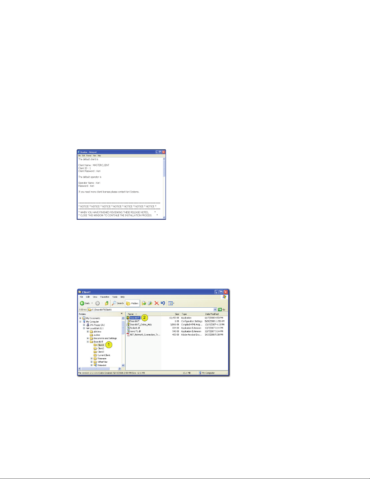
3. Be sure to save the information given in the Notepad program at the end of the installation (see
Figure 1). This information will give you the password and other necessary information to get
DoorsNXT working properly.
Figure 1: DoorsNXT Password
2.2 Setup Client
Once the software has been installed. The first Client must be configured.
NOTE: Licensing for the first Client is included. To use additional clients concurrently, contact Keri
Systems for additional licenses.
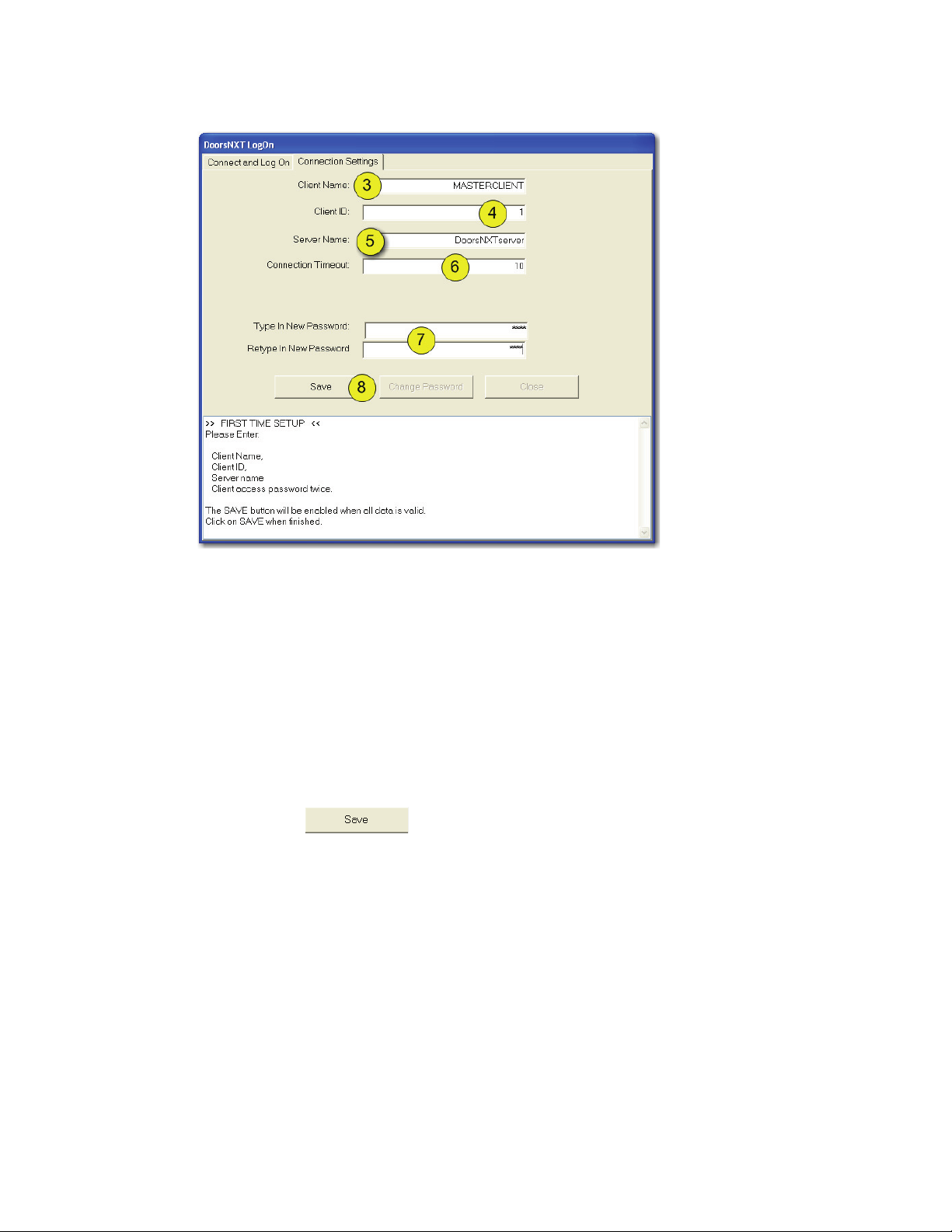
Figure 2: Windows Explorer - Client Application
1. Open up Windows Explorer and locate the DoorsNXT installation. Click on the folder created for
the first Client. The number of Clients available is determined by the selections made in the
software installation process and will vary depending on installation.
2. Double-click on the DoorsNXT application. DoorsNXT will open to the Connection Settings
window (see Figure 3 on page 5).
Page 4 01945-100 Rev. 4.0
Page 7
Keri Systems, Inc. Doors Ne
tXtremeTM Reference Manual
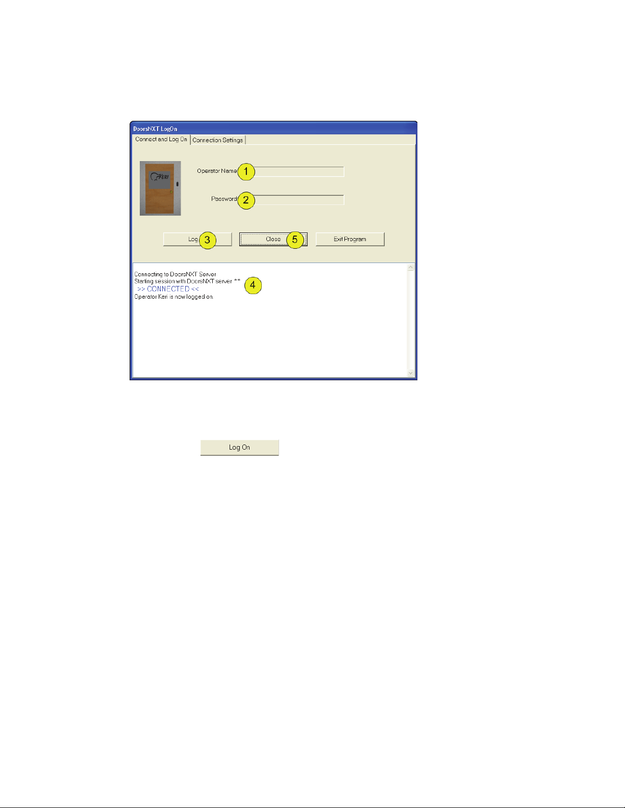
Figure 3: DoorsNXT - Connection Settings
3. In the Client Name field, enter “MASTERCLIENT.”
NOTE:
etc. to help distinguish the clients from each other.
4. In the Client ID field, enter an integer to be assigned
5. In the Server Name field, enter the name of the server.
6. Leave the Connection Timeout field at the default of “10” seconds.
7. Type in the new password in the two fields given. The password was given to you during the
8. Click on the button.
NOTE: Repeat steps 1-7 for each Client.
For multiple clients, you may want to enter “MASTERCLIENT
to the client
and continuing on sequentially with the remaining clients.
installation of DoorsNXT (see Figure 1 on page 4).
,” “CLIENT2,” “CLIENT3,”
. It is recommended to start with 1
01945-100 Rev. 4.0 Page 5
Page 8
Doors NetXtreme
TM
Reference Manual Keri Systems, Inc.
2.3 Log On to DoorsNXT
Click on the Connect and Log On tab.
Figure 4: Log On DoorsNXT
1. Enter the Operator Name as shown on Figure 1 on page 4.
2. Enter the Password as shown on Figure 1 on page 4.
3. Click on the button.
4. If everything has been done correctly, you will receive confirmation that you are logged on to the
server.
5. Click on the “Close” button to close the Log On window.
Page 6 01945-100 Rev. 4.0
Page 9
Keri Systems, Inc. Doors Ne
2.4 Setup System Information Page
Every time the Setup System window is opened, a Setup System Information page window will appear.
This information window states what information is necessary to have on hand prior to begin setup of
the DoorsNXT network (see Figure 5).
tXtremeTM Reference Manual
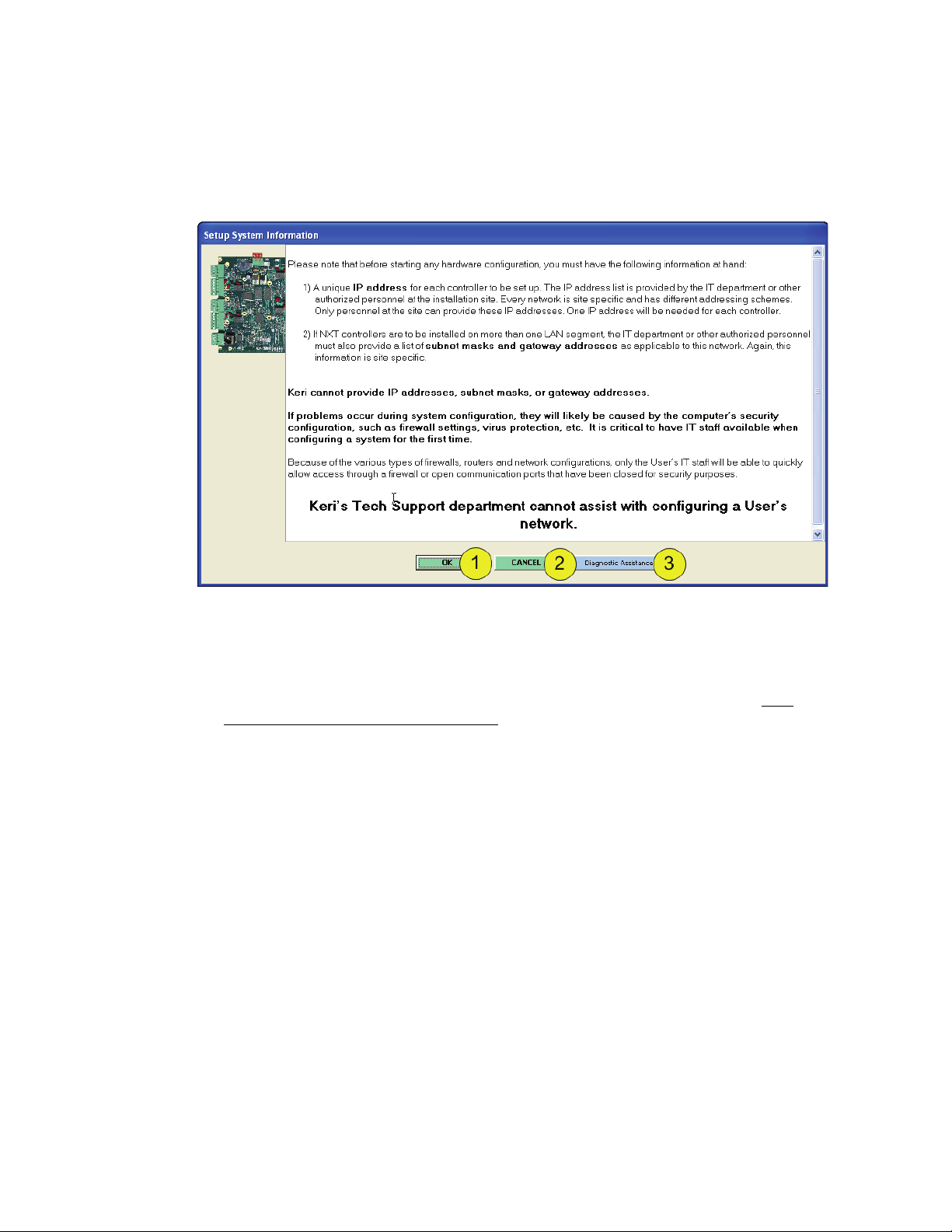
Figure 5: Setup System Information Page
1. Click on the “OK” button to close this window and the Setup System window will appear.
2. Click on the “CANCEL” button to close this window without also opening the Setup System
window.
3. If more information is needed click on the “Diagnostic Assistance” button to open the NXT
Network Connection Troubleshooting Guide (P/N 01508-001). This window will remain open until
either the “OK” or “CANCEL” button is selected.
NOTE: There is no way to stop this window from appearing. Every time the Setup System window is to
be opened, this information window will appear first.
01945-100 Rev. 4.0 Page 7
Page 10
TM
Doors NetXtreme
Reference Manual Keri Systems, Inc.
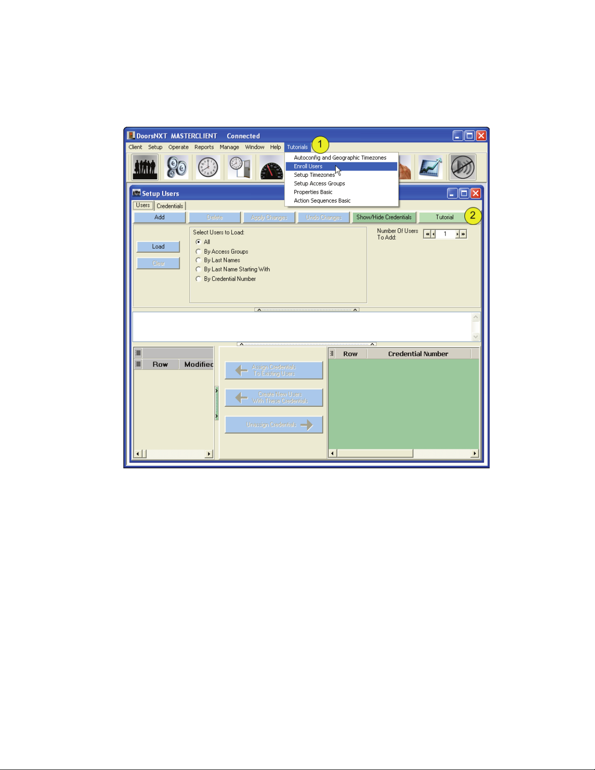
2.5 Tutorials
To assist with basic setup of DoorsNXT, some video tutorials have been created and are available
through the client window.
Figure 6: Tutorials Access
1. All tutorials are available from the Tutorials drop-down menu.
2. If there is a tutorial that applies to a specific window, the “Tutorial” button will be available. Slick
on the button to watch the tutorial available for that particular procedure.
Page 8 01945-100 Rev. 4.0
Page 11
Keri Systems, Inc. Doors NetXtremeTM Reference Manual
3.0 Setup Options and Preferences
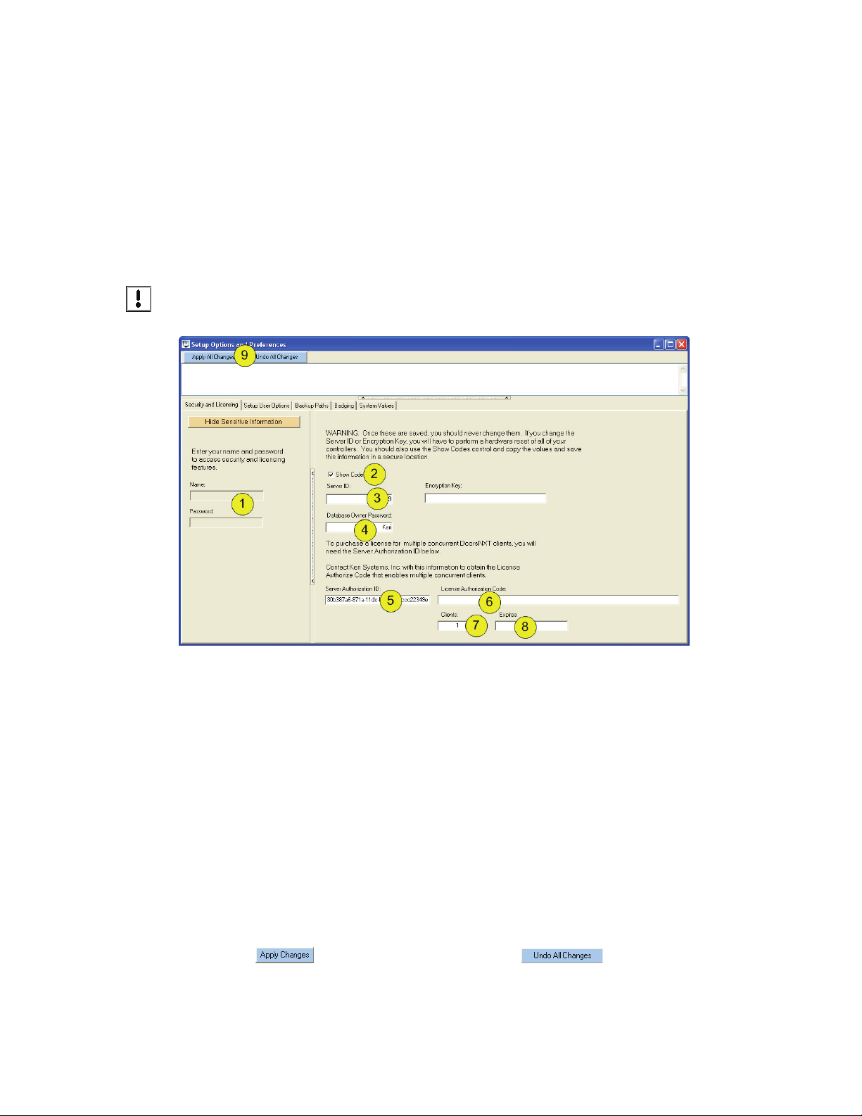
3.1 Setup Security and Licensing
Currently, there are two settings that must be changed upon completion of the installation of DoorsNXT.
• Change the Database Owner Password
• Enter the License Authorization Code (if concurrent cl
Click on Setup > Options and Preferences > Security and Licensing (tab).
ient capabilities are planned)
NOTE: As this
present when entering and viewing security codes.
Figure 7: Setup Security and Client Licensing
1. Enter the Operator Name and Password as shown in “Log On to DoorsNXT” on page 6. When the
correct Operator Name and Password is entered, the side window appears automatically.
2. Click in the Show Codes box.
3. The Server ID is shown. It is recommended that this number be written down and stored in a secure
place for future emergencies.
4. The default Database Owner Password is Keri. Enter a new Owner Password in this field and write
it down along with the Server ID to be stored in a secure place. This password is needed for ALL
DoorsNXT upgrades.
5. If multiple concurrent client capabilities will be needed, contact Keri Systems with the Server
Authorization ID number. Keri Systems will generate an Licensing Authorization Code.
6. Enter the Licensing Authorization Code received from Keri Systems in the field provided. You will
now be able to run multiple clients simultaneously.
7. The Clients field shows how many clients have been licensed. The first client is free and does not
require a License Authorization Code.
8. If there is an expiration date then that date will appear in the “expires” field.
area deals with security issues, it is recommended that only authorized personnel are
9. Click on to save the information, or click on to clear all changes.
use at this time.
NOTE: The Encryption Key is
01945-100 Rev. 4.0 Page 9
not in
Page 12
Doors NetXtreme
TM
Reference Manual Keri Systems, Inc.
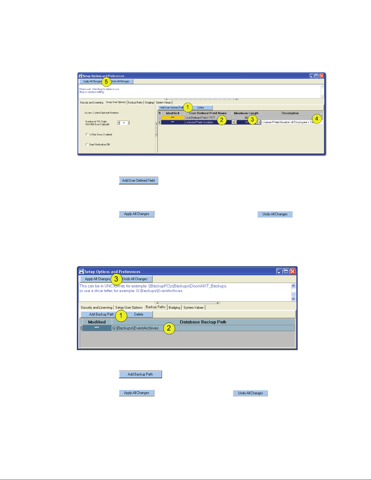
3.2 Setup User Defined Fields
Setup > Options and Preferences > Setup User Options (tab).
Figure 8: Add User Defined Field
1. Click on the button.
2. Enter a nam
3. Enter the maximum number of characters allowed in the field (the range is from 1-256).
4. Enter a description of the purpose of the User Defined Field.
e for the field (to be used in the Setup Users window).
5. Click on the button to save all changes or click on the button to not
save the fields.
3.3 Setup Database Backup Path
Setup > Options and Preferences > Backup Paths (tab).
Figure 9: Setup Database Backup Path
1. Click on the button.
2. Enter the location for the backup file to be used.
3. Click on the to save the path or click on the button to undo the
changes.
Page 10 01945-100 Rev. 4.0
Page 13
Keri Systems, Inc. Doors Ne
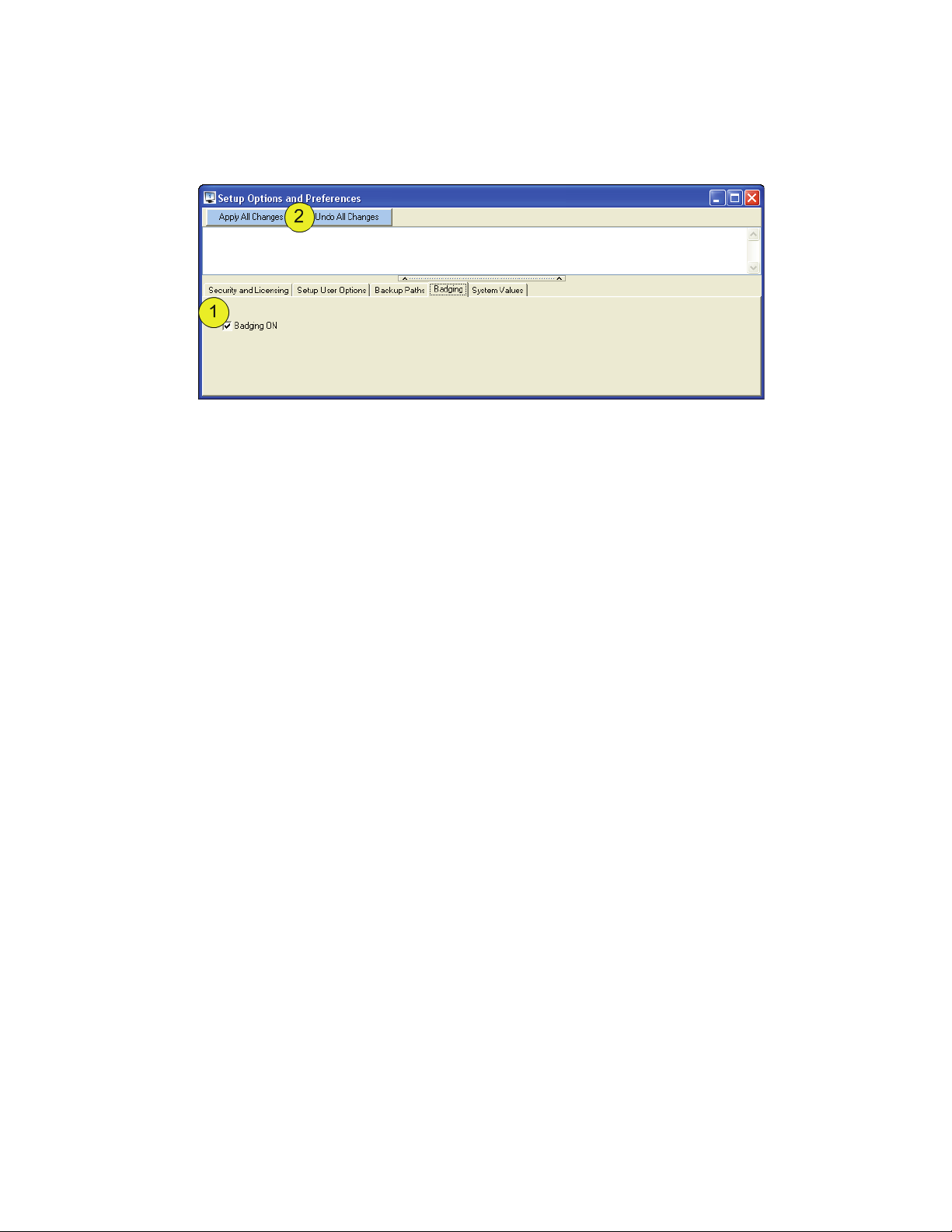
3.4 Badging
Setup > Options and Preferences > Badging (tab).
Figure 10: Enable Badging
Once the badging feature has been enabled, ID Flow by Jolly Technologies may be used to create and
issue badges.
tXtremeTM Reference Manual
01945-100 Rev. 4.0 Page 11
Page 14
Doors NetXtremeTM Reference Manual Keri Systems, Inc.
4.0 Operators
The operators are the people who will be performing the work – creating the databases required by the
rsNXT software to do its job and monitoring the system once everything has been downloaded to
Doo
the controllers.
Since the “Administrator” has access rights to every operation, anyone who knows the name and
password will have complete programming access. Keri Systems recommends keeping this
information a closely guarded secret.
4.1 Create a New Security Level
DoorsNXT comes with 2 pre-programmed security levels. A DoorsNXT Administrator has all access
rights to every operation. Care should be given before assigning Administrator rights to an operator.
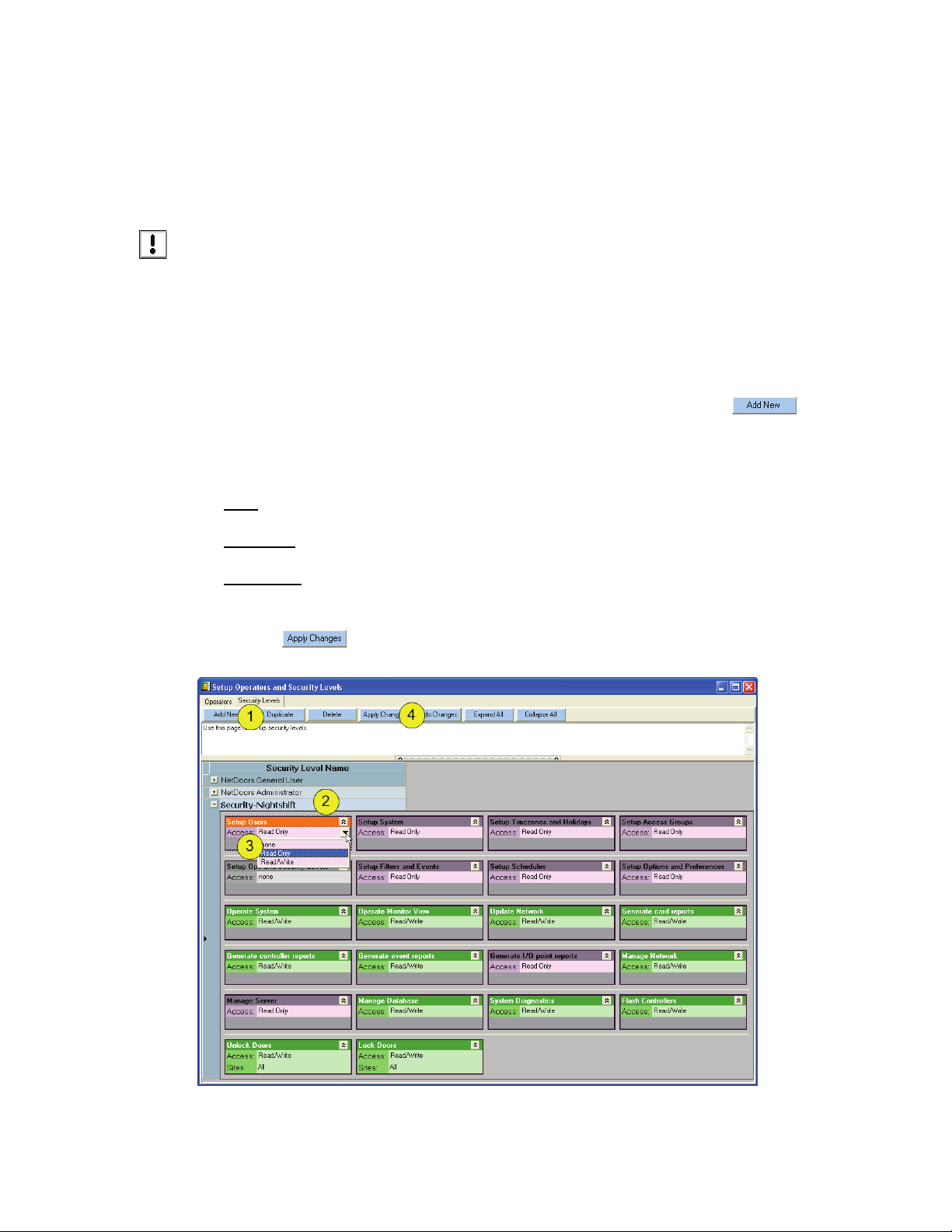
1. In the Setup Operators and Security Levels window/Security Levels tab, click on .
2. Rename the Security Level Name (name is limited to 32 characters in length).
3. Use drop down menu next to “Access:” to choose between none, read only, and read/write for each
security right.
None
The operator does not have operation rights.
Read Only
The operator can view, but not make any changes to this operation.
Read/Write
The operator can view AND change the setup of that operation right.
4. Click on .
Figure 11: Setup Security Level
Page 12 01945-100 Rev. 4.0
Page 15

Keri Systems, Inc. Doors NetXtremeTM Reference Manual
4.1.1 Security Level Rights
The following list are the feature security level rights available for assignment to a security level (which
is then assigned to an operator. Each security level must be created and saved, one-at-a-time. Repeat this
process for each security level.
Setup Users
• Read/Write - allows an operator to perform the Setup Users commands: enrolling credentials,
enrolling users, entering data, voiding, deleting, and assigning access groups.
• Read Only - allows an operator to on
• None - does not allow the operator to view
Setup System
• Read/Write - allows an operator to perform the Setup System commands: entering or editing
the parameters by which a door/controller operates.
• Read Only - allows an operator to review
• None - does not allow the operator to view
Setup Timezones and Holidays
Identifies if an operator is allowed to perform the Setup Timezone commands: creating or editing
Timezones and Holiday schedules or is allowed to have Read Only access to review, but not change,
this information.
ly view user information.
or change user information.
, but not change, the system information.
or change system information.
Setup Access Groups
Identifies if an operator is allowed to perform the Setup Access Group commands: creating or editing
access groups (specifically associating timezones with doors) or is allowed to have Read Only access to
review, but not change, this information.
Setup Operators and Security Levels
Identifies if an operator is allowed to create new operators.
Use Filter Level 1-3
Identifies which levels of view filters are available for the operator to use during monitoring (see “Setup
Monitor View Filters” on page 53).
Setup Filters and Events
Identifies if an operator is allowed to manage the Setup Monitor View Filters settings or is allowed to
have Read Only access to review, but not change this information.
Setup Schedules
Identifies if an operator is allowed to manage the Setup Schedules settings or is allowed to have Read
Only access to review, but not change this information.
Setup Options and Preferences
Identifies if an operator is allowed to manage the Options and Preferences settings or is allowed to have
Read Only access to review, but not change this information.
Operate Monitor View
Identifies if an operator is allowed to modify a Monitor window (a window that views events on the
access control network as they happen) or is allowed to have Read Only access to review, but not
change, this information.
01945-100 Rev. 4.0 Page 13
Page 16

Doors NetXtremeTM Reference Manual Keri Systems, Inc.
Update Network
Identifies if an operator is allowed to update the network or is allowed to have Read Only access to
review, but not change this information.
Create Reports
Identifies if an operator is allowed to generate Event Reports (summaries of events that have occurred
on the access control network).
Report Level 1-3
Identifies which reports an operator is allowed to run (see “Run Pre-Designed Report” on page 59).
Manage Network
Identifies if an operator is allowed to manage network settings or is allowed to have Read Only access
to review, but not change this information.
Manage Server
Identifies if an operator is allowed to manage server settings or is allowed to have Read Only access to
review, but not change this information.
Manage Database
Identifies if an operator is allowed to change the Manage Database window or is allowed to have Read
Only access to review, but not change this information.
System Diagnostics
Identifies if an operator is allowed to manage System Diagnostics settings or is allowed to have Read
Only access to review, but not change this information.
Flash Controllers
Identifies if an operator is allowed to flash (update) controllers on the network or is allowed to have
Read Only access to review, but not change this information.
Operate Hardware
Identifies if an operator is allowed to operate hardware (controllers) or is allowed to have Read Only
access to review, but not change this information.
Page 14 01945-100 Rev. 4.0
Page 17
Keri Systems, Inc. Doors Ne
4.2 Create a New Operator
Setup > Operators and Security Levels > Operators (tab).
NOTE: As this area deals with security issues, it is recommended that only authorized personnel are
present when entering and viewing operator names and passwords.
tXtremeTM Reference Manual
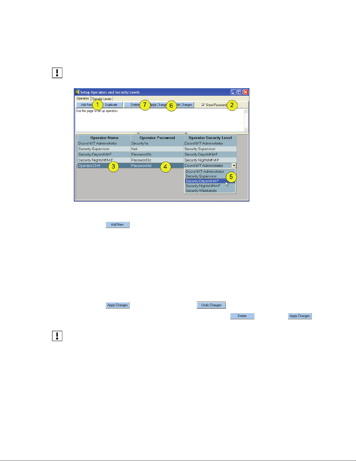
Figure 12: Setup Operators
1. Click on .
2. Click in the “Show Passwords” box.
3. Rename the Operator Name (name is limited to 32 characters in length).
4. Enter a password that the operator can remember.
NOTE: The operator name and password fields are both case sensitive. That is, the program
differentiates between UPPERCASE and lowercase in all three fields. Please keep this in mind when
creating operator names and passwords.
5. Assign a Security Level by using the drop-down menu. Security Levels should have been created in
“Create a New Security Level” on page 12.
6. Click on to save the new operator or to clear it without saving.
7. To delete an Operator, click on the row to be deleted and click , followed by .
NOTE: At this time it is possible to delete settings that are currently in use elsewhere in the software.
cause the program to not function properly. It is recommended that instead of deleting
will
ng this
Doi
any settings, change the name to “UNUSED.” This will be changed
deletions of functions that are in use elsewhere in the software.
in subsequent versions to not allow
01945-100 Rev. 4.0 Page 15
Page 18
TM
Doors NetXtreme
Reference Manual Keri Systems, Inc.
4.3 Setup Geographical Timezones
Click Setup > System > Properties (tab) > Controller (tab).
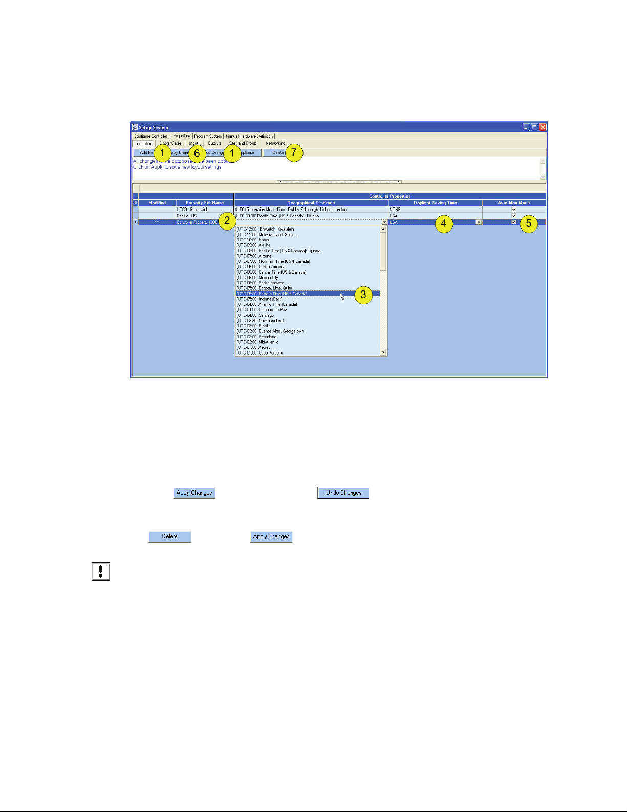
Figure 13: Setup Geographical Timezone
1. Click “Add New” or “Duplicate.”
2. Enter Prop
3. Select from the drop-down menu the Geographical Timezone.
4. Select from the Daylight Saving Time Schedule in place (if any).
5. Select Auto Monitor Mode: “Y” (checked-default) or “N” (unchecked). “Y” means that events will
be automatically collected from controllers.
6. Click to save the timezone or to clear it without saving.
7. To delete a Geographical Timezone Property Set, click on the row to be deleted and click
NOTE: At this time it is possible to delete settings that are currently in use elsewhere in the software.
ng this
Doi
any settings, change the name to “UNUSED.” This will be changed
deletions of functions that are in use elsewhere in the software.
erty Set Name (this is the name that will be used to select this geographical timezone).
, followed by .
will cause the
program to not function properly. It is recommended that instead of deleting
in subsequent versions to not allow
Page 16 01945-100 Rev. 4.0
Page 19
Keri Systems, Inc. Doors NetXtremeTM Reference Manual
5.0 Networking
There are many factors involved in setting up the Network Communication on a DoorsNXT installation.
Some data will need to be provided by a Network Administrator familiar with the network where the
DoorsNXT is to be installed. The main factors to consider when setting up the network are:
• Location of the controllers and Subnet configuration
• Network Security and Firewalls
5.1 Location and Subnet Configuration
DoorsNXT can communicate to controllers on the local subnet or networks outside of the local subnet
using the DoorsNXT Proxy. The Subnet Data (below) will differ for each subnet. Each controller is
configured with a Subnet Property that consists of a Subnet Name, Proxy IP Address, Gateway Address,
and Subnet Mask.
By default DoorsNXT is configured with a single Subnet Property: Local Subnet. This subnet
communicates to the LAN connected to the DoorsNXT Server. There is no Proxy IP Address associated
with the Local Subnet since it is not needed. The Local Subnet property cannot be deleted, but it can be
disabled if necessary.
DoorsNXT can have multiple Subnet properties defined. To modify the local subnet property or create a
new Subnet property, go to Setup Controllers > Properties > Subnets...
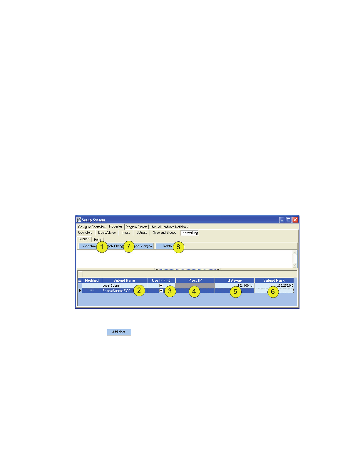
Figure 14: Setup Networking
1. Click on .
2. Rename the Subnet Name, if desired, to something that will make it easy to understand what is
included in that particular Subnet.
3. “Use In Find” allows a subnet to be viewed during autoconfiguration.
4. If there is to be a Proxy IP, enter the address. A Proxy IP is a software agent that performs a
function or operation on behalf of another application. For DoorsNXT, the Proxy IP is a software
service running on a computer attached to a remote subnet.
5. Enter the Gateway IP Address. The Gateway is the IP address of a router used to transport TCP/IP
data packets to network subnets that are outside of the local subnet.
01945-100 Rev. 4.0 Page 17
Page 20
Doors NetXtreme
6. Enter the Subnet Mask IP Address. The Subnet Mask is a method of splitting IP networks into
NOTE: Once a Subnet property is created, controllers located on that Subnet will be assigned the
app
7. Click to save the changes or to clear it without saving.
TM
Reference Manual Keri Systems, Inc.
subgroups. The “mask” separates the portions of the IP address significant to the network from the
bits that are significant to the subnet. The subnet mask has the same format that is used by IP
addresses. An IP address of 192.168.100.1 with a subnet mask of 255.255.255.0 will only be able
to communicate locally to other IP addresses in the range of 192.168.100.1-254. Communications
to IP addresses outside of that subnet will be routed to the gateway.
ro
priate subnet data after an autoconfig is performed.
8. To delet
NOTE: At this time it is possible to delete settings that are currently in use elsewhere in the software.
Doing this
any settings, change the name to “UNUSED.” This will be changed
deletions of functions that are in use elsewhere in the software.
e a Subnet, click on the row to be deleted and click , followed by .
will cause the
program to not function properly. It is recommended that instead of deleting
5.2 Firewall and Network Security
The DoorsNXT server and controllers use specific ports to communicate to each other. These ports must
be allowed access to pass through routers and firewalls in order to allow proper communication. This
includes the software-based firewall applications, such as Windows Firewall, installed on any computer
running DoorsNXT software or services (server, client, and proxy).
in subsequent versions to not allow
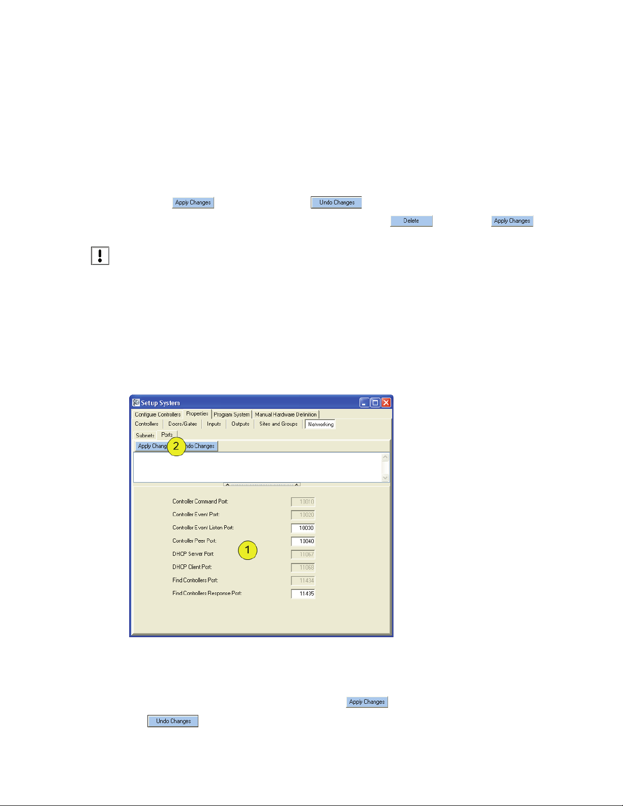
Figure 15: Setup Ports
1. The designated default ports should be left as is, unless instructed to change them by technical
support.
2. If instructed to change the ports, be sure to click to save the new port number, or click
to clear it without saving.
Page 18 01945-100 Rev. 4.0
Page 21

Keri Systems, Inc. Doors Ne
6.0 AutoConfig
Click on Setup > System > Configure Controllers (tab).
Figure 16: Autoconfig - Part One
tXtremeTM Reference Manual
1. Click . The button will change to .Click on it to begin the Autoconfig
process.
2. All available controllers will appear.
3. The Find Status column will show the status of the controller.
4. In the “Take Ownership” column, deselect any controllers you do not want to configure at this time.
5. The IP Assigned column will show if an IP Address has already been assigned to this controller.
6. “Replace With” is used when replacing one controller with another (for further details, see the
“Replacing An NXT Controller” Application Note.)
7. “Keep Current Record” allows previously assigned parameters should be kept when an autoconfig
is performed that changes a portion of the system. “Keep Current Record” allows for certain areas
to be kept “as is” while adding additional hardware.
01945-100 Rev. 4.0 Page 19
Page 22
Doors NetXtreme
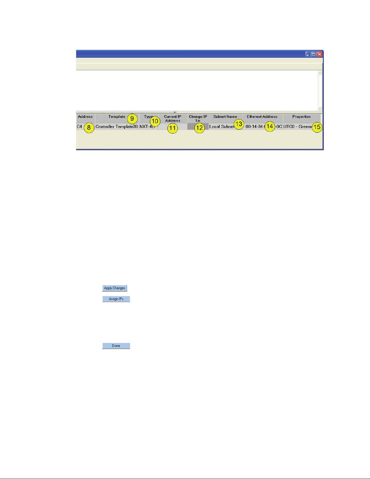
Figure 17: Autoconfig - Part Two
8. The controller’s address is displayed.
9. The Property Te
NOTE: If the Autoconfig detects a change in the configuration, a new template will be created
automatically
to be used, it must be selected. Before changing the Property Template, it is recommended that the
configuration is Verified (see “Verify Controller Configuration” on page 21).
TM
Reference Manual Keri Systems, Inc.
mplate is displayed.
. However, this new template will not
be assigned to the controller. If the new template is
10. The Type of controller (NXT4D, NXT2D) is displayed.
1.
Enter the IP address to be used in the “Current IP Address” field. This is the starting IP address
1
from which the controllers will be assigned individual IP addresses during autoconfiguration.
12. The “Change IP To:” column is used when changing the IP Address of a controller.
13. The Subnet Name being used for the configuration (as set up in “Firewall and Network Security”
on page 18) is displayed. After being assigned during autoconfiguration, it cannot be changed.
14. The Ethernet Address is displayed.
15. The Geographical Timezone currently in use is displayed.
16. Click .
17. Click . (This may take up to 3 minutes as the controllers are assigned IP addresses.)
18. To verify the IP address has been assigned, the IP Assigned column should change from “No” to
“Yes.”
NOTE: If the IP address is outside of the subnet of th
e DoorsNXT server
, autoconfiguration will FAIL.
19. Click .
20. Close the window.
Page 20 01945-100 Rev. 4.0
Page 23
Keri Systems, Inc. Doors Ne
6.1 Verify Controller Configuration
Once the controller has been configured, that configuration can be verified.
Click on Setup > System > Configure Controllers (tab).
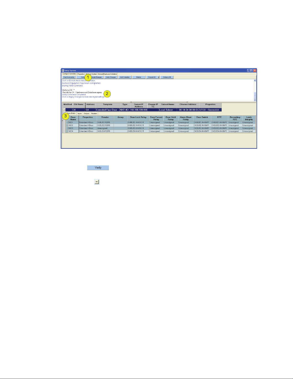
Figure 18: Verify Controllers
tXtremeTM Reference Manual
1. Click on .
2. After completion of the verification process, the results are shown in the message box.
3. Click on the to reveal the configuration of a particular controller.
01945-100 Rev. 4.0 Page 21
Page 24

Doors NetXtremeTM Reference Manual Keri Systems, Inc.
7.0 Setup System Timezones & Holidays
7.1 System Timezones
Click on Setup > Timezones and Holidays > Timezones (tab).
Figure 19: Setup Timezones
There are two predefined timezones: Always and Never
timezone always allows access regardless of time-of-day or day-of-the-week. The Never timezone
never allows access regardless of time-of-day or day-of-the-week.
1. Click .
2. Rename the Timezone to something that will make it easy to understand what is included in that
particular timezone.
3. From the drop-down menu select “Always,” “Never,” or “Use Times” for each day of the week
(and up to 6 holidays).
4. Enter the start time for each day of the week (and up to 6 holidays).
5. Enter the stop time for each day of the week (and up to 6 holidays).
NOTE: Time selections may be made by typing in the time (using a 24-hour clock format), or by rightclicking in the
name
.
NOTE: At this time it is possible to delete settings that are currently in use elsewhere in the software.
ng this
Doi
any settings, change the name to “UNUSED.” This will be changed
deletions of functions that are in use elsewhere in the software.
field and s
Makes a copy of an existing timezone and renames it adding “-copy” to the duplicated
Removes the highlighted timezone.
will cause the
electing “Pick Time” then selecting the desired time from the list.
program to not function properly. It is recommended that instead of deleting
. These timezones are not editable. The Always
in subsequent versions to not allow
Page 22 01945-100 Rev. 4.0
Page 25

Keri Systems, Inc. Doors Ne
tXtremeTM Reference Manual
7.1.1 Graveyard Shift Time Zone Example (Crossing Midnight)
This time zone example is designed for a graveyard shift employee, eligible to work from 11:30 P.M. to
7:30 A.M. Monday/Tuesday through Friday/Saturday.
The graveyard shift time zone is unique in that it starts in one day-of-the-week and ends in the next dayof-the-week. To accommodate this, the time zone uses both the Start1/Stop1 and Start2/Stop2 cells to
cover the split in access times Tuesday through Friday.
• Monday – 11:30 to Tuesday – 07:30 hours (11:30 P.M. to 7:30 A.M.)
• Tuesday – 11:30 to Wednesday – 07:30 hours (11:30 P.M. to 7:30 A.M.)
• Wednesday – 11:30 to Thursday – 07:30 hours (11:30 P.M. to 7:30 A.M.)
• Thursday – 11:30 to Friday – 07:30 hours (11:30 P.M. to 7:30 A.M.)
• Friday – 11:30 to Saturday – 07:30 hours (11:30 P.M. to 7:30 A.M.)
Figure 20: Graveyard Shift Time Zone Example
01945-100 Rev. 4.0 Page 23
Page 26

Doors NetXtreme
TM
Reference Manual Keri Systems, Inc.
8.0 Holidays Tab
Holidays are treated as if they are just another day of the week. This allows holidays to have access time
periods applied to them. Six holiday schedules are available for definition. This allows certain holidays
to have different access times than others do. For example, on holidays such as Presidents’ Day or
Martin Luther King’s birthday government offices are closed but many businesses remain open; on
holidays such as Christmas or Thanksgiving virtually all business and government offices are closed.
An access control network might need to assign holiday access times differently to cover these two
types of holidays.
Before defining holiday schedules, take some time and map out all the holiday possibilities for the site.
Consider the relative importance of the holiday and determine if multiple holiday schedules are
required.
NOTE: Certain holiday dates change from year-to-year (i.e. Easter or Thanksgiving). Operators should
and update the holiday schedules prior to the beginning of a new year to ensure proper holiday
eview
r
coverage.
Figure 21: Setup Holidays
1. Rename “HOLIDAY1” to a name that will make it easy to understand which holidays are included.
2. Click . An empty line appears in the holiday schedule.
3. Use the drop-down calendar to select the date of the holiday. Take care to make sure the correct
month, day, and year have been selected.
4. Designate the holiday as one that reoccurs year after year. This is only for those holidays that take
place on the same date each year (i.e. New Year’s Day, Christmas Day, etc.).
5. Enter the commonly used name of the holiday.
6. Select whether each holiday date should automatically expire at the end of the year.
7. Click to save the holiday schedule or to clear it without saving.
Page 24 01945-100 Rev. 4.0
Page 27

Keri Systems, Inc. Doors NetXtremeTM Reference Manual
9.0 Create and Assign Property Sets
DoorsNXT utilizes p
template that may then be assigned to a number of individual buses, controllers, readers, operators, etc.
roperty sets to allow for common attributes and/or functions to be created into a
9.1 Doors/Gates Property Sets
A property set is a configuration of standard settings that determine the default behavior of the system.
DoorsNXT automatically receives information from the controller that will determine the template
assigned that most closely resembles the wiring of the system. There are four basic templates that may
be assigned. If the wiring of the system does not match one of the four basic templates, a new template
(with a number following) will be generated.
NOTE: Take care not to change this once the
determine what changes may be made to the system and changing the template will make some options
either available or unavailable incorrectly.
Standard 4 Door/Standard 2 Door =
NXT 4x4 module attached.
Extended 4 Door/Extended 2 Door = access control with readers and the NXT 4x4 modules attached
to all Buses.
There may be times when it is necessary to change the template. Care should be taken when doing this.
NOTE: If the Autoconfig detects a change in the configuration, a new template will be created
automatically
to be used, it must be selected. Before changing the Property Template, it is recommended that the
configuration is Verified (see “Verify Controller Configuration” on page 21).
. However, this new template will not
access co
system has detected
ntrol with readers attached to all Buses, without the
be assigned to the controller. If the new template is
the configuration. The template will
Figure 22: Select Template and Timezone
1. Change the controller Name to something that will make it easy to identify throughout the system
and in reports.
2. The basic template of the system may be changed using the drop-down menu available. Care
should be taken before assigning a different template. Only do this when you are sure it is
necessary.
3. Assign the geographical timezone for the physical location of the controller from the drop-down
menu. Only timezones that have been created elsewhere will be available for selection. See “Setup
Geographical Timezones” on page 16.
01945-100 Rev. 4.0 Page 25
Page 28

Doors NetXtremeTM Reference Manual Keri Systems, Inc.
9.1.1 Standard Doors/Gates Properties
Click on Setup > System > Properties (tab) > Doors/Gates.
Each door must be assigned a property set. There are 4 standard property sets that cannot be modified.
However, if these do not fit the necessary requirements, new property sets may be created.
Use the following table to determine whether one of the standard property sets may be used.
Standard 4
Door
Door Type Standard Standard Standard Standard
Auto Unlock/Lock Timezone Never Never Never Never
Unlock Time 10 10 10 10
Extended Unlock Time 20 20 20 20
Open Time 10 10 10 10
Extended Open Time 20 20 20 20
First Person In Not Used Not Used Not Used Not Used
Request To Exit (RTE) 1 Momentary
Unlock
Request To Exit (RTE) 2 Not Used Not Used Not Used Not Used
Door Lock Relay Active Energized Energized Energized Energized
Door Forced Relay Active Not Used Not Used Energized Energized
Door Held Relay Active Not Used Not Used Energized Energized
Alarm Shunt Relay Active Not Used Not Used Energized Energized
Door Switch Contact Type Normally
Closed
Door Switch Circuit Type None (2 State) None (2 State) None (2 State) None (2 State)
Request To Exit 1 Contact
Type
Request To Exit 1 Input
Circuit Type
Request To Exit 2 Contact
Type
Request To Exit 2 Circuit Type None (2 State) None (2 State) None (2 State) None (2 State)
Latch Integrity Contact Type Not Used Not Used Normally
Latch Integrity Circuit Type None (2 State) None (2 State) None (2 State) None (2 State)
Normally
Open
None (2 State) None (2 State) None (2 State) None (2 State)
Not Used Not Used Normally
Standard 2
Door
Momentary
Unlock
Normally
Closed
Normally
Open
Extended 4
Door
Momentary
Unlock
Normally
Open
Normally
Open
Open
Closed
Extended 2
Door
Momentary
Unlock
Normally
Open
Normally
Open
Normally
Open
Normally
Closed
Page 26 01945-100 Rev. 4.0
Page 29

Keri Systems, Inc. Doors Ne
9.1.2 Create a New Doors/Gates Property Set
If one of the standard property sets does not fill the required settings, a new property set will need to be
created.
Figure 23: Door Properties Setup
tXtremeTM Reference Manual
1. Click or highlight an existing property set and click .
When
2.
3. Rename the “Property Set Name” to something that will be easy to understand.
4. Scroll through the list and change the following fields as needed for the specific property set.
Door Type - Door types allow an operator to identify the type of door being used. There are two door
types.
Auto Unlock/Lock Timezone - The unlock/lock time zone allows
a door for the automatic unlocking and locking of that door based on the timezone.
Unlock Time - The door unlock time is the number of seconds the controller holds the door lock relay
in the unlocked position to allow entrance or exit. A timer with this unlock value begins counting once
the card is presented to the reader. When the timer ends or the door closes, whichever occurs first, the
door lock relay resets to the locked position; the default time is 5 seconds (the door lock also resets
when the door is opened if a door status switch is attached to the door and is wired to the controller).
NOTE: The door unlock time is not in addition to the door open time. The door unlock time begins when
a card is presented to the reader and ends when the time specified has expired or the door closes,
whichever occurs first.
Extended Unlock Time - Used in connection with access groups, it allows an extended number of
seconds the controller holds the door lock relay in the unlocked position to allow entrance or exit.
changes have been made to a property set, asterisks appear in the “Modified” column and
will remain there until the changes have been applied to the system.
• Standard – a standard door (default setting)
• Gate – an electric gate (such as a gate controlling a parking lot)
an operator to
assign a time zone to
Open Time - The door open time is the number of seconds a door can be held open for entrance or exit
before the controller generates a door held alarm. The default time is 20 seconds.
NOTE: The door open time is not in addition to the door unlock time. The door open time begins when
or i
the do
01945-100 Rev. 4.0 Page 27
s opened and ends when the time specified has expired.
Page 30

Doors NetXtremeTM Reference Manual Keri Systems, Inc.
Extended Open Time - Used in connection with access groups, it allows certain access groups an
extended number of seconds a door can be held open for entrance or exit before the controller generates
a door held alarm.
First Person In - The First Person In (FPI) function allows an operator to determine if a door should be
automatically unlocked when the unlock/lock time zone begins or if the door should not automatically
unlock until after a person presenting a valid card arrives. This feature is used whenever there is a
concern that employees may be delayed in arriving to a secured site (perhaps due to inclement weather).
Request To Exit (RTE) 1 - The Request to Exit (RTE) input accepts a signal from a normally open
input device such as a push button. There are four door configuration options for RTE 1: Not Used,
Momentary Unlock, Continuous Unlock, and Do Not Unlock.
Exit is not allowed through that door via
• Not Used – There is no request to exit function at all
RTE.
• Momentary Unlock – The request to exit is recorded, the door held open timer
door unlock relay unlocks the door to allow exit.
• Continuous Unlock (CRTE) – (This feature is not supported
recorded and any assigned Auto Unlock/Lock (AUL) time zone is Suspended for a given door.
Then, while the CRTE input is active, the door is unlocked. When CRTE becomes inactive, the
door will assume its AUL time zone configuration state.
• Do Not Unlock – The request to exit is recorded and the door held open timer starts, but the
r mu
doo
or similar device).
st manually be opened for exit (typically the door has a manual door strike, crash bar
.
starts, and the
at this time.) The request to exit is
t su
Request To Exit (RTE) 2 - No
Door Lock Relay Active - Select relay to energize or de-energize if this alarm condition occurs.
Door Forced Relay Active - Select relay to energize or de-energize if this alarm condition occurs.
Door Held Relay Active - Select relay to energize or de-energize if this alarm condition occurs.
Alarm Shunt Relay Active - Select relay to energize or de-energize if this alarm condition occurs.
Door Switch Contact Type - Select normally open or normally closed.
Door Switch Circuit Type - Select the supervised state of the switch.
Request To Exit 1 Contact Type - Select normally open or normally closed.
Request To Exit 1 Input Circuit Type - Select the supervised state of the switch.
Request To Exit 2 Contact Type - Select normally open or normally closed.
Request To Exit 2 Input Circuit Type - Select the supervised state of the switch.
Latch Integrity Contact Type - Not supported at this time.
Latch Integrity Circuit Type - Not supported at this time.
pported at this time.
Page 28 01945-100 Rev. 4.0
Page 31

Keri Systems, Inc. Doors Ne
9.1.3 Configure Input Property Sets
Click on Setup > System > Properties (tab) > Inputs.
Figure 24: Input Property Sets
1. Click “Add New” button or “Duplicate” button.
2. Rename
3. Set Input Mode: Not Used, Normally Open, Normally Closed.
4. Set Supervision: None (2 State), 3 State, 4 State.
5. Set Monitor Timezone: Always, Never, created timezones.
6. Apply Changes or Undo Changes.
the Property set name.
tXtremeTM Reference Manual
9.1.4 Configure Output Property Sets
Click on Setup > System > Properties (tab) > Outputs.
Figure 25: Output Property Sets
1. Click on the “Add New” button or “Duplicate” button.
2. Rename the Property set name.
3. Set Normal Output State: Not Used, Energized, Deenergized.
4. Set Active Time: Supervision: anywhere between Always and 86,400 seconds (1,440 minutes or 24
hours).
5. Set Output Use: General or Elevator.
6. Apply Changes or Undo Changes.
01945-100 Rev. 4.0 Page 29
Page 32

Doors NetXtremeTM Reference Manual Keri Systems, Inc.
9.1.5 Create Sites and Groups
Click on Setup > System > Properties (tab) > Sites and Groups.
9.1.5.1 Create New Site
Figure 26: Sites and Groups Property Set
1. Select the Sites tab.
2. Click on the “Add New” button.
3. Rename the Site Name to something that will make it easy to identify the site throughout the
system and in reports.
4. Click on “Apply Changes” to save the changes or “Undo Changes” to remove the changes made.
9.1.5.2 Create New Group
Figure 27: Sites and Groups Property Set
1. Select the System Groups tab.
2. Click on the “Add New” button.
3. Rename the System Group Name to something that will make it easy to identify the group
throughout the system and in reports.
4. Click on the “Apply Changes” button to save the changes or the “Undo Changes” button to remove
the changes made.
Page 30 01945-100 Rev. 4.0
Page 33

Keri Systems, Inc. Doors NetXtremeTM Reference Manual
9.2 Assign Property Sets to Controllers
Click on Setup > System > Configure Controllers.
9.2.1 Assign Doors/Gates Property Set
Click on Setup > System > Configure Controllers > Doors/Gates (tab).
Figure 28: Configure Controllers
1. Click on the to reveal all doors on the controller.
2. Use the drop-down menu to
3. Each individual aspect of the property set may be changed to match the specifically desired
configuration. Use the scroll-down buttons to select from available options.
4. Check the configuration for all aspects and make changes as appropriate.
5. Click on the “Apply Changes” button to save the configuration, or click on the “Undo Changes”
button to clear all changes made.
NOTE: The option to assign a different site will not appear until a new site has been created. See
“Create New Site” on page 30.
assign a Doors/Gates Property Set to each door.
01945-100 Rev. 4.0 Page 31
Page 34

Doors NetXtreme
TM
Reference Manual Keri Systems, Inc.
9.2.2 Assign Inputs Property Set
Click on Setup > System > Configure Controllers > Inputs (tab).
Figure 29: Assign Inputs Property Set
1. Click on the to reveal all doors on the controller.
2. Verify the Inputs tab has been selected to insure that all inputs in the system are visible.
3. To change the property set of an input, use the drop-down menu and select from the input property
sets designed earlier. Inputs that are in use by the system and unable to be changed are shown in
grey with “In Use By Door” shown.
4. Click on the “Apply Changes” button to save the configuration, or click on the “Undo Changes”
button to clear all changes made.
Page 32 01945-100 Rev. 4.0
Page 35

Keri Systems, Inc. Doors Ne
9.2.3 Assign Outputs Property Set
Click on Setup > System > Configure Controllers > Outputs (tab).
tXtremeTM Reference Manual
Figure 30: Assign Outputs Property Set
1. Click on the to reveal all doors on the controller.
2. Verify the Outputs tab has been selected to insure that all outputs in the system are visible.
3. To change the property set of an output, use the drop-down menu and select from the output
property sets designed earlier. Outputs that are in use by the system and unable to be changed are
shown in grey with “In Use By Door” shown.
4. Click on the “Apply Changes” button to save configuration, or click on the “Undo Changes” to
clear all changes made.
01945-100 Rev. 4.0 Page 33
Page 36

TM
Doors NetXtreme
Reference Manual Keri Systems, Inc.
9.2.4 Assign Reader Type
Click on Setup > System > Configure Controllers > Readers (tab).
Figure 31: Assign Reader Type
1. Click on the to reveal all doors on the controller.
2. Verify
3. The following readers are supported:
the Readers tab has been selected to insure that all readers in the system are visible.
• Keri NXT readers
Rea
• Keri MS readers (with use of a
• Wiegand readers (with use of a Reader Interface Module)
Non 26-bit Wiegand (with use of a Reader Interface Module
•
der Interface Module)
)
Page 34 01945-100 Rev. 4.0
Page 37

Keri Systems, Inc. Doors Ne
9.3 Create New Trigger (I/O) Action Sequence
Setup > System > Program System (tab).
tXtremeTM Reference Manual
Figure 32: Create New Trigger Sequence
1. Click on the to reveal all trigger sources, action sequences, and action sources.
NOTE: If an expected
and verify the expected input has been assig
2. Click on the “Add New Sequence” button.
3. A new section will appear at the
4. Name the action sequence something that will be easily recognizable throughout the system and in
reports.
5. From the list of Trigger Sources (inputs) “drag and drop” the desired source to the Trigger column
in the new sequence.
NOTE: To “drag and drop” a trigger source or action sequence, press and hold down the mouse button
to be placed in the sequence and while continuing to press the mouse button down, move the
he item
on t
mouse until the item is over the box it is to be placed in. Insert the item into the box by releasing the
mouse button (see Figure 33 on page 36).
01945-100 Rev. 4.0 Page 35
trigger source
is not listed, return to “Assign Inputs Property Set” on page 32
ned a property set and the changes have been applied.
bottom of the action sequence listing.
Page 38

Doors NetXtreme
Figure 33: Example of Drag and Drop
TM
Reference Manual Keri Systems, Inc.
6. To use two or more trigger sources, “drag and drop the” ‘and’ or the ‘or
’ to the area between the
trigger sources listed in the sequence.
NOTE:
Once a trigger source (input) has been used, it cannot be used in any other sequence.
7. From the list of Action Sources (outputs) “drag and drop” the desired source to the Actions column
in the new sequence.
8. Click on the “Apply Changes” button to save the action sequence or click on the “Undo Changes”
button to clear all changes made.
Page 36 01945-100 Rev. 4.0
Page 39

Keri Systems, Inc. Doors Ne
10.0 Setup Access Group
Setup > Access Groups.
tXtremeTM Reference Manual
NOTE: If a user has multiple access groups assigned. The one granting the least restrictive acce
will be used.
ss
Figure 34: Setup Access Groups
1. Verify the “Show All” option is selected.
2. Click on the “Add Access Group” button or “Duplicate Access Group” button.
3. Name the Access Group something that will be easily recognizable throughout the system and in
reports.
4. Select the doors that are to be included in the access group.
5. From the drop-down menu, select the timezone to be applied to each door.
6. From the drop-down menu, select any action sequences that should be applied to the particular door
(action sequences must be created in “Create New Trigger (I/O) Action Sequence” on page 35,
before they will appear in the drop-down menu).
7. Apply Changes or Undo Changes.
01945-100 Rev. 4.0 Page 37
Page 40

Doors NetXtremeTM Reference Manual Keri Systems, Inc.
11.0 Credential and User Enrollment
Credentials and Users are enrolled separately. Once they are enrolled, credentials may be assigned to
individual users. More than one credential may be assigned to an individual user.
11.1 Enroll Credentials
11.1.1 Enroll Credentials - Block Enrollment
Click on Setup > Users > Credentials (tab).
Figure 35: Enroll Credentials - Block Enrollment
1. Click on the “Create Credentials” button.
2. Clic
3. From the drop-down menu select the credential format.
4. If Dual Verification has been enabled, the “Type” column will appear. Use the drop-down menu to
5. Enter the digits of the first sequentially numbered credential to be enrolled.
6. Enter the digits of the last sequentially numbered credential to be enrolled.
NOTE: Block enrollment may only be performed using sequentially numbered credentials. If there is
any ga
numbering and enrolled separately.
7. If there is a Facility Code required, enter that number in the field.
8. Click on the “Create Block” button.
9. The credentials are enrolled and visible for verification.
10. Click on the “Apply Changes” button.
Page 38 01945-100 Rev. 4.0
k on the “Start New Set” button.
select whether the credential is to be a primary or secondary credential.
p in the numberin
g, then the credentials should be broken up into groups without any gap in the
Page 41

Keri Systems, Inc. Doors Ne
11.1.2 Enroll Credentials - Learn Mode
To enroll credentials through the “Learn Mode” method means that credentials are presented at the
reader rather than inputting the information by hand.
NOTE: Before beginning the “Learn Mode” process, perform an update on the controller (see “Update
the Network” on page 48).
NOTE: In order to make use of the “Learn Mode” method, DoorsNXT must be connected to the net. To
connect to the net, click on Manage > Network. The box next to “Net” will state whether DoorsNXT is
“connected” or “not connected” to the net. If it is not connected, click on the “Connecting to Net”
button.
tXtremeTM Reference Manual
Figure 36: Enroll Credentials - Learn Mode
1. Click on the “Create Credentials” button.
2. From the drop-down menu, select the reader to be used for presentation of credentials.
3. Click on the “Start Learn Mode” button. If Dual Verification has been enabled and secondary
credentials are to be enrolled, click on the “Start Secondary ID Learn Mode” button.
4. Use the drop-down menu to select the type of Format for the credential.
5. If Dual Verification has been enabled, the “Type” column will appear. Use the drop-down menu to
select whether the credential is to be a primary or secondary credential.
6. Click on the “ + ” to expand the visible information.
7. Present the credentials to the selected reader. As each credential is presented to the reader, it is
listed.
8. Once all credentials have been presented, click on the “Stop Learn Mode” button.
9. Click on the “Apply Changes” button.
NOTE: When using “Learn Mode” to enroll both primary and secondary credentials, the process must
rately for each. Go through all the steps to enroll the primary credentials. Click on the
e sepa
be don
“Apply Changes” button, then go through all the steps to enroll the secondary credentials.
01945-100 Rev. 4.0 Page 39
Page 42

TM
Doors NetXtreme
Reference Manual Keri Systems, Inc.
11.1.3 Enroll Credentials - PIN (Personal Identification Number)
To enroll PINs a keypad must be connected to the controller. When a PIN is used as a secondary
credential, it does not need to be unique. Multiple users may be assigned the same secondary credential.
However, for greater security, unique PINs is recommended.
Figure 37: Enroll PIN
1. Click on the “Create Credentials” button.
2. From
3. Click on the “Start Learn Mode” button. If Dual Verification has been enabled and secondary
4. If Dual Verification has been enabled, the “Type” column will appear. Depending on the button
5. Click on the “ + ” to expand the visible information.
6. Enter each PIN individually. As each credential is presented to the reader, it is listed.
NOTE: The number of PIN digits shown in this window applies only to keypads in 8 bit burst mode. If a
iegan
W
7. Once all PINs have been entered, click
8. Click on the “Apply Changes” button.
NOTE: When using “Learn Mode” to enroll both primary and secondary credentials, the process must
be don
“Apply Changes” button, then go through all the steps to enroll the secondary credentials.
the drop-down menu, select the reader to be used for presentation of credentials. When
enrolling PINs, make sure the reader selected has a keypad.
credentials are to be enrolled, click on the “Start Secondary ID Learn Mode” button.
clicked in step 3, the type of credential (primary or secondary) is automatically entered.
d keypad is in use, PINs are limited to 1 - 65534.
on the “Stop Learn Mode”
e sepa
rately for each. Go through all the steps to enroll the primary credentials. Click on the
button.
Page 40 01945-100 Rev. 4.0
Page 43

Keri Systems, Inc. Doors Ne
11.2 Enroll Users
Click on Setup > Users > Users (tab).
Figure 38: Enroll Users
tXtremeTM Reference Manual
1. Select the number of users to be added.
2. Click on the “Add” button.
3. Enter the first and last name of each user in the fields provided.
4. Select from the drop-down menu the Access Group and Group (if any) to be applied to each user.
Select or de-select each user as “Active” (default has Active selected).
5. This field is for assigning credentials to each user and is explained in “Assign Credentials to Users”
on page 42.
6. Click on the “Apply Changes” button or “Undo Changes” button.
01945-100 Rev. 4.0 Page 41
Page 44

Doors NetXtreme
TM
Reference Manual Keri Systems, Inc.
11.3 Assign Credentials to Users
Click on Setup > Users > Users (tab).
Figure 39: Assign Credentials to Users
1. In the columns on the left of the screen, select the user to be assigned a previously enrolled
credential by clicking on the name so that the entire row is highlighted.
2. In the columns on the right of the screen, select the credential(s) to be assigned to the highlighted
user by clicking on it so that the entire row is highlighted. To assign more than one credential per
user, hold down the control (Ctrl) key while clicking on additional credentials so that multiple lines
are highlighted.
3. In the middle of the screen, click on the “Assign Credentials to Existing Users” button. The
credentials are assigned to the selected user.
4. Click on the “Apply Changes” button or “Undo Changes” button.
Page 42 01945-100 Rev. 4.0
Page 45

Keri Systems, Inc. Doors NetXtremeTM Reference Manual
12.0 IN / OUT Reader
There are three type of In/Out Reader:
• In only
•Out only
•In/Out
12.1 Enable In/Out Reader
Click on Setup > Options and Preferences.
Figure 40: Enable In/Out Reader
1. Select the “Setup User Options” tab.
2. Click in the box next to “In/Out Doors Enabled.”
3. If an 8 Bit Burst keypad is in use, the number of PIN digits to be used may be set as well. (The
range available is from 1-15 digits.)
4. Click on the “Apply All Changes” button.
01945-100 Rev. 4.0 Page 43
Page 46

Doors NetXtreme
TM
Reference Manual Keri Systems, Inc.
12.2 Create In/Out Reader Property Set
Click on Setup > System. Select the Properties tab and click on the Doors/Gates button. A new property
set will need to be created for In/Out Reader.
Figure 41: Create In/Out Reader Property Set
1. Click on the Add New button.
2. Give the property set a name that will make it easy to identify. Using the phrase “in/out reader” in
the set name is recommended.
3. Select the Door Type (standard or gate).
4. From the drop-down menu in the Direction column, select the direction for the reader.
5. Go through the remaining columns to assign the options as desired.
6. Click on the “Apply Changes” button.
Page 44 01945-100 Rev. 4.0
Page 47

Keri Systems, Inc. Doors Ne
12.3 Assign Property Set To In/Out Reader
Click on Setup > System.
Figure 42: Assign Property Set To In/Out Reader
1. Click on the “Configure Controllers” tab.
2. Clic
3. Select the “Doors/Gates” tab.
4. Select the bus that has the In/Out Reader(s) attached.
k on the “+” to expand the controller information.
tXtremeTM Reference Manual
NOTE: It is very important to do the following steps in the order specified. Failure to do so may cause
er col
oth
5. In the Properties column, select the In/Out Reader property set created previously.
6. In the Reader column, use the drop-down menu to select “unassigned” on a different bus (this will
7. The Reader B column appears (if this column is not visible then In/Out Reader has not been
8. Go through the remaining columns to assign the options as desired.
9. Click on the “Apply Changes” button.
umns that need to be set to not appear.
be used as the “out” reader).
enabled). Use the drop-down menu to select the reader that was unassigned in the Reader column.
This will be the “out” reader.
01945-100 Rev. 4.0 Page 45
Page 48

Doors NetXtreme
TM
Reference Manual Keri Systems, Inc.
12.4 Create In/Out Reader Action Sequence
Click on Setup > System.
Figure 43: Create In/Out Reader Action Sequence
1. Click on the “Program System” tab.
2. Clic
3. Click on the “Add New Sequence” button.
4. Give the action sequence a name that will make it easy to identify. Using the direction of the reader
5. From the list of Trigger Sources (inputs) “drag and drop” the trigger source to the Trigger column
6. From the list of Action Sources (outputs) “drag and drop” the desired action to the Actions column
NOTE: Repeat steps 3-6 for every In/Out Reader door.
NOTE: For an example of how to “drag and drop” see Figure 33 on page 36.
7. Click on the “Apply Changes” button.
k on the “+” to expand the controller information.
in the sequence name is recommended.
in the new sequence.
in the new sequence.
Page 46 01945-100 Rev. 4.0
Page 49

Keri Systems, Inc. Doors Ne
12.5 Create In/Out Reader Access Group
Click on Setup > Access Groups.
tXtremeTM Reference Manual
Figure 44: Create In/Out Reader Access Group
1. Click on the “Add Access Group” button.
2. Give the
the sequence name is recommended.
3. Select the door(s) to be used as an In/Out Reader by clicking in the small box.
4. Using the drop-down menu, select the Timezone for the first reader.
5. Using the drop-down menu, select the desired directional Action Sequence (i.e. in).
6. Using the drop-down menu, select the Timezone for the second reader.
7. Using the drop-down menu, select the desired directional Action Sequence (i.e. out).
8. Click on the “Apply Changes” button.
NOTE: See the section “Enroll Users” on page 41 for instructions on assigning access groups to users.
access group a name that will make it easy to identify. Using the direction of the reader in
01945-100 Rev. 4.0 Page 47
Page 50

Doors NetXtreme
TM
Reference Manual Keri Systems, Inc.
13.0 Update the Network
The DoorsNXT software needs to download operating parameters to all controllers on the access control
network.
Click on the button.
Figure 45: Update Window
1. To begin the update, use the drop-down menu to select which controllers should be updated.
NOTE: If a controller has not been assigned an IP address it will
Also, if there is only one controller on the network you may only select the “all” option.
2. Select either the “Complete Update”
NOTE: The “Minimum Update” command uploads from the server to the access control network only
the changes made to
Update” command uploads from the server to the access control network
information.
3. The status of the update will be shown in the window.
the DoorsNXT databases since the last update was performed. The “Complete
or “Minim
um Update” button.
not show in the drop-down menu.
ALL DoorsNXT database
Page 48 01945-100 Rev. 4.0
Page 51

Keri Systems, Inc. Doors Ne
14.0 Collect Events From the Network
Collecting events from all controllers clears the controller buffers and stores the events in an event file
on the hard disk. Event data can then be processed into report formats.
Click on the button.
tXtremeTM Reference Manual
Figure 46: Collect Events Window
1. To collect events, use the drop-down menu to select from which controller(s) events should be
collected.
2. Select the “Collect Events” button.
3. The status of the collection will be shown in the window.
01945-100 Rev. 4.0 Page 49
Page 52

Doors NetXtreme
TM
Reference Manual Keri Systems, Inc.
15.0 Flash Upgrade Controllers/Devices
Click on Manage > Flash Controllers/Devices.
Figure 47: Flash Upgrade Controllers/Devices
1. Click on the “+” to expand the controller information.
2. Click on the “Get Current Version” button.
3. The current versions of all connected hardware will appear.
4. Use the drop-down menu to select from the available upgrades.
5. A check in the box under “Include” means that all connected hardware will be included in the
upgrade. It is recommended to leave it checked. The flash upgrade will automatically skip any
hardware that is already current.
6. Click on the “Start Flash” button.
7. The Flash Status window will show the progress of the upgrade. This may take a few minutes.
Page 50 01945-100 Rev. 4.0
Page 53

Keri Systems, Inc. Doors Ne
tXtremeTM Reference Manual
16.0 Reset Controllers Remotely Through DoorsNXT
A controller reset may be performed through the DoorsNXT software. Go to Setup > Setup Options and
Preferences.
Figure 48: Reset Controllers
1. Enter the Operator Name and Password as shown in “Log
correct Operator Name and Password is entered, the side window appears automatically.
2. Use the drop-down menu to select the controller(s) to be reset remotely.
NOTE: If a controller has not been assigned an IP address it will
Also, if there is only one controller on the network you may only select the “all” option.
3. A basic reset will perform a power cycle on the controller. To perform a basic reset, click on the
“Basic Reset” button.
4. A memory reset will erase all data memory from the controller (leaving IP informtion). To perform
a memory reset, click on the “Memory Reset” button.
5. A factory default restores the controller to how it was received from the factory (with all data and
IP information erased). To reset the controller to the factory default, click on the “Factory Defaults”
button.
On to DoorsNXT” on page 6. When the
not show in the drop-down menu.
01945-100 Rev. 4.0 Page 51
Page 54

Doors NetXtreme
TM
Reference Manual Keri Systems, Inc.
17.0 Operate Hardware
The Operate Hardware commands allow an operator to manually override programmed door controls.
Figure 49: Operate Hardware
1. Select to view the available output points (doors, gates, elevators, and/or general outputs) as icons
or as a list.
2. Select the type of output point to view (doors, gates, elevators, or general outputs).
3. Select the group or site to be viewed.
4. Select the specific individual output points or click on the “Select All” or “Deselect All” buttons.
5. To lock (doors, gates, or elevators) or deactivate (general outputs) click on the “Lock or
Deactivate” button. To unlock (doors, gates, or elevators) or activate (general outputs) click on the
“Unlock or Activate” button.
6. To perform a timed Unlock/Activation, select from the drop-down menu the amount of time for the
unlock/activation (choices are shown in seconds). Once the time has been selected, click on the
“Timed Unlock or Timed Activate” button.
7. All performed events will appear in this window.
Page 52 01945-100 Rev. 4.0
Page 55

Keri Systems, Inc. Doors NetXtremeTM Reference Manual
18.0 Monitor
18.1 Setup Monitor View Filters
Click on Setup > View Filters and Event Messages > View Filters (tab).
Figure 50: View Filters
1. Click “Add New” or “Duplicate.”
2. Rename the view filter. Be sure to choose a name that will make it easy to identify.
3. Select the filter level.
4. Select the poll time (1-60 seconds).
5. Use the Message Type and Message Text columns to determine which messages should be
displayed in the monitor view.
6. Click on the green check mark button to deselect any messages that should NOT be displayed
(default is set for all messages to display).
7. From the drop-down menu, select the site(s) that should be included (default is for all sites to be
included).
8. Click to save the view filter as set up or to clear it without saving.
01945-100 Rev. 4.0 Page 53
Page 56

TM
Doors NetXtreme
Reference Manual Keri Systems, Inc.
18.2 Setup Event Messages
Click on Setup > View Filters and Event Messages > Event Messages (tab).
Figure 51: Event Messages
1. Set the Priority.
2. The Message Te
report and alert viewing easier to understand.
3. Select from the drop-down menu which controllers are to save the event (the default is for all
controllers to save all access, credential, controller, and input/output types of events).
4. Designate by clicking in the empty box (until it turns green with a black check) whether a sound
alert should be generated for each event. Alarm sounds will repeat until acknowledged by the
operator (default is for all sound alerts to be off).
NOTE: The sound alert played is the Windows Exclamation sound, which can be set in the Control
> Soun
Panel
alert acknowledgement is done by clicking on the
5. Click to save the event messages as set up or to clear it without saving.
xt string may be renamed to make it more descriptive to the operator, making
ds window. If the server/client does not have a sound card, the PC’s speaker beeps. Sound
button on the DoorsNXT tool bar.
Page 54 01945-100 Rev. 4.0
Page 57

Keri Systems, Inc. Doors NetXtremeTM Reference Manual
18.3 Show Photo
Use ID Flow by Jolly Technologies to create and issue photos.
18.3.1 Enable Show Photo
Click on Setup > Options and Preferences > Badging (tab).
Figure 52: Enable Show Photo
1. Click on the box next to “Show Photo ON” to enable photos.
2. Clic
k on the “Apply All Changes” button.
18.3.2 Show Photo in Setup Users Window
Click on Setup > Users.
Figure 53: Show Photos in Setup Users
1. Click on the Users tab.
2. Click in the box next to the “Show Photos” field.
3. Click in the box next to the “Load Photos” field.
4. When users are loaded into the Setup Users window, the photo will be displayed.
5. Click on the “Apply Changes” button.
01945-100 Rev. 4.0 Page 55
Page 58

Doors NetXtreme
TM
Reference Manual Keri Systems, Inc.
19.0 System Diagnostics
Manage > System Diagnostics.
Figure 54: System Diagnostics
1. Click on the button.
2. Clic
3. Each individual tab will display more information (see the following sections for more specific
4. Click on the button to receive continuous information. To stop the continuous status,
5. The status line shows the current information on the following topics:
k on the to reveal the information of a particular controller.
information).
click on the button.
•Name
• Number
• Include In Poll
• Online
• Firmware Rev
• Date and Time
• Events
•Credentials
• 12 V Power
• 3 V Power
• Battery Level
• Timezone
•DST
• IP Address
• Ethernet Address
Page 56 01945-100 Rev. 4.0
Page 59

Keri Systems, Inc. D
19.1 System Diagnostics - Modules
Manage > System Diagnostics > Modules (tab).
Figure 55: System Diagnostics - Modules
oors Ne
tXtremeTM Reference Manual
1. The Bus number is shown for each Bus that was detected
2. The Module of each Bus is shown along with the type of reader connected.
3. The Firmware Revision currently installed is displayed.
19.2 System Diagnostics - Inputs
Manage > System Diagnostics > Inputs (tab).
Figure 56: System Diagnostics - Inputs
when Get Status was selected.
1. The Address of each input is displayed.
2. The Bus number where the input is located is displayed.
3. The Circuit Type in use is displayed.
4. The Contact Type in use is displayed.
5. The current state of the input is displayed.
01945-100 Rev. 4.0 Page 57
Page 60

Doors NetXtreme
TM
Reference Manual Keri Systems, Inc.
19.3 System Diagnostics - Relays
Manage > System Diagnostics > Relays (tab).
Figure 57: System Diagnostics - Relays
1. The Address of each relay is displayed.
2. The Bus number where the re
3. The Operation Mode of the relay is displayed.
4. The current state of the relay is displayed.
lay is located is displayed.
19.4 System Diagnostics - Doors
Manage > System Diagnostics > Doors (tab).
Figure 58: System Diagnostics - Doors
For each Door, some basic information is displayed.
Page 58 01945-100 Rev. 4.0
Page 61

Keri Systems, Inc. Doors NetXtremeTM Reference Manual
20.0 Reporting
20.1 Run Pre-Designed Report
Reports > Run.
Figure 59: Run Pre-Designed Report
1. Select the desired report and click on the to reveal any parameters that will need to be specified.
2. Using the drop-down menu, select the “From” and “To” dates and enter them in the appropriate
fields.
3. Using a 24-hour clock to determine the time, enter the “From” and “To” times in the appropriate
fields.
4. These fields may not be edited in the “Run Reports category. To make any changes to these fields,
edit them in the “Create Reports” window (see “Create/Edit Reports” on page 61).
5. To save the date parameters set (perhaps to be used in the future), click on the button to
keep everything as set or click on the button to clear all fields.
6. Once everything has been set up properly, click on the button. The default for predesigned reports is to print to screen.
01945-100 Rev. 4.0 Page 59
Page 62

Doors NetXtreme
Figure 60: Print To Screen
TM
Reference Manual Keri Systems, Inc.
7. The window will show all report information that fits the
criteria selected.
8. If the report contains more than one page, the buttons at the top may be used to go through the
report.
NOTE: Once this window is closed, the report will need to be run again in order to see the information.
a p
rinted copy or a saved file copy is desired, edit the report as described in “Create/Edit Reports” on
If
page 61 to use one of the alternate forms of output.
Page 60 01945-100 Rev. 4.0
Page 63

Keri Systems, Inc. Doors Ne
20.2 Create/Edit Reports
Reports > Create.
tXtremeTM Reference Manual
Figure 61: Create/Edit Reports
1. To create a new report, click on the button or the button to use a predesigned report as the base for a new report.
2. Select the desired report and click on the to display all the parameters.
3. If the report name and description needs to be changed, enter that information in the “Report
Name” and “Report Description” columns.
4. Enter in the “From” and “To” information as desired.
5. Use the available drop-down menus to make any specific selections necessary for the particular
report. If the fields needed do not have a drop down menu, use the “Report Template” drop-down
menu to select a different template to use as a base.
6. Use the drop-down menu to change the report level (if necessary).
7. Use the drop-down menu to select the type of output (choices are “To Screen” or “Select At Run”).
8. If the report can be scheduled to run automatically, make sure there is a green button with a check
mark. To disable this option, click on the button and it will disappear.
9. Click on the button to keep everything as set or click on the button to clear
all fields.
10. Once the report has been created or edited, return to “Run Pre-Designed Report” on page 59 to run
the report.
01945-100 Rev. 4.0 Page 61
Page 64

Doors NetXtremeTM Reference Manual Keri Systems, Inc.
21.0 Dual Verification
The Dual Verification feature, when enab
secure area. The first credential required is called the Primary ID with the second credential called the
Secondary ID. For example, the Primary ID may be an access card with the Secondary ID a Personal
Identification Number (PIN) used in connection with a keypad.
NOTE: For proper setup of the Wiegand Combo Reader, refer to the
Installation Guide (P/N 02501-001).
21.1 Enable Dual Verification
Click on Setup > Options and Preferences.
led, requires one or more credentials to gain access into a
Reader Interface Module
Figure 62: Enable Dual Verification
1. Select the “Setup User Options” tab.
2. Clic
3. To set a limit for the number of PIN entries allowed, click in the box next to “Excessive PIN
4. Set the maximum number of attempts allowed. (The range available is from 1-30.)
5. Set the number of minutes the Primary Credential associated with the failed PIN is to be locked out
6. If an 8 Bit Burst keypad is in use, the number of PIN digits to be used may be set as well. (The
NOTE: If a PIN contains fewer digits than what is required, then a leading zero needs to be added at the
begi
digits and the PIN assigned to a user is “62” then the user needs to enter “00062” or else the entry will
fail. This may also be accomplished by entering “ # ” after the PIN instead of adding the zeros (i.e.
“62#”).
7. Click on the “Apply All Changes” button.
Page 62 01945-100 Rev. 4.0
k in the box next to “Dual Verification ON.” More options for Dual Verification will appear.
Attempts ON.” Additional options for the Excessive PIN attempts will appear.
once the maximum number of attempts has been reached. (The range available is from 1-60
minutes.)
range available is from 1-15 numbers.)
nning for each di
git needed to meet the required number. For example, if the PIN is set up for 5
Page 65

Keri Systems, Inc. Doors Ne
21.2 Create Dual Verification Property Set
Click on Setup > System. Select the Properties tab and click on the Doors/Gates button. A new property
set will need to be created for Dual Verification.
Figure 63:Create Dual Verification Property Set
1. Click on the Add New button.
2. Give the property set a name that will make it easy to identify. Using the phrase “dual verification”
in the set name is recommended.
3. Select the Door Type (standard or gate).
4. Select “YES” from the drop-down menu in the Dual Verification column. Go through the following
columns and set them as desired until reaching the “Dual Verification Required Timezone” column.
5. Dual Verification reader(s) may have separate timezones assigned (for example, if Dual
Verification is only to be used after business hours). In the “Dual Verification Required Timezone”
column, select from the drop-down menu the timezone to be used.
6. In the “Dual Verification Wait Time” column, select from the drop-down menu the length of time
the reader will wait for the secondary credential to be entered before timing out (the range available
is from 1-60 seconds). Continue through the remaining columns to assign the options as desired.
7. Click on the “Apply Changes” button.
tXtremeTM Reference Manual
01945-100 Rev. 4.0 Page 63
Page 66

Doors NetXtreme
TM
Reference Manual Keri Systems, Inc.
21.3 Assign Dual Verification Property Set and Reader(s)
Click on Setup > System.
Figure 64: Assign Dual Verification Property Set and Reader(s)
1. Click on the “Configure Controllers” tab.
2. Clic
3. Select the “Doors/Gates” tab.
4. Select the bus that has the Dual Verification reader(s) attached.
NOTE: It is very important to do the following steps in the order specified. Failure to do so may cause
oth
5. In the Reader column, use the drop-down menu to select “unassigned” for all readers on all busses.
6. In the Properties column, select the Dual Verification property set created previously. Return to the
7. The Secondary Reader column appears (if this column is not visible then Dual Verification has not
8. Click on the “Apply Changes” button.
k on the “+” to expand the controller information.
er col
umns that need to be set to not appear.
Reader column and use the drop-down menu to select the appropriate reader on the controller and
bus to be used for Dual Verification.
been enabled). This column is only to be used when 2 separate readers are to be used for Dual
Verification. One of the readers on another bus must be unassigned using the drop-down menu,
then assign that reader to the bus with Dual Verification. If a combo reader/keypad is in use, then
the Secondary Column must have the same reader assigned as is in the Reader column.
Page 64 01945-100 Rev. 4.0
Page 67

Keri Systems, Inc. Doors Ne
21.4 Create Dual Verification Action Sequence
Click on Setup > System.
tXtremeTM Reference Manual
Figure 65: Create Dual Verification Action Sequence
1. Click on the “Program System” tab.
2. Clic
3. Click on the “Add New Sequence” button.
4. Give the action sequence a name that will make it easy to identify. Using the phrase “Dual
5. From the list of Trigger Sources (inputs) “drag and drop” the Dual Verification source to the
6. From the list of Action Sources (outputs) “drag and drop” the desired action to the Actions column
NOTE: Repeat steps 3-6 for every Dual Verification door.
NOTE: For an example of how to “drag and drop” see Figure 33 on page 36.
7. Click on the “Apply Changes” button.
k on the “+” to expand the controller information.
Verification” in the sequence name is recommended.
Trigger column in the new sequence.
in the new sequence.
01945-100 Rev. 4.0 Page 65
Page 68

Doors NetXtreme
TM
Reference Manual Keri Systems, Inc.
21.5 Create Dual Verification Access Group
Click on Setup > Access Groups.
Figure 66: Create Dual Verification Access Group
1. Click on the “Add Access Group” button.
2. Give the access group a name that will make it easy to identify. Using the phrase “Dual
Verification” in the name is recommended.
3. Select the door(s) to be used with Dual Verification by clicking in the small box.
4. Using the drop-down menu, select the Timezone to be used for this door in this access group.
5. Using the drop-down menu, select the Dual Verification Action Sequence.
6. Click on the “Apply Changes” button.
Page 66 01945-100 Rev. 4.0
Page 69

Keri Systems, Inc. Doors Ne
tXtremeTM Reference Manual
21.5.1 Create Standard Access Group on Dual Verification Door
A door may be used for both Dual Verification and Standard Access. This is done by creating 2 separate
access groups that use the same reader. One group is set up to use Dual Verification (as shown in the
“Create Dual Verification Access Group” section). Another group is set up to use Standard Access.
Whether an individual needs to present two credentials or is exempt from entering a secondary
credential will be determined by the access group assigned to them.
Figure 67: Create Standard Access Group on Dual Verification Door
1. Click on the “Add Access Group” button.
2. Give
3. Select the door(s) to be used by clicking in the small box.
4. Using the drop-down menu, instead of selecting the Dual Verification Action Sequence, select a
5. Click on the “Apply Changes” button.
the access group a name that will make it easy to identify.
Standard Access Action Sequence.
21.6 Update the Network
Once all the previous setup has been performed a network update must be performed before
enrolling credentials and users. If an update is not performed, then all options for enrolling
credentials and users may not be available.
01945-100 Rev. 4.0 Page 67
Page 70

Doors NetXtremeTM Reference Manual Keri Systems, Inc.
21.7 Enroll Primary and Secondary Credentials
Enroll primary and secondary credentials as instructed in “Enroll Credentials” on page 38.
NOTE: Secondary Credentials do not need to be unique. Multiple users may be assigned the same
secondary credent
ial.
21.8 Enroll Users
Enroll users as instructed in “Enroll Users” on page 41.
21.9 Assign Primary and Secondary Credentials To Users
Figure 68: Assign Primary and Secondary Credentials To Users
1. Select All users to display.
2. Click on the “Load” button. All users should will regardless of their assigned access groups, etc.
3. If the credentials are not visible, click on the “Show/Hide Credentials.”
4. Highlight the users to be assigned the secondary credentials by clicking on the row. To select more
than one user, hold down the “Ctrl” key and select each row to be included.
5. Assign the “Dual Verification” access group to the user.
NOTE: Users may be assigned more than one access group.
6. Click on either the “Primary Credentials” or “Secondary Credentials” tab.
7. Highlight the credentials to be used by clicking on the row. To select more than one credential, hold
down the “Ctrl” key and select each row to be included.
8. If the Secondary IDs are not showing, click in the box next “Show Secondary IDs” to show the
secondary IDs.
9. To assign Primary credentials, click on the “Assign Credentials To Existing Users” button. To
assign Secondary credentials, click on the “Assign Secondary Credentials To Existing Users”
button. The credentials are assigned to the selected users.
10. Click on the “Apply Changes” button. Perform an update to send this information to the controller.
Page 68 01945-100 Rev. 4.0
Page 71

Keri Systems, Inc. Doors NetXtremeTM Reference Manual
End of document.
01945-100 Rev. 4.0 Page 69
Page 72

Doors NetXtremeTM Reference Manual Keri Systems, Inc.
Page 70 01945-100 Rev. 4.0
Page 73

Keri Systems, Inc. Doors NetXtreme™ Reference Manual
Index
A
Access Group
Setup, 0-37
B
Backup, 0-10
Badging, 0-11
Block Enrollment, 0-38
C
Client Setup, 0-4
Collect Events, 0-49
Configuration
Controller, 0-19
Location, 0-17
Subnet, 0-17
Controller Configuration
AutoConfig, 0-19
Verify, 0-21
Controller Reset, 0-51
Credentials
Assign To Users, 0-42
Block Enrollment, 0-38
Learn Mode Enrollment, 0-39
PIN Enrollment, 0-40
Crossing Midnight Time Zone Example, 0-23
D
Database Programming
Operators
Editing the Default Operator, 0-12
Doors
System Diagnostics, 0-58
Doors/Gates
Assign Property Set, 0-31
Dual Verification
Assign Property Set and Reader, 0-64
Create Access Group, 0-66
Create Action Sequence, 0-65
Create Property Set, 0-63
Enable, 0-62
Enroll Primary and Secondary Credentials, 0-
68
Standard Access on Dual Verification Door,
0-67
Dual Verification, 0-62
E
Enroll
Block Enrollment, 0-38
Credentials, 0-38
Learn Mode Enrollment, 0-39
PIN 0-40
Users, 0-41
Event Messages, 0-54
F
Firewall, 0-18
Flash Upgrade, 0-50
G
Geographical Timezones, 0-16
Groups
Create Property Set, 0-30
H
Hardware Operation, 0-52
Help
Tutorials, 0-8
I
In/Out Reader
Assign Property Set, 0-45
Create Access Group, 0-47
Create Action Sequence, 0-46
Create Property Set, 0-44
Enable, 0-43
In/Out Reader, 0-43
Inputs
Assign Property Set, 0-32
Configure Property Set, 0-29
System Diagnostics, 0-57
Installation of Software, 0-4
Introduction to DoorsNXT, 0-3
L
Learn Mode Enrollment, 0-39
Licensing and Security Setup, 0-9
Location Configuration, 0-17
Log On to DoorsNXT, 0-6
01945-100 Rev. 4.0 Index Page 1
Page 74

Doors NetXtreme™ Reference Manual Keri Systems, Inc.
M
Modules
System Diagnostics, 0-57
Monitor
Setup View Filters, 0-53
N
Networking, 0-17
O
Operate Hardware, 0-52
Operators
Create New Operator, 0-15
Create New Security Level, 0-12
Security Level Rights, 0-13
Outputs
Assign Property Set, 0-33
Create Property Set, 0-29
P
Personal Identification Number
See PIN 0-40
PIN Enrollment, 0-40
Primary Credentials, 0-68
Property Sets
Assign Doors/Gates, 0-31
Assign Inputs, 0-32
Assign Outputs, 0-33
Assign Reader Type, 0-34
Create New Doors/Gates, 0-27
Doors/Gates Standard, 0-26
Doors/Gates, 0-25
Groups, 0-30
Inputs, 0-29
Outputs, 0-29
Sites, 0-30
R
Reader Type
Assign Property Set, 0-34
Relays
System Diagnostics, 0-58
Reports
Create Reports, 0-61
Edit Pre-Designed Reports, 0-61
Run Pre-Designed Report, 0-59
Reset Controllers, 0-51
S
Schedules - See Holiday Schedules
Secondary Credentials, 0-68
Security
Firewall, 0-18
Level Rights, 0-13
Levels, 0-12
Licensing Setup, 0-9
Network, 0-18
Setup
Access Group, 0-37
Client, 0-4
Geographical Timezones, 0-16
Holidays, 0-24
Security and Licensing, 0-9
System Timezones, 0-22
Setup System Information Page, 0-7
Show Photo, 0-55
Sites
Create Property Set, 0-30
Software Installation, 0-4
Standard Access on Dual Verification Door, 0-67
Subnet Configuration, 0-17
System Diagnostics
Doors, 0-58
Inputs, 0-57
Modules, 0-57
Relays, 0-58
System Diagnostics, 0-56
T
Time Zones
Examples
Crossing Midnight, 0-23
Graveyard Shift, 0-23
Tutorials, 0-8
U
Update Network, 0-48
User Defined Fields, 0-10
Users
Assign Credentials, 0-42
Enrollment, 0-41
V
View Filters (Monitor)
Setup, 0-53
Page 2 Index 01945-100 Rev. 4.0
 Loading...