

Page 1

Doors™ for use with Windows™
Access Control Software
Users Guide v2.1
Page 2

© 1998 Keri Systems, Inc. – ALL RIGHTS RESERVED
Document Number 01821-001, Revision 2.1 – October, 1998
Keri Systems, PXL-250, SB-293, Tiger Controller, and Doors are trademarks of Keri Systems, Inc.
Other product names are trademarks or registered trademarks of their owners.
Keri Systems, Inc. reserves the right to change, without notice, product offerings or specifications.
No part of this publication may be reproduced in any form without written permission from Keri Systems, Inc.
Page 3

Keri Systems, Inc. Doors™ Users Guide
Table of Contents
Table of Contents 3
Introduction to Doors™ 9
The Host Computer 11
System Requirements 11
COMTEST Serial Port Test 12
The Loop-Back Plugs 12
Starting COMTEST In Windows 95 12
Starting COMTEST In Windows 3.11 12
Running COMTEST 12
If the Host Computer Fails COMTEST 14
If the Host Computer Passes COMTEST, but there are Still Problems 14
Setting the Host Computer Date and Time 15
Setting the Date and Time in Windows '95 15
Setting the Date and Time in Windows 3.11 15
Software Installation 17
Upgrade Installation 17
Backing Up in Windows 95 17
Backing Up in Windows 3.11 17
New Installation 17
To Install Doors using Windows 95 17
To Install Doors using Windows 3.11 18
Troubleshooting 19
Low System Resources 19
Verifying System Reso urces in Windows 95 19
Verifying System Reso urces in Windows 3.11 19
Missing DLL Files 19
To Copy the Missing DLL Files in Windows 95 20
To Copy the Missing DLL Files in Windows 3.11 20
Recovering an Original Doors Installation 20
Recovery Using Windows 95 20
Recovery Using Windows 3.11 21
Deleting a Backed Up Doors Installation 21
Deleting Using Wind ows 95 21
Deleting Using Window s 3.1 1 21
Users Guide 23
Users Guide Conventions 24
Windows Conventions 25
On-Line Help 25
01821-001 October 1998
Revision 2.1 Page 3
Page 4

Doors™ Users Guide Keri Systems, Inc.
The Order of Operation 25
Logging On the Doors Program 25
Setup and Verify Network Communicat ion 25
Set Communication Parameters 25
Auto-Config 25
Set Time 26
Perform Smart Update 26
Get Controller Status 26
Begin Database Programming 26
Setup Operators 26
Setup Time Zones 26
Setup Doors 26
Setup Access Groups 26
Setup Cards 26
Setup Monitor Windows 26
Download Information to the Network 27
System Operation 27
Advanced Features 27
Logging On 29
Starting the Doors Program 29
Starting the Program in Windows 95 29
Starting the Program in Windows 3.11 30
System Logon 30
Network Update 31
Introducing the Doors Desktop 33
The Desktop 33
The Tool Bar 34
On-Line Help 34
Exiting a Doors Window 35
Exiting in Windows 95 35
Exiting in Windows 3.11 35
Setup/Verify Network Communication 37
Set Communication Parameters 37
Set the COM Port 37
Set the Communication Speed 38
Set the Modem Parameters 39
Save the Communication Parameters 39
Auto-Config 39
Successful Auto-Config 41
Failed Auto-Config 41
Set Controller Time and Date 42
Network Update – Default Parameters 43
Get Controller Status 45
Get Status For All Controllers 45
Get Status For One Controller 47
Database Programming 49
October 1998 01821-001
Page 4 Revision 2.1
Page 5

Keri Systems, Inc. Doors™ Users Guide
Setup Operators 49
Editing the Default Operator 49
Creating a New Operator 50
Setup Time Zones 53
Day-Shift Time Zone Example 53
Janitorial Shift Time Zone Example 56
Grave Shift Time Zone Example (Crossing Midnight) 57
Holiday Schedules 58
Display/Edit a Time Zone 60
Delete a Time Zone 61
Setup Doors/Controllers 63
Set Controller Dial-Out Parameters 63
Enable Controller Dial-Out 63
Set the Dial-Out Threshold Percentage 64
Disable Controller Dial-Out 64
Assign a Door Name 65
Assign a Door Class 66
Disable/Enable a Reader 67
Set a Door Unlock Time 68
Set a Door Open Time 69
Set an Unlock/Lock Time Zone 70
First Person In 71
Alarm Output 72
Setup Access Groups 75
Create a New Access Group 75
Edit an Existing Access Group 80
Add/Remove a Door from the Access Group 81
Change the Time Zone on an Access Group Door 82
Delete an Access Group 84
Setup Cards 87
Card Enrollment – Dialog Box Method 87
Enroll Tab 87
Block Enrollment by Card Number Range 87
Enrolling by Presenting to a Reader 90
Card Data Tab 91
Entering Card Data for a Cardholder 92
Editing Card Data for a Cardholder 94
Voiding a Card 94
Deleting a Card 96
More Card Data 97
Preferences 98
Personal Setup 99
Personal 101
01821-001 October 1998
Revision 2.1 Page 5
Page 6

Doors™ Users Guide Keri Systems, Inc.
Card Enrollment – Spreadsheet Method 103
Enrolling Cards 103
Entering Card Data for a Cardholder 104
Voiding Cards 107
Deleting Cards 109
Sorting Data 110
Block Copying Data 111
Personal Data Fields 113
Editing Cardholder Data 114
Resizing Columns and Rows 116
To Resize a Column 116
To Resize a Row 116
Printing Cardholder Data from the Spreadsheet (Quick Print) 116
Setup Monitor and Events 117
Enable/Disable Auto-Collection 117
Configure Event Monitoring Windows 118
Naming Event Monitoring Windows 118
Message Text Strings 119
Message Text String Definitions 121
Assigning Events to be Monitored 126
Save to File 128
Controller Reports Events 130
Update the Network 133
System Operation 135
Locking, Unlocking, and Updating Doors 135
Lock Doors 136
Lock All Doors 136
Lock All Doors in a Door Class 136
Lock a Single Door 137
Unlock Doors 138
Unlock All Doors 138
Unlock All Doors in a Door Class 139
Unlock a Single Door 140
Timed Unlock 140
Timed Unlock All Doors 140
Timed Unlock All Doors in a Door Class 141
Timed Unlock a Single Door 142
Update Doors 142
Update All Doors 1 42
Update All Doors in a Door Class 143
Update a Single Door in a Door Class 144
Monitor and Collect Events from the Controllers 147
Verifying Communication Status 147
Starting Monitoring 147
Collecting Events 148
Stopping Monitorin g 148
October 1998 01821-001
Page 6 Revision 2.1
Page 7

Keri Systems, Inc. Doors™ Users Guide
Create Event Reports 149
Quick Search Event Report 149
Clear all Fields 149
Select Doors 150
Select Cardholders 151
Select Events 152
Select Dates 152
Generate Report Output 153
View Report on Screen 153
Print Report 154
Save Report to File 154
Power Search Event Reports 155
Field Type and Field Value 156
Boolean Operators 157
Boolean Links 159
Power Search Example 160
Generate the Report 163
Library Tab 163
Save a Search Expression 164
Get a Search Expression 164
Options Tab 165
Reverse Order of Sort 165
Save Card ID Numbers in the Report File 166
Identify an Unknown Ca rd 167
ID by Reading the Card 167
ID by Entering the Internal Number 168
ID by Entering the Card Number 168
Disconnect from the Access Control Network 169
Window Management 169
Cascading Windows 169
Tiling Windows 170
Tiling Windows Horizontally 170
Arranging Icons 171
Cycling Windows 172
Retrieving the Software Revision and Logged Oper ator 17 2
System Maintenance 175
Secure Storage of Source Disks 175
Periodic Doors Software Backup 175
In Windows 95 175
In Windows 3.11 175
Archiving the Event Logs 176
In Windows 95 176
In Windows 3.11 176
Generating Reports from an Archived Event Log 177
01821-001 October 1998
Revision 2.1 Page 7
Page 8

Doors™ Users Guide Keri Systems, Inc.
Advanced Features 179
Multiple Site Control 179
Enable Sites 179
Enter Site Configuration Information 181
Assign a Site Name 182
Enter the Site Address 182
Site Number 182
Site Personal Identification Number (PIN) 182
Site Phone Number 183
Site Modem Initialization String 183
Site Global Secure Time 184
Site Global Unlock Enable 184
Site Comment 184
Adding a New Site 185
Changes in Database Entry and Program Operation 186
Cardholder Spreadsheet Changes 186
Access Group Changes 187
For a New Access Group 187
Update Site 189
Select a Site 189
Quick Search Reports by Site 190
Power Search Reports by Site 191
I/O Control 193
I/O Configu ration 193
Link Configuration 194
Link Parameters 195
I/O Link Example 197
Manual Output Control 202
Appendix 203
Database File Field Definitions 205
Data Format in Single Site Mode – Using the Cardholder’s Name 206
Data Format in Single Site Mode – Using the Cardholder’s Card Number 207
Data Format in Multiple Site Mode – Using the Cardholder’s Name 208
Data Format in Multiple Site Mode – Using the Cardholder’s Card Number 209
Glossary 211
Index 215
October 1998 01821-001
Page 8 Revision 2.1
Page 9

Keri Systems, Inc. Doors™ Users Guide
Introduction to Doors™
Doors™ for use with Windows™ is a software program that configures and manages an
access control system utilizing Keri Systems' PXL-250 Tiger Controllers or PXL-100 Smart
Entry Controllers.
Doors is a fully functional Windows program, mak i ng ful l use of all popular Windows features
such as resizing and relocating windows, drag-and-drop functions, multiple windows open
simultaneously, background operation, and "real-time" operation. Doors operates under
Windows 3.11, Windows 95, or Windows NT.
Doors provides the operator with a user-friendly interface for defining system parameters,
managing card and transaction files, setting timing functions, and preparing reports. For
operators who are familiar with spreadsheet programs (such as Microsoft Excel™), many
operations can be performed in spreadsheet format, with simple sorting, block, and copy
functions. A wizard provides the operator a step-by-step walk-through procedure for creating
Access Groups (a method for associating access doors with time periods of operation). An
extensive on-line help file places assistance at the operator's fingertips.
A dedicated PC is not needed to run Doors. The PC is only needed for entering and uploading
information to the controllers, downloading information from the controllers, or for real-time
system monitoring. Doors uses a propriatary communications protocol to automatically check
all controllers on the network and configures itself according to the connected hardware,
greatly simplifying the system setup procedure.
Doors is capable of managing a single site via a direct connect line or a modem, and is
capable of managing up to 255 remote sites, each via modem. Remote multiple site
management features automatic dial-up of remote sites, global and site specific card
enrollment, global and site specific event reporting, and configurable automatic downloads of
events from controllers.
The Doors software can handle:
• Up to 32 system operators, each with password protection and configurable privileges.
• Up to 32 time zones, each with 4 start/stop intervals.
• 3 holiday schedules, each with up to 32 definable holiday dates.
• An unlimited number of Access Groups (subject to available hard disk space).
• Up to 6 sortable user definable text fields for individual cardholder information in
addition to last name, card number, access group, and department group fields.
• Up to 255 sites.
• Up to 128 controllers per site.
• Up to 128 doors (one per controller), or up to 256 doors (two per controller) if using
optional Satellite boards with every controller.
• Up to 6,400 cards/cardholders.
01821-001 October 1998
Revision 2.1 Page 9
Page 10

Doors™ Users Guide Keri Systems, Inc.
This page is intentionally left blank.
October 1998 01821-001
Page 10 Revision 2.1
Page 11

Keri Systems, Inc Doors™ Users Guide
The Host Computer
System Requirements
For proper operation of the Doors access control software, the host computer operating the
software must meet the following requirements.
• PC compatible computer using a Pentium-90 or faster microprocessor
• minimum of 16 MB of system RAM
• 520 KB of free, conventional memory
• VGA color monitor with VGA graphics card
• 3.5 inch floppy disk drive
• keyboard
• mouse or other pointing device
• 20 MB of hard disc space
• COM port
(2)
with a 16550 UART to support an external modem or a direct RS-232 serial
connection, or an internal 9600 baud (or faster) modem
• one of the following operating systems:
Windows 3.11
(3)
with MS-DOS 6.2 (or greater)
Windows 95
Windows NT
(1)
NOTES
(1)
The larger the number of cards being enrolled, the larger the system RAM should be to
efficiently handle the card database.
(2)
Since all communication between controllers and the Doors software is done through the
host computer's COM port , Doors cannot work if the host computer's COM port is not
working correctly. Keri Systems cannot be held responsible for host computer COM port or
hardware problems. With the Doors software package, Keri Systems, Inc. provides a simple
COM port test that can verify basic operation of the COM port. Please refer to the COMTEST
Program section below for instructions on operating the program.
(3)
This must be the Windows 3.11 upgrade version and not the older Windows 3.0 or 3.1
versions. There are features and improvements made in the 3.11 revision that the Doors
program needs for proper operation. To determine which revision of Windows is on a host
computer, click on the Help/About pull-down menu in the main program window. A text box
will appear listing a variety of information regarding the host computer, including the revision
of the Windows software. If necessary, contact Microsoft or a computer software vendor for
operating system upgrades.
01821-001 October 1998
Revision 2.1 Page 11
Page 12

Doors™ Users Guide Keri Systems, Inc.
COMTEST Serial Port Test
The Keri Systems, Inc. COMTEST program is a simple program. It is designed to send a
string of characters out the host computer's COM port output and see if they are echoed back
to the host computer's COM port input.
It is not designed to determine if the COM port has more seriou s problems such as conflicts
with other devices on the host computer. For these types of problems, troubleshooting by a
computer technician is required.
The Loop-Back Plugs
To use the COM Test utility program, unplug the connection made from the access control
system to the host computer's COM port. Plug in the correct loop-back plug. The loop-back
plug routes the output signal from the serial port back to the input signal. Two plugs are
provided – one with 9 pins and one with 25 pins. Virtually every serial COM port will use one
of these two plugs.
Starting COMTEST In Windows 95
1. Open the Windows Explorer program.
2. Locate the COMTEST.EXE program. For a default software in stallation, the prog ram can
be found in the "\kerisys\doors\utils" subdirectory.
3. Double-click on the COMTEST.EXE program icon, or click on the COMTEST.EXE icon
and then click on the File ⇒ Run pull-down menu option.
4. Skip to the Running COMTEST
section below.
Starting COMTEST In Windows 3.11
1. Open the FILE MANAGER program.
2. Click on the File ⇒ Run pull-down menu.
3. Click on the
software installation, the program can be found in the "\kerisys\doors\utils" subdirectory.
4. Click on the
Browse
Run
button and locate the COMTEST.EXE program. For a default
button.
Running COMTEST
1. When the program begins, the following screen will appear.
KERI SYSTEMS INC. COMM TEST UTILITY
Plug in the Keri Loopback Test plug before starting the test.
Use icon in upper left to quit the program
Type C to set COM port
Type T to test COM port
PORT: COM2
STATUS: Untested
October 1998 01821-001
Page 12 Revision 2.1
Page 13

Keri Systems, Inc Doors™ Users Guide
2. Press the letter C. The following screen will appear.
KERI SYSTEMS INC. COMM TEST UTILITY
Plug in the Keri Loopback Test plug before starting the test.
Type C to set COM port
Type T to test COM port
Use icon in upper left to quit the program
PORT: COM2
STATUS: Untested
Enter 1 = COM1, 2 = COM2, 3 = COM3, 4 = COM4
3. Press the number corresponding to the COM port the host computer is using for
communication with the access control network (in this example, 2 was pressed).The
following screen will appear.
KERI SYSTEMS INC. COMM TEST UTILITY
Plug in the Keri Loopback Test plug before starting the test.
Type C to set COM port
Type T to test COM port
Use icon in upper left to quit the program
PORT: COM2
STATUS: Untested
4. Press the letter T. The following screen will appear.
KERI SYSTEMS INC. COMM TEST UTILITY
Plug in the Keri Loopback Test plug before starting the test.
Type C to set COM port
Type T to test COM port
Use icon in upper left to quit the program
PORT: COM2
STATUS: Untested
Testing, please wait . . .
01821-001 October 1998
Revision 2.1 Page 13
Page 14

Doors™ Users Guide Keri Systems, Inc.
5. The COM port test takes just a few seconds. When complete, if the COM port has passed
the test it is able to send and receive data. The following screen will appear.
KERI SYSTEMS INC. COMM TEST UTILITY
Plug in the Keri Loopback Test plug before starting the test.
Type C to set COM port
Type T to test COM port
Use icon in upper left to quit the program
PORT: COM2
STATUS: Passed
6. If the COM port has failed the test, the following screen will appear (the error message
will vary depending upon what type of error was detected).
KERI SYSTEMS INC. COMM TEST UTILITY
Plug in the Keri Loopback Test plug before starting the test.
Type C to set COM port
Type T to test COM port
Use icon in upper left to quit the program
PORT: COM2
STATUS: Failed
An error has occurred <type of error>
Press any key to continue
7. To rerun the COMTEST, press any key to return to the beginning of the program.
8. To exit the program, either click on the box in the upper-right corner of the
COMTEST window, or click on the Windows icon in the upper-left corner of the
program window and a pull-down menu will appear. In the menu, click on Close.
9. Remove the loop-back plug from the serial port and reinstall the communication cable.
If the Host Comput er F ails COMTEST
If the host computer failed COMTEST, there is a basic problem in transferring data through
the COM port. A computer technician should examine the computer.
If the Host Computer Passes COMTEST, but there are Still Problems
Some COM port problems are beyond the scope of this COM test program. These types of
problems tend to involve several devices within the computer that are trying to use the same
resources within the computer, each device affecting the others. A computer te chnician should
examine the computer to resolve these kinds of problems.
October 1998 01821-001
Page 14 Revision 2.1
Page 15

Keri Systems, Inc Doors™ Users Guide
Setting the Host Computer Date and Time
To ensure that the date and time assigned to events on the access control system are correct,
the date and time kept by the host computer should be checked for accuracy. Part of the
controller configuration process, later in this manual, will be to set the time and date of the
controllers to match that of the host computer.
Setting the Date and Time in Windows '95
The Windows Help file provides instructions on setting the date and time.
1. Click on the
2. Click on
3. Click on the
search for and highlight the Date/Time help entry.
4. Click on the display button and a list of hyperlinks to the instr uctions for setting the date
and time will appear.
Help
button on the Windows Task Bar. A menu will appear.
Start
and a help topics window will appear.
tab and in the first field type
Index
Setting the Date and Time in Windows 3.11
The Windows Help file provides instructions on setting the date and time.
1. Double-click on the
2. Double-click on the
3. On the Control Panel window’s menu bar click on
4. Click on the
5. Under the "How to . . ." heading, click on
6. A window will appear with instructions for setting the date and time.
Contents
window icon to open the Main window.
Main
Control Panel
menu option and a list of selections will appear.
Date/Time
icon to open the Control Panel.
Help
Change the System Date and Time
. This will automatically
. A pull-down menu will appear.
.
01821-001 October 1998
Revision 2.1 Page 15
Page 16

Doors™ Users Guide Keri Systems, Inc.
This page is intentionally left blank.
October 1998 01821-001
Page 16 Revision 2.1
Page 17

Keri Systems, Inc. Doors™ Users Guide
Software Installation
This section covers upgrading an existing Doors software installation, performing a brandnew installation, troubleshooting some basic installation problems, and deleting an old
software installation. For a brand-new installation, please skip to the New Installation
below.
Upgrade Installation
If you have an original revision of the Doors software and you' re up grad ing to a new revisi on,
you should make a complete copy of the original Doors installation into a backup location for
recovery if there is an issue with the new software installation. You must perform this step
before installing the new revision of Doors as the installation pro cess will overwrite critical
files in the original revision making recovery of the original revision impossible.
Backing Up in Windows 95
1. Open the Windows EXPLORER program.
2. Click on the "kerisys" folder icon (typically c:).
3. Click on File ⇒ New ⇒ Folder, or right-click the mouse, scroll down the displaye d list
of available commands, and click on New ⇒ Folder.
4. Enter a name for the backup folder (such as
5. Locate and click on the "kerisys\Doors" folder and then click on Edit ⇒ Copy.
6. Click on the "backup" folder.
7. Click on Edit ⇒ Paste. All files in the "kerisys\Doors" folder will be copied to the
"kerisys\backup" folder.
8. When the copy process is complete, skip to the New Installation
instructions on the new installation of Doors software.
"backup"
).
section below for
section
Backing Up in Windows 3.11
1. Enter the FILE MANAGER program.
2. Locate and click on the "Doors" directory and then click on FILE ⇒ COPY. A prompt
box will appear asking for a destination path.
3. Click in the text box within the prompt box and type the name of the destination path
(such as
4. Click on the
"kerisys\backup" folder.
5. When the directory copy process is complete, skip to the New Installation
for instructions on the new installation of Doors software.
"c:\kerisys\backup"
button. All files in the "kerisys\Doors" folder will be copied to the
Copy
New Installation
A new installation of the Doors software requires 20 MB of free space on the hard disc drive
for program and database storage.
To Install Doors using Windows 95
1. Insert Disk 1 into the host computer's floppy disk drive.
2. Click on the Windows
3. In the start menu, click on the
4. Click in the "Open:" text box and type
5. Click on the OK button. Program installation now begins.
Start
) into which the backup copy can be saved.
button.
button. A run window appears on screen.
RUN
a:\winstall.exe
.
section below
01821-001 October 1998
Revision 2.1 Page 17
Page 18

Doors™ Users Guide Keri Systems, Inc.
6. A text window appears with the README.TXT file for the Doors software. Please read
the README.TXT file for late-breaking information regarding this revision of Doors
software. When you are finished reading, click on the File ⇒ Exit pull-down menu or
click on the box in the upper-right corner of the window.
7. The installation program will then verify that the host computer has at least 20 MB of
available space before allowing the file copying process to begin.
8. The installation program will request a directory name into which the sof twar e should be
loaded. The Doors program uses "\kerisys\doors" as the default directory path for
installing software. If another directory path is desired, click in this text field and enter
that path now. If this installation is an upgrade to an existing installation and the existing
installation is in a different directory path, enter that directory path now.
9. Click on the OK button.
10. The installation program will request an icon name. The default icon name is Doors. If
desired, enter a more descriptive name at this time (perhaps a name including the
software revision).
11. Click on the OK button.
12. A number of files will be copied to the host computer. When disk 1 is complete, the
installation program will prompt for disk 2. Remove disk 1, insert disk 2, an d click the
OK button.
13. A few more files will be copied to the host computer. When the installation is comple te,
an "Installation Successful" banner will appear. Remove disk 2.
14. Click on the OK button and the Doors software is now ready for use.
To Install Doors using Windows 3.11
1. Insert Disk 1 into the host computer's floppy disk drive.
2. Open the Main window.
3. Open the FILE MANAGER program.
4. Click on the File ⇒ Run pull-down menu.
5. Click in the text box and type a:\winstall.exe.
6. Click on the OK button. Program installation now begins.
7. A text box will appear with the README.TXT file for the Doors software. Please read
the README.TXT file for late-breaking information regarding this revision of Doors
software. When you are finished reading, click on the File ⇒ Exit pull-down menu or
click on the box in the upper-right corner of the window.
8. The installation program will then verify that the host computer has at least 20 MB of
available space before allowing the file copying process to begin.
9. The installation program will request a directory name into which the sof twar e should be
loaded. The Doors program uses "\kerisys\doors" as the default directory path for
installing software. If another directory path is desired, click in this text field and enter
that path now. If this installation is an upgrade to an existing installation and the existing
installation is in a different directory path, enter that directory path now.
10. Click on the OK button.
11. The installation program will request an icon name. The default icon name is Doors. If
desired, enter a more descriptive name at this time (perhaps a name including the
software revision).
12. Click on the OK button.
13. A number of files will be copied to the host computer. When disk 1 is complete, the
installation program will prompt for disk 2. Remove disk 1, insert disk 2, an d click the
OK button.
14. A few more files will be copied to the host computer. When the installation is comple te,
an "Installation Successful" banner will appear. Remove disk 2.
15. Click on the OK button and the Doors software is now ready for use.
October 1998 01821-001
Page 18 Revision 2.1
Page 19

Keri Systems, Inc. Doors™ Users Guide
Troubleshooting
The following section provides information on correcting two basic program installat ion/
operation problems and for recovering an original saved installation.
Low System Resources
Sporadic problems in operating the Doors software can be due to an inadequate amount of the
host computer's resources being available for use by the Doors software. The greater the
number of programs open concurrently, the less the amount of system resources available for
any one program. Doors needs approximately 65% of the computer system's resources free
for proper operation.
Verifying System Resources in Windows 95
1. Click on the
2. Click on Settings ⇒ Control Pane l.
3. When the Control Panel window appears, double-click on the
4. When the System Properties window appears, click on the
5. A list of system performance status values will ap pear; o ne of w hich is the system
resources value.
6. The system resources valu e sh oul d be ab ove 65% to ensure proper oper atio n of t he Doors
program. If it is not, close other unneeded programs to release the system resources they
are using.
7. When you have finished viewing the system performance values, click on the OK button
or click on the box in the upper-right corner of the window.
8. If closing programs does not release enough system resources, close all programs, re-boot
the host computer, and then start the Doors program. This will release all system
resources for reallocation.
button on the Task Bar. A menu of selections will appear.
Start
System
Performance
icon.
tab.
Verifying System Resources in Windows 3.11
1. In the Program Manager window, click on Help ⇒ About.
2. A list of information about this Windows installation will appear. One of the items listed
is the system resources value.
3. The system resources valu e sh oul d be ab ove 65% to ensure proper oper atio n of t he Doors
program. If it is not, close other unneeded programs to release the system resources they
are using.
4. When you have finished viewing the installation information, click on the OK button or
click on the box in the upper-right corner of the window.
5. If closing programs does not release enough system resources, close all programs, re-boot
the host computer, restart Windows, and then start the Doors program. This will release
all system resources for reallocation.
Missing DLL Files
Sporadic problems with the screens and buttons in the Doors software in older Windows 3.11
installations can be due to two files that are required for proper operation of the Doors
software but are missing from the Windows installation. In Windows 95 use WINDOWS
EXPLORER and in Windows 3.11 use FILE MANAGER to verify these two files exist in the
"Windows/System" directory.
CTL3D.DLL
CTL3DV2.DLL
01821-001 October 1998
Revision 2.1 Page 19
Page 20

Doors™ Users Guide Keri Systems, Inc.
If these files do not exist, they may be copied from Disk 1 of the Doors installation disks.
Perform the following steps to copy these files to your Windows/System directory.
To Copy the Missing DLL Files in Windows 95
1. Exit the Doors program.
2. Insert Doors installation disk number 1 into the floppy disk drive.
3. Start the WINDOWS EXPLORER program.
4. Click on the floppy disk drive icon, typically a:\.
5. When its file directory appears, click on the CTL3D.DLL file. This file name should now
be highlighted.
6. Hold do wn the CTRL key and click on the CTL3DV2.DLL file. Both file names should
now be high l ighted.
7. Click on Edit ⇒ Copy, or click on the right mouse button, scroll down the displayed list
of available commands, and click on Copy.
8. Scroll down the list of folders and locate the "windows\system" directory. Click on the
"windows\system" directory.
9. Click on Edit ⇒ Paste, or click on the right mouse button, scroll down the displayed list
of available commands, and click on Paste.
10. Restart the Doors program and the DLLs will be applied to t h e program.
To Copy the Missing DLL Files in Windows 3.11
1. Exit the Doors program.
2. Insert Doors installation disk number 1 into the floppy disk drive.
3. Double-click on the Main window icon and then double-click on the FILE MANAGER
program.
4. Click on the floppy disk drive icon, typically a:\.
5. When its file directory appears, click on the CTL3D.DLL file in the right-side of the
window. This file name should now be highlighted.
6. Hold do wn the CTRL key and click on the CTL3DV2.DLL file. Both file names should
now be high l ighted.
7. Click on File ⇒ Copy, or click on the right mouse button, scroll down the displayed list
of available commands, and click on Copy.
8. Click on the hard disk drive icon, typically c:\.
9. When its file directory appears, scroll down the list of folders in the left-side of the
window and locate the "windows\system" directory. Click on the "windows\system"
directory.
10. Click on File ⇒ Paste, or click on the right mouse button, scroll down the displayed list
of available commands, and click on Paste.
11. Restart the Doors program and the DLLs will be applied to t h e program.
Recovering an Original Doors Installation
At times following an upgrade installation, it can become necessary to restore the original
installation of Doors software. Restoration is simply a matter of copying the original
installation back over the new installation.
October 1998 01821-001
Page 20 Revision 2.1
Page 21

Keri Systems, Inc. Doors™ Users Guide
Recovery Using Windows 95
1. Open the WINDOWS EXPLORER program.
2. Locate and click on the backup folder and then click on EDIT ⇒ COPY.
3. Click on the folder to which the original installation should be restored (t ypically
c:\kerisys\doors).
4. Click on E DIT ⇒ PASTE, or click on the right mouse button, scroll down the displayed
list of available commands, and click on Paste.
5. When the folder copy process is complete, the original revision of Doors software has
been restored and is ready for use.
Recovery Using Windows 3.11
1. Enter the FILE MANAGER program.
2. Locate and click on the backup directory and then click on FILE ⇒ COPY. A prompt
box will appear asking for a destination path.
3. Click in the text box within the prompt box and type the name of the destination path
(typically c:\kerisys\doors) into which the original installation should be restored.
4. Click on the OK button.
5. When the directory copy process is complete, the original revision of Doors soft ware has
been restored and is ready for use.
Deleting a Backed Up Doors Installation
If the new installation has been operating correctly for an extended period of time and if disc
storage space is at a premium, the backed up installation can be deleted.
Be sure the new installation is working to your satisfaction before deleting the backed up
installation. Once deleted, the backed up installation cannot be recovered.
Deleting Using Windows 95
1. Open the WINDOWS EXPLORER program.
2. Locate and click on the backup folder and then click on FILE ⇒ DELETE.
3. A file deletion confirmation window will appear. Click on the Yes button.
4. At some point during the file deletion process a p rompt box will appear asking if
executable files should be deleted. Click on the Yes to All button.
5. When the file deletion progress window disa ppear s, the original installation has been
deleted and disc storage space has been recovered.
Deleting Using Windows 3.11
1. Open the FILE MANAGER program.
2. Locate and click on the backup folder and then click on EDIT ⇒ DELETE.
3. A file deletion confirmation window will appear. Click on the Yes button.
4. When the file deletion progress window disa ppear s, the original installation has been
deleted and disc storage space has been recovered.
01821-001 October 1998
Revision 2.1 Page 21
Page 22

Doors™ Users Guide Keri Systems, Inc.
This page is intentionally left blank.
October 1998 01821-001
Page 22 Revision 2.1
Page 23

Keri Systems, Inc. Doors™ Users Guide
Users Guide
Doors is designed to make the access control system configuration and operation as simple as
possible. This is done by breaking the configuration and operation processes into logical
sections. Each section is responsible for a specific operation; whether it is entering
information regarding how some aspect of the system is to be used or physically performing
some operation.
The Users Guide is written for the novice user, learning how to navigate the Doors software
menus and how to use the commands within the menus. The Users Guide presents the
configuration and operation process in a recommended order of implementation. An operator
can configure the system in almost any order, but the order described in the Users Guide
provides the most sequential and complete path for the first time installer and for a new
installation. Generally speaking, each section of the Users Guide builds upon what has been
completed in the previous section.
To present this information, the Users Guide provides "real-world" examples of a new
installation for a small company in an order that logically builds a complete access control
database. By using real-world examples, this Users Guide will reveal the extensive power and
simplicity of the Doors software.
The scenario for these real-world examples consists of a small building with 4 controllers
controlling 5 doors. Figure 1 provides a floor-plan of this building. Access control will be
provided for three exterior doors and for two interior doors. The people working in this
building have a variety of jobs: manufacturing, stockroom, sales, technical, janitorial,
management, so the time of access and area of access requirements differ depending upon the
personnel.
Older revisions of Doors software and controller firmware do not have all the features
described in this Users Guide. This Users Guide is written to describe the capabilities of the
current Doors software and controller firmware, and might not a ccur at el y reflect th e
capabilities of previous software/firmware revi sions.
01821-001 October 1998
Revision 2.1 Page 23
Page 24

Doors™ Users Guide Keri Systems, Inc.
Back Door
PXL-250
Slave Controller (4)
Host
Computer
Emergency Exit
PXL-250
Master Controller (1)
MANUFACTURING AREA
STOCK
ROOM
Figure 1 - Users Guide Site Layout
Users Guide Conventions
There are certain conventions the Users Guide follows for presenting information and for
indicating when an operator needs to perform an action on the computer.
Folder or directory names are identified in the text as "folder/subfolder."
Locating an item under a pull-down menu is identified as Menu Option ⇒ Sub-Menu Option.
Manufacturing/Stockroom Doors
PXL-250 w/ SB-293
Slave Controller (3)
CUSTOMER AREA
Front/Customer Door
PXL-250
Slave Controller (2)
Program names are identified in all UPPER-CASE.
Information to be typed by an operator is identified in
Boldface
.
If a button is clicked to perform an operation, the button icon is displayed or the button name
is shown in
Boldface
.
October 1998 01821-001
Page 24 Revision 2.1
Page 25

Keri Systems, Inc. Doors™ Users Guide
Operation notes are shown in italics. These are things of which to be aware while using the
Doors software.
Items that require special attention or that can dramatically affect the access control network
are prefaced with a caution sign.
Windows Conventions
Doors is a fully compliant Windows program; providing complete operability in Windows and
allowing its program window to be opened, closed, resized, and multi-tasked as any other
Windows compliant program. Please refer to the help file within the Windows operating
system for information on working in Windows.
On-Line Help
To assist the end user there is a "point-and-tell" on-line help file in the Doors software. Once
in the help file, simply point and click on a menu option, command, or selection and a
description of that item is displayed. To call-up the help file when in the Doors progra m,
Click on the Help/Contents pull-down menu or click on the button on the Doors tool bar
(see the Tool Bar section under Introducing the Desk Top
) to open the help file.
The Order of Operation
This section provides a summary of the major sections in the order that they are presented in
the Users Guide.
Logging On the
Each operator has a unique log on password that allows the Doors program to identify the
operator logging on to the program and to track the actions the operator takes while logged
on.
Setup and Verify Network Communication
The setup and verify network communication section describes the process for configuring
the Doors operating parameters to meet those of the host computer and then verifying that
basic communication is indeed happening between host computer and all the controllers on
the access control network.
Set Communication Parameters
Four tasks are performed to set the Doors communication parameters.
1. Set the program’s COM port to match the host computer.
2. Set the program’s communication speed.
3. Set the remote phone number (for remote access via modem).
4. Restart the program to configure Doors with the communication parameters.
Doors
Program
Auto-Config
The Doors program polls the access control network and receives information identifying
which controllers are communicating on the network. It then inserts this information into the
appropriate databases within the Doors program.
01821-001 October 1998
Revision 2.1 Page 25
Page 26

Doors™ Users Guide Keri Systems, Inc.
Set Time
The Doors program then needs to synchronize the time/date between the host computer and
all controllers so that all event can be tracked correctly.
Perform Smart Update
The Doors program downloads default operating information to the access control network.
Get Controller Status
The Doors program polls the access control network and receives information regarding
controller/door configuration. It then inserts this information into the appropriate databases
within the Doors program. This is the quickest way to verify that all controllers/doors are
recognized by the access control system.
Begin Database Programming
Database programming is where the day-to-day operating parameters for the access control
system are entered.
Setup Operators
The setup operators commands allow for the creation of system operators and the assignment
of operator privileges. It is the operators that will be performing the work: creating the
databases r equired by the Doors software to do its job and monitoring the access control
network once everything has been downloaded to the network.
Setup Time Zones
The setup time zones commands allow an op erator to create the various daily time periods and
holiday time periods to be applied to access groups, the auto unlock/lock door function, and
for input/output operations.
Setup Doors
The setup doors commands allow an operator to define the configuration and operation
parameters for all the controllers/doors on the access control network.
Setup Access Groups
The setup access groups commands allow an operator to combine time zones and doors into a
superset of information that is applied to cardholders. In conjunction with time zones, access
groups allow an operator to define which doors an employee is allowed to use at what times.
Setup Cards
The setup cards commands allow an operator to enroll cards into the system and enter
cardholder information, and to void cards from the system. Each cardholder has a card that
identifies that individual to the access control network. When a cardholder pres ents a card to a
reader requesting access, information associated with the card is compared to information in
the databases stored at the controller to determine if that cardholder should be allowed access
through that door.
Setup Monitor Windows
The setup monitor window commands allow an operator to configure up to three different
monitoring windows to allow filtered, real-time tracking of events on the access control
network.
October 1998 01821-001
Page 26 Revision 2.1
Page 27

Keri Systems, Inc. Doors™ Users Guide
Download Information to the Network
The download information to the network command allows an operator to download
information from the program database to the access control network. This information is
used by the controllers in the network to run the access control system.
System Operation
The system operation commands allow an oper ator to manually, immediately perform specific
functions such as:
• unlock and lock doors
• monitor and collect events from controllers
• override regularly programmed door controls
• create and view event reports
Advanced Features
The Doors program is capable of several advanced features that expand the program’s
capabilities. These features include:
• Remote communication with one or more access control networks via modems.
• I/O control – the linking of input events to drive output responses (i.e. an input connected
to a vibration sensor on a window that is linked to an alarm output so that a broken
window will sound an alarm).
01821-001 October 1998
Revision 2.1 Page 27
Page 28

Doors™ Users Guide Keri Systems, Inc.
This page is intentionally left blank.
October 1998 01821-001
Page 28 Revision 2.1
Page 29

Keri Systems, Inc. Doors™ Users Guide
Logging On
The first step is to start the Doors program and log onto the system. In normal operation, the
log on process identifies to the software which operator is entering the program. With this
identification, the program is able to limit the operator’s actions to those that operator has
been approved to perform.
Starting the Doors Program
For both Windows 95 and Windows 3.11, there are several ways to start the Doors program.
The easiest, most common methods are described below.
Starting the Program in
1. From the Windows 95 Task Bar.
• Click on the
• Click on the
• Click on the
• Click on the
• The program now begins.
2. Using WINDOWS EXPLORER.
• Run the WINDOWS EXPLORER program.
• Locate the DOORS.EXE program (it is typically found under the "\kerisys\doors"
folder.
• Either double-click on the DOORS.EXE program icon or click on the File ⇒ Open
pull-down menu.
• The program now begins.
3. Using WINDOWS EXPLORER to create a Windows desk top shortcut.
• Run the WINDOWS EXPLORER program.
• Locate the DOORS.EXE program (it is typically found under the "\kerisys\doors"
folder.
• Click on the DOORS.EXE program icon. It should now be highlighted.
• Either click on the File ⇒ Create Shortcut menu option or right-click on the
DOORS.EXE program icon, scroll down the list of menu options, and select the
Create Shortcut option.
• A new file is created titled "Shortcut to Doors.exe".
• Click on the "Shortcut to Doors.exe" icon and then click on either File ⇒ Copy or
right-click on the "Shortcut to Doors.exe" icon, scroll down the list of menu options,
and select the
• Close the WINDOWS EXPLORER program and click on the main Windows desk
top.
• Right-click the mouse, scroll down the list of menu options, and select th e
option. The new icon for the Doors program will be placed on the desk top.
• This icon will now appear on the desk top every time the Windows program is
entered. Simply double-click on the icon to start the Doors program.
Windows
Start
Programs
Kerisys
Doors
95
button. A pop-up menu of commands appears.
menu option. A pop-up menu of program folders appears.
program folder. A pop-up menu of programs appears.
program icon.
option.
Copy
Paste
01821-001 October 1998
Revision 2.1 Page 29
Page 30
Doors™ Users Guide Keri Systems, Inc.
Starting the Program in Windows 3.11
1. Run the program from the Doors program group.
• Locate the Doors program group on the main window.
• Double-click on the Doors program group icon. A window will open with icons for
all the programs within the Doors program group.
• Locate the DOORS.EXE program icon.
• Double-click on the DOORS.EXE program icon.
• The program now begins.
2. Using FILE MANAGER.
• Run the FILE MANAGER program.
• Locate the DOORS.EXE program (it is typically found under the "\kerisys\doors"
subdirectory.
• Either double-click on the D OORS .EXE pro gram lis t ing o r cl ick on th e Fi l e ⇒ Op e n
pull-down menu.
• The program now begins.
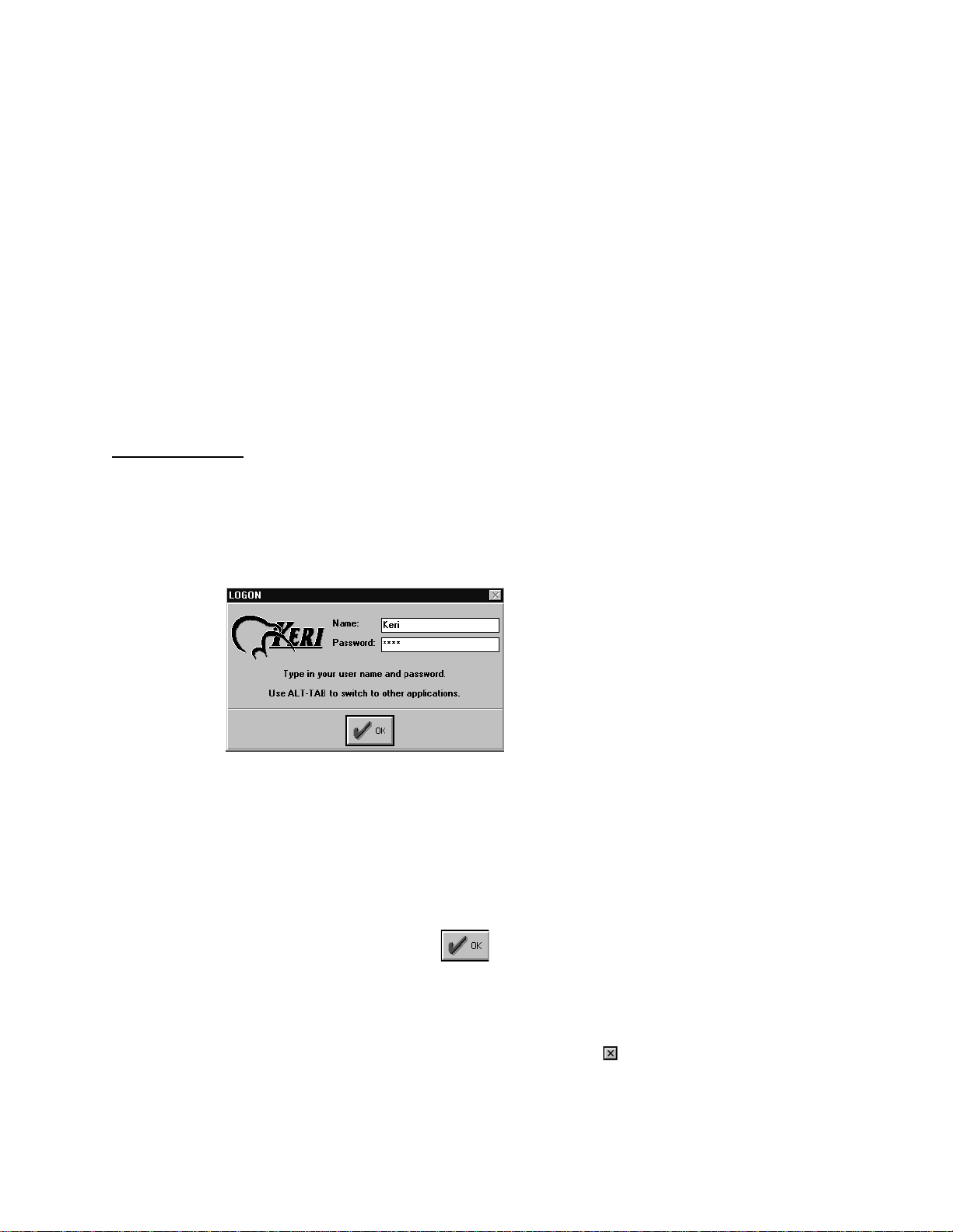
System Logon
Once the program begins, it will prompt for an operator Logon (see Figure 2). This is an
identifying name and password for the operator entering the program. The first time the
program is entered, the default Logon information must be used. Until changed, the default
password provides access to everything in the Doors program. Later in the Doors
configuration process, each authorized operator is assigned identifying names and passwords.
Figure 2 – Logon Screen
To logon the program:
1. Click in the Name box, type
2. Click in t he Password Box, type
of letters so that someone looking over your shoulder during Logon cannot steal your
password.
3. Press
The program will now verify the user name and password. If both are correct, the Logon
window disappears allowing access to the Doors program. If either are incorrect, the user
name and password fields are cleared and the Logon window remains. To leave the Logon
process and return to Windows, for Windows 95 click on the box in the upper-right corner
of the Logon window, for Windows 3.11 click on the File ⇒ Exit pull-down menu optio n.
October 1998 01821-001
Page 30 Revision 2.1
ENTER
or click on the button.
Keri
and press
Keri
ENTER
. Asterisks will appear in the password box instead
.
Page 31

Keri Systems, Inc. Doors™ Users Guide
NOTE: The operator name and password are both case sensitive. That is, the program
differentiates between UPPER CASE and lower case in both the operator name and
password. Please keep this in mind when creating operator names and passwords for your
operators, and when entering your operator name and password to log onto the program.
Network Update
The first time the program is started a "Network Update" window appears (see Figure 3). The
Network Update window indicates first-time communication between the Doors program and
the access control network has not yet been made.
Figure 3 – Network Update Screen
In the future, whenever starting the program, this window appears if a change has been made
to any Doors database that has not yet been sent out to the access control network. This
window serves as a reminder that changes in the database are not physically implemented in
the access control network until they have been uploaded to the network
Click on the OK button to enter the Doors desk top.
01821-001 October 1998
Revision 2.1 Page 31
Page 32

Doors™ Users Guide Keri Systems, Inc.
This page is intentionally left blank.
October 1998 01821-001
Page 32 Revision 2.1
Page 33

Keri Systems, Inc. Doors™ Users Guide
Introducing the Doors Desktop
Every task in Doors is begun from the desktop. Navigating the desktop is simply a matter of
using the mouse to point and click on items, and entering appropriate information when
needed.
The Desktop
There are eight fields on the Doors desktop (see Figure 4).
Figure 4 – The Doors Desktop
1. Window Title Bar – On the left side of the title bar is the name of the program operating
the window; on the right side are the Windows control box es for minimizing or
maximizing the window and for immediately closing the program (refer to Windows’ online help for detailed information on using these boxes) .
2. Menu Bar – A list of the pull-down menus in the Doors program is displayed on the
menu bar. The menu bar is used for accessing all programming and configuration tasks.
Future chapters in this manual provide all the details for using all the commands in the
menu bar. Each pull-down menu option has an underlined letter. To quickly access a
menu option, press the ALT key followed by the underlined letter. Sub-menus also have
underlined letters and can be accessed in a similar manner. For example, to access the
Setup ⇒ System pull-down menu option press
3. Tool Bar – The tool bar is a collection of tool buttons for the most used functions in the
Doors program. Clicking on a tool button immediately opens a function’s window. A
summary of what functions are available on the tool bar appears in the Tool Bar
below.
4. Task Field – When a task is begun by a selection from the menu bar or the tool bar, a
window will appear within this field to manage whatever is necessary to perform this
task. Multiple task windows can be open simultaneously within the task field. Each
window in the task field will have its own title bar identifying the window. The title bar
of the active task in the task field is highlighted.
ALT S S
).
section
01821-001 October 1998
Revision 2.1 Page 33
Page 34

Doors™ Users Guide Keri Systems, Inc.
5. Status/Help Box – The status/help box provides a short description of the active task in
the task field.
6. Monitor Indicator Box – The monitor indicator box displays if a system monitor is
enabled, meaning real-time data collection is being done by the Doors program of events
from the access control network.
7. Date Box – The date box displays the date kept by the host computer.
8. Time Box – The time box displays the time kept by the host computer.
The Tool Bar
The tool bar is a collection of tool buttons for the most used functions in the Doors program
(see Figure 5). Clicking on a tool button immediately opens a function’s window. Placing the
mouse cursor on top of a tool button displays the name of that button beside the mouse cursor.
Figure 5 – The Tool Bar
On-Line Help
On-line help is built into the Doors program. To access on-line help, click on the on the
tool bar or click on Help ⇒ Contents. A new window appears providing brief descriptions of
every feature in the Doors program. On-line help places assistance for using the Doors
program at your fingertips.
Once in on-line help, simply "point and click" on the item you have a question about. If the
item is nested under a pull -do wn menu , cl i ck on t h e menu i te m and fol low your way down the
menu tree until you locate the item. Once you’ve found the item, click on it and a brief
description will appear.
When finished, for Windows 95 click on the box in the upper-right corner of the help
window. For Windows 3.11, click on File ⇒ Exit pull-down menu option.
October 1998 01821-001
Page 34 Revision 2.1
Page 35

Keri Systems, Inc. Doors™ Users Guide
NOTE: When using on-line help, you may consider resiz ing the Doors program window to
take up half of the computer screen and then resizing the on-line help to take up the other half
of the computer screen. This allows you to jump back and forth between the program and the
on-line help, tracking down assistance for nested items.
Exiting a Doors Window
Whenever changes are made to the data in a window, these changes mu st be s aved by click ing
on the button before exiting the window, or the data is lost and must be re-entered.
Once saved, the access control network must be updated with the new information. Click on
the button on the tool bar (for details on the update process refer to the Update the
Network section found later in this users guide).
Exiting in
Exiting in
Windows
Windows
95
Click on the File ⇒ Exit pull-down menu option or click on the box in the upper-right
corner of the window to exit any window in the program at any time.
3.11
Click on the File ⇒ Exit pull-down menu option to exit any window in the program at any
time.
01821-001 October 1998
Revision 2.1 Page 35
Page 36

Doors™ Users Guide Keri Systems, Inc.
This page is intentionally left blank.
October 1998 01821-001
Page 36 Revision 2.1
Page 37

Keri Systems, Inc. Doors™ Users Guide
Setup/Verify Network Communication
The Setup/Verify Network Communication section describes the process for configuring the
Doors communication parameters to meet those of the host computer and then verifying that
basic communication is indeed happening between the host computer and all the controllers
on the access control network.
Set Communication Parameters
The following tasks are described in this section. All four tasks must be performed to properly
set the communication parameters.
• Set the COM port.
• Set the communication speed.
• Set the modem parameters (if the access control network requires modems for remote
access).
• Save the communication parameters and restart the program to configure Doors.
Set the COM Port
The COM port that is used for communication between the host computer and the access
control network must be identified.
1. Click on the Setup ⇒ System pull-down menu or click on the button on the tool
bar.
2. The first time the Setup menu is entered (and every time until system configuration is
complete) the Setting Up The System window will appear as a reminder that syst em
configuration needs to be performed (see Figure 6).
Figure 6 – Setting Up The System Reminder
3. Click on the button. The Setup/System window appears (see Figure 7).
01821-001 October 1998
Revision 2.1 Page 37
Page 38

Doors™ Users Guide Keri Systems, Inc.
Figure 7 – Setup System Window
4. Click on the System Configuration tab. The System Configuration window appears (see
Figure 8).
Figure 8 – System Configuration Window
5. Use the pointing device and click on the COM port radio button (1, 2, 3, or 4)
corresponding to the COM port that will be used for communication between the host
computer and the access control network.
Set the Communication Speed
6. Verify the communication speed is set at 9600. If it is not, click on the 9600 radio button.
October 1998 01821-001
Page 38 Revision 2.1
Page 39

Keri Systems, Inc. Doors™ Users Guide
NOTE: The other communication speed options are reserved for futu re applications. If a
different communication speed is selected, the Doors program might not communicate
correctly.
7. If this is a direct connect connection using a cable between the host computer and the
master controller in the access control system, skip to the Save the Communication
Parameters section below.
Set the Modem Parameters
8. If this is a modem connection, the modem parameters must be entered.
9. Click in the "PC Phone Number" field, and enter the phone number for the modem
attached to the host computer. For example, type
10. If the site should be assigned a PIN, click on the "PIN Number" (Personal Identification
Number) field and enter the PIN to be used for the remote site. This is an optional field.
NOTE: Once a PIN has been assi gned to a site, an operator must know that si t e's PIN to be
able to access that site. This is an extra security measure to ensure that an operator has
authorization to access any given site.
11. Click on the "Modem Init String" field and enter the modem initialization string for the
PC's modem. As the modem initialization string differs per m odem type and
manufacturer, refer to the modem's manual for the initialization string.
12. Click on the "Remote Site Phone Number" field and enter the phone number for the
modem attached to the master controller at the remote site. For example, type
555-1111
.
555-9999
.
Save the Communication Parameters
13. When all information is entered/verified, click on the button and the new
configuration information is saved to a configuration file. If the new communication
parameters are not saved before clicking any other button or exiting the setup
communication parameters window, the data entered is lost and must be re-entered.
14. Now the Doors program must be exited and restarted for the new communication
parameters to take effect. To exit the Doors program use your pointing device and click
on the File ⇒ Exit pull-down menu option. Now start the Doors program per the
instructions in the Logging On
take effect and the program is ready to communicate with the access control network.
Auto-Config
The Auto-Config command is used to automatically retrieve controller/door configuration
information from the access control network and insert that information into the appropriate
databases within the Doors program.
1. Click on the Setup ⇒ System pull-down menu or click on the button on the tool
bar.
2. Click on the
Controllers
section above. The new communication parameters now
tab. The Setup/System window appears (see Figure 9).
01821-001 October 1998
Revision 2.1 Page 39
Page 40

Doors™ Users Guide Keri Systems, Inc.
Figure 9 – Auto-Config System Controllers
3. Per the instructions in the Start-Up Checklist, the PXL-250 Quick Start Guide, or the
PXL-250 Technical Reference, ensure the access control network has been powered on
properly.
4. Click on the button. The Net Communication window appears as communication
is being established.
Figure 10 – Connecting to the Network
5. Once communication has been established, the Autoconfiguration window appears
indicating data is being transferred f rom the network to the host computer.
October 1998 01821-001
Page 40 Revision 2.1
Page 41

Keri Systems, Inc. Doors™ Users Guide
Figure 11 – Auto-Config in Progress
Successful Auto-Config
1. When all data is received by the host computer, the System/Setup/Controllers window
displays the configuration information for all responding controllers on the acces s co ntrol
network.
Figure 12 – Auto-Config Results
Failed Auto-Config
1. If the host computer cannot establish communication with the access control network, the
Network Error window appears.
Figure 13 – Network Error
01821-001 October 1998
Revision 2.1 Page 41
Page 42

Doors™ Users Guide Keri Systems, Inc.
2. Click on the button and the Autoconfig Error window appears.
Figure 14 – Auto-Config Error
3. Click on the button.
4. Verify the following items.
• The communication parameters in the "System Configuration" tab are correct.
• The Doors program was restarted to recognize the communication parameters.
• The communication connections are fully operational (COM port and modems as
applicable).
• If the previous three suggestions do not resolve the problem, please refer to the PXL-250
Troubleshooting and Diagnostics reference document (Keri part number 01841-001) to
verify controller and cabling operations.
Set Controller Time and Date
The set time and date command is used to synchronize the time and date between the host
computer and all the controllers on the access control network. Before synchronizing the host
computer and the controllers, look at the date and time listed at the bottom of the Doors
window. This is the date and time of the host computer. Be sure these values are correct. If
they are not correct, change them per the instructions given in the Setting the Host Computer
Date and Time section above. If they are correct, perform the following steps.
1. Click on the Setup ⇒ System pull-down menu or click on the icon on the tool bar.
The Setup/System window appears.
2. Click on the
Controllers
tab. The Controllers window appears (see Figure 15).
October 1998 01821-001
Page 42 Revision 2.1
Page 43

Keri Systems, Inc. Doors™ Users Guide
Figure 15 – Controllers Window: Set Time Button
3. Click on the button. After a brief pause, the Set Network Time And Date window
appears.
Figure 16 – Setting Network Time and Date
4. The time and date kept by all controllers now match es t hat of t he hos t compu t er. Cli ck on
the button.
Network Update – Default Parameters
The Doors software now needs to download default operating parameters to all controllers on
the access control network.
1. Click on the icon on the tool bar. A series of windows similar to Figure 17 will
appear as the program collects the default database parameters to be sent to the access
control network.
01821-001 October 1998
Revision 2.1 Page 43
Page 44

Doors™ Users Guide Keri Systems, Inc.
Figure 17 – Collecting Default Parameters to Update the Network
NOTE: Click on the Cancel button at any time to stop the update process.
2. Once all parameters are collected, the host computer connects to the access control
network (if it isn’t already connected). The Net Communication window appears as the
connection is made (see Figure 18).
Figure 18 – Connecting to the Network
3. Once the connection is made a series of windows similar to Figure 19 appears indicating
data is being transferred from the host computer to the access control network.
NOTE: Once the update process has begun, please be patient. The update process can take
anywhere from several seconds to several minutes depending upon the amount of information
to be updated and the number of controllers receiving information.
Figure 19 – Updating the Network
4. When these windows disappear, the access control network has received all default
operating parameters and is ready for basic operation.
October 1998 01821-001
Page 44 Revision 2.1
Page 45

Keri Systems, Inc. Doors™ Users Guide
Get Controller Status
The get controller status command allows an operator to verify that all controllers/doors are
recognized and to verify that the configuration information reported by the controller is
correct.
Get Status For All Controllers
1. Click on the Setup ⇒ System pull-down menu or click on the button on the tool
bar.
2. Click on the
20).
Controller Status
tab. The Controller Status window appears (see Figure
Figure 20 – Controller Status Window
3. Click on the
and this information is entered into the Controller Status spreadsheet (see Figure 21).
button. All controllers are polled for their configuration and status,
01821-001 October 1998
Revision 2.1 Page 45
Page 46

Doors™ Users Guide Keri Systems, Inc.
Figure 21 – Received Controller Status
4. Each line of this spreadsheet corresponds to a controller/door. Verify the information
displayed in the spreadsheet matches the configuration of the installed contr ollers. The
following list describes the fields in the spreadsheet that sh ould be verified at this time.
Door Name
A descriptive text name for the door (this field should be blank as the door name is assigned
later in the database programming process).
Address
The address of each controller recognized by the network and each door recognized by the
controller. There should be a line item in the spreadsheet for every controller/door in the
access control network. The addresses listed should match the addresses programmed into
each controller on the access control network.
Online
Indicates if the controller is ONLINE (the host computer is able to communicate with the
controller) or OFFLINE (the host computer is not
Cltr Type
• If the field displays a PXL-250, this indicates the controller is a PXL-250 without a
satellite board, capable of single-door control.
• If the field displays an SB-293D, this indicates the controller is a PXL-250 with a satellite
board that is configured to support two-door control, and has 6 inputs and 2 outputs.
• If the field displays an SB-293X, this indicates the controller is a PXL-250 with a satellite
board that is configured to support 8 inputs and 4 outputs.
• If the field displays a PXL-100, this indicates the controller is a PXL-100 smart
controller.
ROM Rev
Displays the revision of the firmware ROM on the controller.
able to communicate with the controller).
October 1998 01821-001
Page 46 Revision 2.1
Page 47

Keri Systems, Inc. Doors™ Users Guide
RAM Config
Displays the size of the RAM on the controller (the size of the RAM directly controls the
number of cards that can be programmed into the controller and the number of events that can
be stored by the controller).
Events
Displays the number of events currently stored in the controller.
Cards In Use
Displays the number of cards programmed into the con troller ( thi s field should be blan k as the
card programming process is done later in the database programming process).
Date
Displays the date kept by the controller when controller status was requested.
Time
Displays the time kept by the controller when controller status was requested.
The remaining fields in the Controller Status spreadsheet are not valid until the access control
database has been completely configured and downloaded to the controllers. The remaining
fields relate to either the performance of the controller over time or to controller/door
programming information that is done later in the database programming process . At this
time, they all have initial or default values.
Get Status For One Controller
If work has been performed on one controller in the access control network (such as replacing
or resetting the controller, changing the firmware, or changing the controller’s configuration),
that one controller can be polled for its status. Polling one controller saves time by not polling
the status of the other controllers in the access control network.
1. Click on the Setup ⇒ System pull-down menu or click on the button on the tool
bar.
2. Click on the
20).
3. Scroll up and down the list of controllers and locate a controller for which status is
needed. Click in the
4. Click on the button. The selected controller is polled for its configuration and
status, and this information is entered into the Controller Status spreadsheet (see Figure
21).
5. Verify the information displayed in the spreadsheet matches the configuration of the
controller. Refer to the above list for explanations of the fields in the spreadsheet that
should be verified at this time.
Controller Status
Address
tab. The Controller Status window appears (see Figure
cell for that controller (see Figure 20).
01821-001 October 1998
Revision 2.1 Page 47
Page 48

Doors™ Users Guide Keri Systems, Inc.
This page is intentionally left blank.
October 1998 01821-001
Page 48 Revision 2.1
Page 49

Keri Systems, Inc. Doors™ Users Guide
Database Programming
The database programming section describes the process for entering the day to day operating
parameters for the access control network. This section describes the following operations.
• Setup Operators
• Setup Time Zones
• Setup Doors
• Setup Access Groups
• Setup Cards
• Setup Monitor Windows
Setup Operators
This section describes the process for creating system operators and assigning operator
privileges.
It is the operators who will be performing the work, creating the databases required by the
Doors software to do its job and monitoring the system once everything has been downloaded
to the controllers. Every operation performed by an operator has an operator identification
number attached to it. This allows for tracking of operator performed changes.
Since the default operator has access rights to every operation, anyone who knows the default
operator name and password could have complete programming access. Keri Systems
recommends, at a minimum
network.
Editing the Default Operator
1. Click on the Setup ⇒ Operators pull-down menu. The Setup Operators window appears
(see Figure 22).
, changing the default password to protect your access control
Figure 22 – Setup Operators Window
01821-001 October 1998
Revision 2.1 Page 49
Page 50

Doors™ Users Guide Keri Systems, Inc.
2. As recommended above, the default operator will be edited and assigned to the system
supervisor. The supervisor will need the ability to perform any and every action with in
the Doors program. Leave every radio button option on Yes so that the supervisor will
have full access to all program options.
3. Double-click in the "Name" field. The "Keri" name is highlighted. Type a descriptive
name for the operator being assigned Operator Number 1 (the default operator). For this
example, type Sys Supervisor.
NOTE: There is a 15 character maximum for the operator name.
4. Double-click in the "Password" field. For the Password, enter a string of characters or
numbers, 4 characters minimum to 8 characters maximum, case sensitive (that is, the
program does keep track of upper-case versus lower-case characters). The password
should be something easily remembered by the operator, but not easily guessed by
unauthorized personnel. For this example, type AbCd1234.
5. To ensure that the password entered is correct, it must be entered again in the "Retype
Password" field. The characters entered into the "Retype Password" field must exactly
match the Password field. If not, the password is rejected (s ee Figure 20) and the pr ogram
will prompt you to re-enter them. Double-click in the "Retype Password" field. For this
example, again type AbCd1234.
Figure 23 – Password Error
6. Click on the button to save these changes. If the operator changes are not saved
before clicking any other button or exiting the setup operators window, the data entered is
lost and must be re-entered.
Creating a New Operator
The following list are the feature operation rights available for assignment to an operator
(refer to Figure 22). Each operator must be created and saved, one-at-a-time.
Setup Cards
Identifies if an operator is allowed to perform the Setup Cards commands: enro lling, entering
data, voiding, deleting, assigning access groups, or to have Read Only access to review this
information.
Setup Doors
Identifies if an operator is allowed to perform the Setup Doors commands: entering or editing
the parameters by which a door/controller operates, or to have Read Only access to review
this information..
October 1998 01821-001
Page 50 Revision 2.1
Page 51

Keri Systems, Inc. Doors™ Users Guide
Setup Timezones
Identifies if an operator is allowed to perform the Setup Timezone commands: creating or
editing Timezones and Holiday schedules, or to have Read Only access to review this
information..
Setup Access Groups
Identifies if an operator is allowed to perform the Setup Access Group commands: creating or
editing access groups (specifically associating timezones with doors), or to have Read Only
access to review this information.
Setup Monitor
Identifies if an operator is allowed to modify a Monitor window (a window that views events
on the access control network as they happen), or to have Read Only access to review this
information.
Setup Operators
Identifies if an operator is allowed to create new operators.
Operate Doors
Identifies if an operator is allowed to manually lock and unlock doors using program
commands and to perform complete database updates of selected controllers on the access
control network.
Start Monitor
Identifies if an operator is allowed to start the event monitoring process.
Stop Monitor
Identifies if an operator is allowed to stop the event monitoring process.
Start Monitor #1, #2, #3
Identifies which of the three definable event monitors an operator may open.
Card Reports
Identifies if an operator is allowed to generate Card reports (this feature is not yet available).
Door Reports
Identifies if an operator is allowed to generate Door reports (this featu re is not yet available).
Event Reports
Identifies if an operator is allowed to generate Event reports (summaries of events that have
occurred on the access control network).
Exit Program
Identifies if an operator is allowed to exit the Doors program, returning to the operating
system.
NOTE: Exiting the program does not end the access control process. Once all information is
entered and uploaded to all controllers, the controllers manage access by themselves and the
Doors program is only needed for uploading changes to the controllers or downloading event
information from the controllers.
Depending upon the assignment choice, each Operator assignment is set to one of these three
values.
01821-001 October 1998
Revision 2.1 Page 51
Page 52

Doors™ Users Guide Keri Systems, Inc.
NO
The operator does not have operation rights.
YES
The operator does have operation rights.
RO
The operator has read-only operation rights – the operator can view, but not make any
changes to this operation.
Do a little pre-planning before assigning operator operation rights.
• Determine how many operators are needed to cover operation of the access control
system.
• Determine the requirements and responsibilities of these operators.
• Use the above list and determine which operators should have which responsib ilities.
1. Click on the buttons to scroll up and down the list of available operator
slots and locate an operator slot that is unassigned (there are 32 operator slots).
2. Assign an operator name and password.
3. For each operator option on the screen, click on the radio button that corresponds to the
operator’s responsibilities being granted for that option (NO, YES, RO).
4. Click on the button to save these changes. If the operator changes are not saved
before clicking any other button or exiting the setup operators window, the data entered is
lost and must be re-entered.
5. Repeat this process for each operator to be assigned.
October 1998 01821-001
Page 52 Revision 2.1
Page 53

Keri Systems, Inc. Doors™ Users Guide
Setup Time Zones
The setup time zones section describes the process for defining the daily and holiday access
time periods to be applied to doors in access groups and to automatic door locking/unlocking
control. A time zone is defined as the hours-of-the-day when an employee is granted access to
a secure area.
Up to 32 time zones can be defined. For each day-of-the-week and for up to three holiday
schedules, there are four separate start/stop periods that can be programmed. This provides
maximum flexibility in setting time zone work schedules for the cardholders using the access
control system.
This section provides examples of time zones for a day-shift employee, a janitorial employee,
a grave-shift employee, and one holiday schedule.
Before defining time zones, take some time and map out all the time zone usage possibilities
for the site. Consider the variety of access hours for employees and customers, and consider
special requirements such as janitorial personnel (may require late night access), service/
repair personnel (may require all hours access), supervisory/management staff (may require
extended hours access), and shift personnel (first/day, second/swing, third/grave, flex).
NOTE: All time values used and stored by the Doors program are in 24-hour format. For
example: midnight i s s tored as 00:00 hours, 8 A.M. is stored as 08 :00 hours, noon is stored as
12:00 hours, 6 P.M. is stored as 18:00 hours, and 11:30 P.M. is stored as 23:30 hours.
NOTE: The use of descriptive names when naming time zones and access groups can make
the report viewing process easier, but keep in mind that time zones and access groups tend to
be assigned similar names. It can be helpful to use TZ and AG as a prefix or suffix when
assigning names to make the distinction between time zone and access group easier.
Day-Shift Time Zone Example
The instructions in the section create a time zone that is designed for a day-shift employee,
eligible to work an 8 hour shift at any time within the day-shift time zone.
1. Create a list of the days-of-the-week and the hours-of-the-day when an access group
should allow access for this time zone.
• Monday through Friday – 06:00 to 20:00 hours
• Saturday – 08:00 to 18:00 hours
• Sunday – no access allowed
• Holidays – 08:00 to 12:00 hours
2. Click on Setup ⇒ Timezones or click on the icon on the tool bar. The Setup
Timezones window appears (see Figure 24).
01821-001 October 1998
Revision 2.1 Page 53
Page 54

Doors™ Users Guide Keri Systems, Inc.
Figure 24 – Always Time Zone Window
The following is a list of the fields in the time zone window.
Timezone Tab
Displays the day-of-the-week / hours-of-the-day spreadsheet window.
Holiday One, Two, Three Tabs
Displays the holiday date/holiday name spreadsheet windows.
Day-of-the-Week – Start/Stop Spreadsheet
The access time period information is entered into these cells.
New Button
Clears the spreadsheet in preparation for new data entry.
Save Button
Saves the spreadsheet information.
Delete Button
Deletes the time zone named in the "Timezone Names" field, removing its information from
the time zone database.
Keys Field
Identifies three pre-defined cell values: Always, Never, and Unused. Click on a cell and type
the first letter of the key word (A, N, U). An Always cell always allows access on that day-ofthe-week. A Never cell never allows access on that day-of-the-week. An Unused cell (used on
the holiday schedules only) indicates that holiday schedule is undefined.
3. Click on the button. The day-of-the-week start fields and the time zone name
field are cleared and the Cleared Time Zone window appears (see Figure 25).
October 1998 01821-001
Page 54 Revision 2.1
Page 55

Keri Systems, Inc. Doors™ Users Guide
Figure 25 – Cleared Time Zone Window
4. Following the day-shift parameters given above, no access is allowed on Sunday.
Double-click in the Sunday Start1 cell and type N. The "Never" key appears in the cell
setting this time segment to never allow access on Sunday.
5. Double-click in the Monday Start1 cell and type 06:00.
NOTE: When you double-click in a cell, a spinner icon appears. If you click on the hour side
of the time (00
select the desired hour. If you click on the minute side of the time (00:00
spinner to advance the minutes forward or backward to select the desired minute. You may
find this method easier to set the time instead of directly typing the information into the cell.
6. Double-click in the Monday Stop1 cell and type 20:00.
7. Repeat steps 5 and 6 for the Tuesday through Friday Start 1 cells and Stop1 cells.
8. Double-click in the Saturday Start1 cell and type 08:00.
9. Double-click in the Saturday Stop1 cell and type 18:00.
10. Double-click in the Hol1 Start1 cell and type 08:00.
11. Double-click in the Hol1 Stop1 cell and type 12:00.
12. Click in the "Timezone Names" field and type Day Shift.
13. For this example, the time zone window should appear identical to Figure 26. Any
discrepancies can be corrected by clicking on the cell or field and making the correction.
:00), you can use the spinner to advance the hours forward or backward to
), you can use the
Figure 26 – Day Shift Time Zone
01821-001 October 1998
Revision 2.1 Page 55
Page 56

Doors™ Users Guide Keri Systems, Inc.
14. Once everything has been verified as correct per the time zone list, click on the
button. If the time zone is not saved before clicking any other button or exiting the time
zone window, the data entered is lost and must be re-entered.
15. Now update the access control network with the new information. Click on the
button on the tool bar (for details on the update process refer to the Update the Network
section found later in this users guide).
Janitorial Shift Time Zone Example
The instructions in this section create a time zone that is designed for an janitorial staff
employee, eligible to work a four hours a night, three times a week.
1. Create a list of the days-of-the-week and the hours-of-the-day that an access gro up shou ld
have access for this time zone. The following list describes this janitorial shift time zone.
• Sunday, Tuesday, and Thursday – 18:00 to 22:00 hours
2. Click on Setup ⇒ Timezones or click on the icon on the tool bar. The Time Zone
window appears (see Figure 24).
3. Click on the button. The day-of-the-week start fields and the time zone name
field are cleared and the Cleared Time Zone window appears (see Figure 25).
4. Following the janitorial shift parameters given above, no access is allowed on Monday,
Wednesday, Friday, and Saturday. Double-click in the Monday Start1 cell and type N.
The "Never" key appears in the cell setting this time segment to never allow access on
Monday. Repeat this step for the Wednesday, Friday, and Saturday Start1 cells.
5. Double-click in the Sunday Start1 cell and type
6. Double-click in the Sunday Stop1 cell and type
7. Repeat steps 5 and 6 for the Tuesday and Thursday Start 1 and Stop1 cells.
8. Click in the "Timezone Names" field and type
9. The time zone window should appear similar to Figure 27. Any discrepancies can be
corrected by clicking on the cell or field and making the correction.
.
18:00
.
22:00
Janitorial Shift
.
Figure 27 – Janitorial Shift Time Zone
October 1998 01821-001
Page 56 Revision 2.1
Page 57

Keri Systems, Inc. Doors™ Users Guide
10. Once everything has been verified as correct per the time zone list, click on the
button. If the time zone is not saved before clicking any other button or exiting the time
zone window, the data entered is lost and must be re-entered.
11. Now update the access control network with the new information. Click on the
button on the tool bar (for details on the update process refer to the Update the Network
section found later in this users guide).
Grave Shift Time Zone Example (Crossing Midnight)
The instructions in the section create a time zone that is designed for a graveyard shift
employee, eligible to work from 11:30 P.M. to 7:30 A.M. Monday/Tuesday through Friday/
Saturday.
The grave shift time zone is unique in that it starts in one day-of-the-week and ends in the
next day-of-the-week. To accommodate this, the time zone uses both the Start1/Stop1 and
Start2/Stop2 cells to cover the split in access times Tuesday through Fr iday.
1. Create a list of the days-of-the-week and the hou rs- of- the-day that an acces s gro up sh ou ld
have access for this time zone. The following list describes this grave shift time zone.
• Monday – 11:30 to Tues day – 07:30 hours
• Tuesday – 11:30 to Wednesday – 07:30 hours
• Wednesday – 11:30 to Thursday – 07:30 hours
• Thursday – 11:30 to Friday – 07:30 hours
• Friday – 11:30 to Saturday – 07:30 hours
2. Click on Setup ⇒ Timezones or click on the icon on the tool bar. The Time Zone
window appears (see Figure 24).
3. Click on the button. The day-of-the-week start fields and the time zone name
field are cleared and the Cleared Time Zone window appears (see Figure 25).
4. Following the grave shift parameters given above, no access is allowed on Sunday.
Double-click in the Sunday Start1 cell and type N. The "Never" key appears in the cell
setting this time segment to never allow access on Sunday.
5. Double-click in the Monday Start1 cell and type
Stop1 cell and type
00:00.
6. Double-click in the Tuesday Start1 cell and type
Stop1 cell and type
Double-click in the Tuesday Stop2 cell and type
00:00 to 07:30 (to cover the end of the shift that began on Monday) and 23:30 to 00:00
(to cover the beginning of the shift on Tuesday).
7. Repeat step 6 for Wednesday through Friday.
8. Double-click in the Saturday Start1 cell and type
Stop1 cell and type
07:30.
9. Click in the "Timezone Names" field and type
10. The time zone window should appear similar to Figure 28. Any discrepancies can be
corrected by clicking on the cell or field and making the correction.
. Monday access is limited to the hours between 23:30 and
00:00
. Double-click in the Tuesday Start2 cell and type
07:30
. Saturday access is limited to the hours between 00:00 and
07:30
Grave Shift
. Double-click in the Monday
23:30
. Double-click in the Tuesday
00:00
. Tuesday access is split between
00:00
. Double-click in the Saturday
00:00
.
23:30
.
01821-001 October 1998
Revision 2.1 Page 57
Page 58

Doors™ Users Guide Keri Systems, Inc.
Figure 28 – Grave Shift Time Zone
11. Once everything has been verified as correct per the time zone list, click on the
button. If the time zone is not saved before clicking any other button or exiting the time
zone window, the data entered is lost and must be re-entered.
12. Now update the access control network with the new information. Click on the
button on the tool bar (for details on the update process refer to the Update the Network
section found later in this users guide).
Holiday Schedules
Holidays are treated as if they are just another day of the week. This allows holidays to have
access time periods applied to them. Three holiday schedules are available for definition. This
allows certain holidays to have different access times than others do. For example, on
holidays such as Presidents’ Day or Martin Luther King’s birthday government offices are
closed but many businesses remain open; on holidays such as Christmas or Thanksgiving
virtually all business and government offices are closed. An access control network might
need to assign holiday access times differently for these two types of holidays.
Before defining holiday schedules, take some time and map out all the holiday possibilities
for the site. Consider the relative importance of the holiday and determine if multiple holiday
schedules are required.
NOTE: Certain holiday dates change from year-to-year (i.e. Easter or Thanksgiving).
Operators should review and update the holiday schedules prior to the beginning of a new
year to ensure proper holiday coverage.
The following is an example of a possible holiday schedule.
1. Create a list of the holiday names and dates that should be applied to time zones. This list
can crossover to the following year.
October 1998 01821-001
Page 58 Revision 2.1
Page 59

Keri Systems, Inc. Doors™ Users Guide
• 01/01/1998 – New Year’s Day
• 02/16/1998 – Presidents’ Day
• 05/25/1998 – Memorial Day
• 07/03/1998 – Independence Day
• 09/07/1998 – Labor Day
• 11/26/1998 – Thanksgiving Da y
• 11/27/1998 – Day after Thanksgiving
• 12/24/1998 – Christmas Eve
• 12/25/1998 – Christmas Day
• 12/31/1998 – New Year’s Eve
• 01/01/1999 – New Year’s Day
2. Click on Setup ⇒ Timezones or click on the icon on the tool bar. The Time Zone
window appears (see Figure 24).
3. Click on the Holiday One tab. The Holiday One window appears (see Figure 29).
Figure 29 – Holiday One Entry Window
4. Click on the Dates/1 cell and type 01/01/1998. Click on the Names/1 cell and type New
Year’s Day.
NOTE: When you double-click in a cell, a spinner icon will appear. If you click on the month
side of the date (00
backward and select the desired month. If you click on the day s ide of the d ate (00 /00
can use the spinner to advance th e da y for ward or backward and select the desi r ed da y. If yo u
click on the year side of the date (00/00/00
forward or backward and select t he des ired year . Yo u m ay decid e to us e this m et hod to set the
date instead of directly typing the information into the cell.
5. Working down through the spreadsheet, repeat step 4 for each holiday on the above list.
6. When complete, the holiday one schedule should appear similar to Figure 30. Any
discrepancies can be corrected by clicking on the cell or field and making the correction.
01821-001 October 1998
Revision 2.1 Page 59
/00/00), you can use the spinner to advance the month forward or
/00), you
), you can use the spinner to advance the year
Page 60

Doors™ Users Guide Keri Systems, Inc.
Figure 30 – Holiday One Schedule
7. Once everything has been verified as correct per the holiday list, click on the
button. If the holiday one schedule is not saved before clicking any other button or
exiting the holiday window, the data entered is lost and must be re-entered.
8. Now update the access control network with the new information. Click on the
button on the tool bar (for details on the update process refer to the Update the Network
section found later in this users guide).
Display/Edit a Time Zone
The following instructions explain how to review or edit the contents of a time zone.
1. Click on Setup ⇒ Timezones or click on the icon on the tool bar. The Time Zone
window appears (see Figure 24).
2. Click on the arrow in the Timezone Names field. A list of all saved time zones is
displayed.
3. Scroll up and down the list until the desired time zone is located.
4. Click on that time zone name and the time zone is displayed in the spreadsheet.
5. Review the data displayed. If any edits need to be made, click in the cell needing editing
and type the new value for that cell.
6. Once edits have been made, click on the button. If the edits are not saved before
clicking any other button or exiting the time zone window, the data entered is lost and
must be re-entered.
7. Now update the access control network with the new information. Click on the
button on the tool bar (for details on the update process refer to the Update the Network
section found later in this users guide).
October 1998 01821-001
Page 60 Revision 2.1
Page 61

Keri Systems, Inc. Doors™ Users Guide
Delete a Time Zone
If a time zone becomes unneeded it can be deleted.
1. Click on Setup ⇒ Timezones or click on the icon on the tool bar. The Time Zone
window appears (see Figure 24).
2. Click on the arrow in the Timezone Names field. A list of all saved time zones is
displayed.
3. Scroll up and down the list until the desired time zone is located.
4. Click on that time zone name and the time zone is displayed in the spreadsheet.
5. Review the data displayed and verify this is the time zone to be deleted.
6. Click on the button and the time zone spreadsheet is cleared.
7. Once the deletion has been performed, click on the button. If the deletion is not
saved before clicking any other but ton or exiting the time zone window, the deletion do es
not take affect and the time zone remains in the system.
8. Now update the access control network with the new information. Click on the
button on the tool bar (for details on the update process refer to the Update the Network
section found later in this users guide).
NOTE: Once deleted, a time zone is not recoverable. If a ti me zone was deleted by mistake , it
must be recreated.
NOTE: If a time zone is in use by the access control network, the Doors program will not
allow it to be deleted. Review all access groups to ensure all references to the time zone to be
deleted have been changed.
01821-001 October 1998
Revision 2.1 Page 61
Page 62

Doors™ Users Guide Keri Systems, Inc.
This page is intentionally left blank.
October 1998 01821-001
Page 62 Revision 2.1
Page 63

Keri Systems, Inc. Doors™ Users Guide
Setup Doors/Controllers
The setup doors/controllers section describes how to configure doors and controllers on the
access control network. The following operations are performed in this section.
• set controller dial-out parameters
• assign a descriptive door name
• assign a door class
• enable/disable the reader associated with a door
• set a door’s unlock time
• set a door’s open time
• set a door’s unlock/lock time zone
• set a door’s first person in value
• set a door’s alarm output mode
Set Controller Dial-Out Parameters
The dial-out parameters define if a controller is allowed to automatically dial the host
computer and upload its contents to the host computer when the controller’s event memory
reaches a defined percentage of being full.
NOTE: These instructions configure the contro ller for dialing out, but the Doors software
must also be configured to receive this information. This is done in the Enable/Disable AutoCollection section found later in this users guide. Both step s must be done for proper
uploading of information from a controller to the host computer/Doors software.
NOTE: When a controller dials the host computer to upload the contents of its buffer, it will
only try to dial-out once. If it is not successful in making the connection with the host
computer, it will not try again. It will wait for the next time the host computer connects with
the controller and then will upload the contents of its buffer. If the buffer has filled prior to
the host comptuer making contact with the controller, the oldest events in the buffer may be
lost as the newest events overwrite the oldest events.
Enable Controller Dial-Out
1. To set the controller dial-out parameters, click on the Setup ⇒ System pull-down menu
or click on the tool bar button. Then click on the
window appears (see Figure 31).
Controllers
tab. The Controllers
Figure 31 – Controller Parameters
01821-001 October 1998
Revision 2.1 Page 63
Page 64

Doors™ Users Guide Keri Systems, Inc.
2. Scan down the controller addresses column and locate a controller that should have
permission to dial the host computer.
3. Scan across that controller’s row in the spreadsheet and locate the Dialout Enable
button. If the button is Red/OFF, controller dial-out is disabled.
4. To enable controller dialout, click on the Dialout Enable button. It will change color
from red to green and the text in the "Threshold Percent" column should change color
from grey to black. When this text is black, it is editable.
Set the Dial-Out Threshold Percentage
1. The default value for how full the controller’s memory should be before dialing out, is
80%. If this value should be changed (to 60%, for example), click in the corresponding
"Threshold Percent" cell and type 60 (see Figure 32). When the controller’s event
memory reaches 60% of full, the controller will dial the host computer and upload the
contents of its event memory.
Figure 32 – Enabled Controller Dial-out Parameters
2. Once changes have been made, click on the button. If the changes are not saved
before clicking any other button or exiting the system setup window, the data entered is
lost and must be re-entered.
3. Now update the access control network with the new information. Click on the
button on the tool bar (for details on the update process refer to the Update the Network
section found later in this users guide).
Disable Controller Dial-Out
1. To set the controller dial-out parameters, click on the Setup ⇒ System pull-down menu
or click on the tool bar button. Then click on the Controllers tab. The Controllers
window appears (see Figure 28).
2. Scan down the controller addresses column and locate a controller that should have
permission to dial the host computer.
3. Scan across that controller’s row in the spreadsheet and locate the Dialout Enable
button. If the button is Green/ON, controller dial-out is enabled.
4. To disable controller dialout, click on the Dialout Enable button. It will change color
from green to red and the text in the "Threshold Percent" column should change color
from black to gray. When this text is gray, it is not editable.
October 1998 01821-001
Page 64 Revision 2.1
Page 65

Keri Systems, Inc. Doors™ Users Guide
5. Once changes have been made, click on the button. If the changes are not saved
before clicking any other button or exiting the system setup window, the data entered is
lost and must be re-entered.
6. Now update the access control network with the new information. Click on the
button on the tool bar (for details on the update process refer to the Update the Network
section found later in this users guide).
Assign a Door Name
The door name parameter allows an operator to assign a descriptive name to a door on the
access control system. When monitoring system activity or reviewing event reports, it can be
easier to follow a string of events if the door associated with the events has a descriptive
name.
1. To assign a door name, click on the Setup ⇒ System pull-down menu or click on the
tool bar button. Then click on the
Figure 33).
Figure 33 – Setup Doors Tab - Part 1
2. Scan down the controller/door addresses column and locate a door to be named.
3. Click on the "Door Name" cell corresponding to the selected controller/door address.
4. Type a descriptive name for that door. For example, based on the information given in
Figure 1 in the Users Guide
5. Based on the remaining information in Figure 1, the following information can be
entered.
• C002/D1 –
• C003/D1 –
• C003/D2 –
• C004/D1 –
Front Door
Manufacturing Door
Stockroom Door
Back Door
section, for controller C001/Door D1, type
tab. The Setup Doors window appears (see
Doors
Emergency Exit
.
6. The resulting window should look similar to Figure 34.
01821-001 October 1998
Revision 2.1 Page 65
Page 66

Doors™ Users Guide Keri Systems, Inc.
Figure 34 – Naming Doors
7. Once changes have been made, click on the button. If the changes are not saved
before clicking any other button or exiting the system setup window, the data entered is
lost and must be re-entered.
8. Now update the access control network with the new information. Click on the
button on the tool bar (for details on the update process refer to the Update the Network
section found later in this users guide).
Assign a Door Class
Door classes allow an operator to classify doors so that door commands can be performed on
all doors within that class. Using the example from Figure 1 in the Users Guide
access control network could have three door classes: exterior doors, interior doors, and
emergency doors.
With these classifications in place, an operator can perform commands on door classes such
as manually locking/unlocking all doors within the door class or performing a complete
database update of all controllers within the door class.
Before assigning door classes, take some time and map out all the doo r clas s possibilities for
the site. Consider how doors with similar access responsibilities can be grouped together.
1. To assign a door class, click on the Setup ⇒ System pull-down menu or click on the
tool bar button. Then click on the
window found in Figure 34 appears.
2. Scan down the door name and controller/door address columns and locate a door to be
assigned a door class.
3. Click on the "Door Class" cell corresponding to the selected controller/door.
4. Type a descriptive door class title for that door. For example, based on the information
given in Fi gure 1 in the Users Guide
Exit, type
Emergency Doors
tab. Building off the previous section, the
Doors
section, for controller C001/Door D1-Emergency
.
section, this
NOTE: In the door class cell is a drop-down arrow . If you click on the arrow, a list with
all available selections will appear. Once a number of selections has been entered, you may
decide to use this method to make a selection instead of directly typing the information into
the cell.
October 1998 01821-001
Page 66 Revision 2.1
Page 67

Keri Systems, Inc. Doors™ Users Guide
5. Based on the remaining information in Figure 1, the following information can be
entered.
• C002/D1-Front Door – Exterior Doors
• C003/D1-Manufacturing Door – Interior Doors
• C003/D2-Stockroom Door – Interior Doors
• C004/D1-Back Door– Exterior Doors
6. The resulting window should look similar to Figure 35.
Figure 35 – Assigning Door Classes
7. Once changes have been made, click on the button. If the changes are not saved
before clicking any other button or exiting the system setup window, the data entered is
lost and must be re-entered.
8. Now update the access control network with the new information. Click on the
button on the tool bar (for details on the update process refer to the Update the Network
section found later in this users guide).
NOTE: In the door class cell is a drop-down arrow . If you click on the arrow, a list with
all available selections will appear. Once a number of selections has been entered, you may
decide to use this method to make a selection instead of directly typing the information into
the cell.
Disable/Enable a Reader
The reader enabled button allows an operator to disable/enable a reader. In normal operation,
a reader is enabled to allow cards to be read and processed by the controller. However, there
may be times when a reader must be disabled. For example, to temporarily disable a door to
prevent access.
NOTE: Even if a reader is disabled, egress is still allowed through Request to Exit commands,
and the door is still monitored for forced ope nings.
1. To enable/disable a reader, click on the Setup ⇒ System pull-down menu or click on the
tool bar button. Then click on the Doors tab. Building off the previous section, the
window found in Figure 35 appears.
2. Scan down the door name and contro ller/doo r ad dres s colum ns and locate the reader to be
disabled.
01821-001 October 1998
Revision 2.1 Page 67
Page 68

Doors™ Users Guide Keri Systems, Inc.
3. Locate the "Reader Enabled" column and click on the ON button corresponding to the
selected controller/door. The ON button will toggle to OFF and its color will change from
green to red. For example, locate the "Stockroom Door - Reader Enabled" cell and click
on the ON bu tton.
4. The resulting window should look similar to Figure 36.
Figure 36 – Disabling/Enabling a Reader
5. Enabling a reader is simply the opposite of disabling a reader. Locate the reader to be
enabled. Click on the OFF button corresponding to the selected controller/door. The OFF
button will toggle to ON and its color will change from red to green. For example, locate
the "Stockroom Door - Reader Enabled" cell and click on the OFF button. The window
should again appear similar to the window in Figure 35.
6. Once changes have been made, click on the button. If the changes are not saved
before clicking any other button or exiting the system setup window, the data entered is
lost and must be re-entered.
7. Now update the access control network with the new information. Click on the
button on the tool bar (for details on the update process refer to the Update the Network
section found later in this users guide).
Set a Door Unlock Time
The door unlock time is the number of seconds the controller holds the door lock relay in the
unlocked position to allow ingress or egress. A timer with this value begins countin g once the
card is presented to the reader. When the timer ends, the door lock relay resets to the locked
position; the default time is 5 seconds (if a door status switch is used, the door lock also resets
once the door is opened).
1. To set a door’s unlock time, click on the Setup ⇒ System pull-down menu or click on the
tool bar button. Then click on the Doors tab. Building off the previous section, the
window found in Figure 35 appears.
2. Scan down the door name and controller/door address columns and locate the door to
have an unlock time assigned.
3. Locate the "Unlock Time" column and click on the cell corresponding to the selected
controller/door. Type the desired unlock time; the existing value will be overwritten. For
example, a back door may need to stay unlocked longer than other doors. Locate and
click on the "Back Door - Unlock Time" cell and type 15. This will set the unlock time
for this door to 15 seconds.
October 1998 01821-001
Page 68 Revision 2.1
Page 69

Keri Systems, Inc. Doors™ Users Guide
NOTE: If you double-click in the cell, a spinner icon will appear. If you click on the
spinner icon, you can use the spinner to advance the time forward or backward and select the
desired time. You may decide to use this method to set the time instead of directly typing the
information into the cell.
4. The resulting window should look like Figure 37.
Figure 37 – Set the Door Unlock Time
5. Once changes have been made, click on the button. If the changes are not saved
before clicking any other button or exiting the system setup window, the data entered is
lost and must be re-entered.
6. Now update the access control network with the new information. Click on the
button on the tool bar (for details on the update process refer to the Update the Network
section found later in this users guide).
NOTE: The unlock/lock time zone is valid on holidays as well as days-of-the-week. Any door
assigned a unlock/lock time zone that includes a holiday schedule will be automatically
unlocked and locked on the dates in that holiday schedule.
Set a Door Open Time
The door open time is the number of seconds a door can be held open for ingress or egress
before the controller generates a door held alarm. The default time is 20 seconds.
1. To set a door’s open time, click on the Setup ⇒ System pull-down menu or click on th e
tool bar button. Then click on the
window found in Figure 37 appears.
2. Scan down the door name and controller/door address columns and locate the door to
have an open time assigned.
3. Locate the "Open Time" column and click on the cell corresponding to the selected
controller/door. Type the desired open time; the existing value will be overwritten. For
example, a back door may need to stay open longer than other doors. Locate and click on
the "Back Door - Open Time" cell and type 60. This will set the unlock time for this door
to 60 seconds.
tab. Building off the previous section, the
Doors
01821-001 October 1998
Revision 2.1 Page 69
Page 70

Doors™ Users Guide Keri Systems, Inc.
NOTE: If you double-click in the cell, a spinner icon will appear. If you click on the
spinner icon, you can use the spinner to advance the time forward or backward and select the
desired time. You may decide to use this method to set the time instead of directly typing the
information into the cell.
4. The resulting window should look similar to Figure 38.
Figure 38 – Set the Door Open Time
5. Once changes have been made, click on the button. If the changes are not saved
before clicking any other button or exiting the system setup window, the data entered is
lost and must be re-entered.
6. Now update the access control network with the new information. Click on the
button on the tool bar (for details on the update process refer to the Update the Network
section found later in this users guide).
Set an Unlock/Lock Time Zone
The unlock/lock time zone allows an operator to assign a time zone to a door for the
automatic unlocking and locking of that door based on the time zone. For example, a time
zone can be created for use by a front door used by customers. The unlock/lock time zone
would unlock the front door at the beginning of the time zone and lock it at the end of the
time zone.
1. To set a door’s unlock/lock time zone, click on the Setup ⇒ System pull-down menu or
click on the tool bar button. Then click on the
section, the window found in Figure 38 appears.
2. Scan down the door name and controller/door address columns and locate the door to
have an unlock/lock time zone assigned.
3. Locate the "Unlock/Lock Time Zone" column and click on the cell corresponding to the
selected controller/door (depending upon the size of the window displayed on the screen,
you might need to use the scroll bar to bring the remaining columns into view).
tab. Building off the previous
Doors
4. Click on the arrow and a list of available time zones will appear. Scroll up and down
this list and locate the desired time zone. For example, if a "Customers" time zone has
been created allowing access between 08:00 and 17:00 (8 A.M. and 5 P.M.), click on the
Customers
5. The resulting window should look similar to Figure 39.
October 1998 01821-001
Page 70 Revision 2.1
time zone.
Page 71

Keri Systems, Inc. Doors™ Users Guide
Figure 39 – Set the Unlock/Lock Time Zone
6. Once changes have been made, click on the button. If the changes are not saved
before clicking any other button or exiting the system setup window, the data entered is
lost and must be re-entered.
7. Now update the access control network with the new information. Click on the
button on the tool bar (for details on the update process refer to the Update the Network
section found later in this users guide).
First Person In
First Person In (FPI) allows an operator to determine if a door should be automatically
unlocked when the unlock/lock time zone begins, or if the door should not unlock until after a
person presenting a valid card arrives.
FPI can be used wherever employees may be delayed in arriving at a secured site (perhaps
due to inclement weather). This ensures that at least one access-granted employee is in the
building before the unlock/lock time zone is allowed to unlock the door for general ingr ess/
egress. The default value is ENABLED meaning a door will not be unlocked for general
ingress/egress until a valid card has been presented within the unlock/lock time zone.
There are four alternate values that may be selected:
• ENABLED 15
• ENABLED 30
• ENABLED 45
• ENABLED 60
These alternate values allow a controller to "look ahead" 15, 30, 45, or 60 minutes. If an
employee presents a valid card during the look ahead period, the door will unlock and allow
that employee access (but still will not unlock for general access until the time specified by
the unlock/lock time zone). This allows access for an employee who arrives to work early. If
this feature is used, the operator should select a time that best suits the security needs of the
site.
NOTE: This feature is only available if a time zone other than Never is selected.
01821-001 October 1998
Revision 2.1 Page 71
Page 72

Doors™ Users Guide Keri Systems, Inc.
1. To set a door’s FPI value, click on the Setup ⇒ System pull-down menu or click on the
tool bar button. Then click on the Doors tab. Building off the previous section, the
window found in Figure 39 appears.
2. Scan down the door name and controller/door address columns and locate the door to
have an FPI value assigned.
3. Locate the "First Person In" column and click on the cell corresponding to the selected
controller/door (depending upon the size of the window displayed on the screen, you
might need to use the scroll bar to bring the "First Person In" column into view).
4. Click on the arrow and a list of FPI values will appear. Scroll up and down this list
and locate the desired FPI value. For example, employees are allowed access at the front
door up to 60 minutes early to prepare for the day’s tasks. Click on the "ENABLED 60"
FPI value.
5. The resulting window should look similar to Figure 40.
Figure 40 – Set the First Person In Value
6. If desired, select the "Never" time zone to disable FPI for any door.
7. Once changes have been made, click on the button. If the changes are not saved
8. Now update the access control network with the new information. Click on the
Alarm Output
Alarm Output allows an operator to select the alarm annunciation m ode of th e alarm o ut relay.
There are 4 options.
1. Disabled – regardless of the alarm condition, the alarm output relay associated with the
2. Door Forced – the alarm output relay associated with the door will activate only when the
3. Door Held Open – the alarm output relay associated with the door will activate only
4. Both Door Forced and Door Held Open – the alarm output relay associated with a door
before clicking any other button or exiting the system setup window, the data entered is
lost and must be re-entered.
button on the tool bar (for details on the update process refer to the Update the Network
section found later in this users guide).
door will not be used.
door is forced open.
when the door is held open beyond the door open time period.
will activate whenever the door is either forced open or is held open beyond the door
open time period.
October 1998 01821-001
Page 72 Revision 2.1
Page 73

Keri Systems, Inc. Doors™ Users Guide
When a door alarm is activated it will remain on until the alarm condition is corrected; a
forced door must be closed and a door held open must be closed.
1. To set a door’s alarm output value, click on the Setup ⇒ System pull-down menu or click
on the tool bar button. Then click on the Doors tab. Building off the previous
section, the window found in Figure 40 appears.
2. Scan down the door name and controller/door address columns and locate the door to
have an alarm output value assigned.
3. Locate the "Alarm Output" column and click on the cell corresponding to the selected
controller/door (depending upon the size of the window displayed on the screen, you
might need to use the scroll bar to bring the "Alarm Output" column into view). For
example:
• The front door and back doors need to be monitored for both
conditions.
• The emergency exit and stockroom doors need to be monitored for just the door forced
condition.
• The manufacturing door needs to be monitored for just the door held open condition.
4. For each door, click on the arrow and a list of alarm output values will appear. Scroll
up and down this list and locate the desired alarm output value.
5. The resulting window should look similar to Figure 41.
Figure 41 – Set the Alarm Output Value
door forced and door open
6. Once changes have been made, click on the button. If the changes are not saved
before clicking any other button or exiting the system setup window, the data entered is
lost and must be re-entered.
7. Now update the access control network with the new information. Click on the
button on the tool bar (for details on the update process refer to the Update the Network
section found later in this users guide).
01821-001 October 1998
Revision 2.1 Page 73
Page 74

Doors™ Users Guide Keri Systems, Inc.
This page is intentionally left blank.
October 1998 01821-001
Page 74 Revision 2.1
Page 75

Keri Systems, Inc. Doors™ Users Guide
Setup Access Groups
The setup access groups section provides the instructions for creating access groups. Access
groups combine time zones and doors into a superset of information that is applied to
cardholders – basically when and where cardholders are granted access. Each door can be
assigned a unique time zone, or any number of doors can be assigned the same time zone.
To be granted access to a secure door, a cardholder must meet the criteria of the access group.
The cardholder must be at a door that accepts members of that access group and it must be
during a time zone that allows that cardholder access.
Doors uses a Windows convention called a Wizard to create an access group. In this
application, the access group wizard is a sequential set of windows that requests information
from the operator and then creates the access group. This section provides examples for
creating a new access group, editing an existing access group, and deleting an access group.
NOTE: Along with the three access group examples provided below, several other access
groups may be used in this Users Guide providing building access for all three shifts,
stockroom access for all three shifts, janitorial access, and all access.
Create a New Access Group
This section uses an example to describe the process for creating a new access group. In this
example, the day shift staff needs access to the front, back, and manufacturing doors during
the day shift time zone.
1. To create a new access group, click on the Setup ⇒ Access Groups pull-down menu or
click on the tool bar button. The Create and Edit Access Groups window appears
(see Figure 42).
Figure 42 – Create and Edit Access Groups - Entry Window
2. Click on the button and the Edit Access Group window appears (see Figure 43).
01821-001 October 1998
Revision 2.1 Page 75
Page 76

Doors™ Users Guide Keri Systems, Inc.
Figure 43 – Edit Access Group
3. Click on the button. This will clear any information that may be sto red in the
access group fields.
4. Click on the button and the Select Doors window appears (see Figure 44).
Figure 44 – Doors Available for the Access Group
5. The Select Doors window in Figure 41 displays all doors recognized by the system. Click
on the doors to be included in this access group. For this example, click on the Back
Door, Front Door, and Manufacturing Door icons. The window should look similar to
Figure 45.
October 1998 01821-001
Page 76 Revision 2.1
Page 77

Keri Systems, Inc. Doors™ Users Guide
Figure 45 – Assigning Doors to the New Access Group
NOTE: Selected doors can be differentiated from unselected doors by the appearance of the
door icon. Selected doors stand out from the window and their door names are wr itten in
black text. Unselected doors appear to recede into the window and their door names are
written in grey text.
6. Click on the button and the Assign Timezones window appears (see Figure 46).
Figure 46 – Assigning Time Zones to the Access Group Doors
7. The selected door icons should appear in this window. If a door icon is missing or an
unwanted door icon is in the window, click on the Back button to return to the previous
window and make the necessary changes.
8. Click on the Back Door icon. A time zone list window appears in the middle of the
Assign Timezones access group window (see Figure 47).
01821-001 October 1998
Revision 2.1 Page 77
Page 78

Doors™ Users Guide Keri Systems, Inc.
Figure 47 – Assigning Time Zones to Doors in the Access Group
9. Scroll up and down the time zone window and locate the Day Shift time zone.
10. Click on the Day Shi ft time zone and then click on the button. The time zone list
window disappears.
11. Repeat steps 8 through 10 for the Front Door and the Manufacturing Door.
12. When complete, the access group window should look similar to Figure 48.
Figure 48 – Access Group Door/Time Zone Assignments
13. Click on the button and the Save Access Group window appears (see Figure 49).
October 1998 01821-001
Page 78 Revision 2.1
Page 79

Keri Systems, Inc. Doors™ Users Guide
Figure 49 – Save Access Group
14. Click in the "Access Group Names" field and type a descriptive name for this access
group. For this example, type Building Access - Day. The window should look similar to
Figure 50.
Figure 50 – Assign the New Access Group Name
15. Click on the button. If the new access group is not saved before clicking any
other button or exiting the setup access group window, the data entered is lost and must
be re-enter ed.
16. Now update the access control network with the new information. Click on the
button on the tool bar (for details on the update process refer to the Update the Network
section found later in this users guide).
01821-001 October 1998
Revision 2.1 Page 79
Page 80

Doors™ Users Guide Keri Systems, Inc.
Edit an Existing Access Group
This section describes the process for editing an existing access group. In this example, two
changes to a Janitorial Access access group will be made: access to the stockroom will be
removed and the time zone assigned to the front door will be changed from Day Shift to
Janitorial Staff.
1. To edit an access group, click on the Setup ⇒ Access Gro ups p ull-do wn m e nu or click on
the tool bar button. The Create And Edit Access Groups window appears (see
Figure 51).
Figure 51 – Create And Edit Access Groups
2. Click on the button and the Edit Access Group window appears (see Figure 52).
Figure 52 – Edit Access Group
3. Click on the arrow in the "Access Group Names" field and a list of available access
groups will appear. Scroll up and down this list and locate the desired access group for
editing. For example, click on the "Janitorial Access" time zone and that access group is
entered into the "Access Group Names" field (see Figure 53).
October 1998 01821-001
Page 80 Revision 2.1
Page 81

Keri Systems, Inc. Doors™ Users Guide
Figure 53 – Selected Access Group for Editing
4. Click on the button and the Select Doors window appears showing that the Back
Door, Front Door, Manufacturing Door, and Stockroom Door are all selected, and that
the Emergency Exit is not selected (see Figure 54).
Figure 54 – Access Group Select Doors for Editing
Add/Remove a Door from the Access Group
1. For this example, to delete a door from the access group, click on the
icon. This will remove the door from the access group. The door icon will change and
appear to recede into the window, and the door name text will change from black to grey.
The window will change to appear similar to Figure 55.
2. Should a door need to be added to the access group, click on that door icon. This will add
the door to the access group. The door will change and appear to stand out from the
window, and the door name text will change from grey to black.
01821-001 October 1998
Revision 2.1 Page 81
Stockroom Door
Page 82

Doors™ Users Guide Keri Systems, Inc.
Figure 55 – Access Group Edited Doors
3. Click on the button and the Assign Timezones window appears (see Figure 56).
Figure 56 – Access Group Time Zones for the Edited Doors
4. The correct door icons should now appear in this window. If a wanted door icon is
missing or an unwanted door icon is in the window, click on the Back button to return to
the window in Figure 55 and make the necessary changes.
Change the Time Zone on an Access Group Door
1. For this example, refer to Figure 56. To change the time zone on an access group door,
click on the door to be changed.
2. Click on the
of the Assign Timezones window (see Figure 57).
October 1998 01821-001
Page 82 Revision 2.1
Front Door
icon. A small, time zone list window will appear in the middle
Page 83

Keri Systems, Inc. Doors™ Users Guide
Figure 57 – Assigning Time Zones to Doors in the Access Group
3. Scroll up and down the time zone window and locate the Janitorial Staff time zone.
4. Click on the Janitorial Staff time zone and then click on th e button. The time
zone list window will disappear and the window should look similar to Figu re 58.
Figure 58 – Edited Time Zone on Front Door Access Group
5. Click on the button and the save Access Group window appears (see Figure 59).
01821-001 October 1998
Revision 2.1 Page 83
Page 84

Doors™ Users Guide Keri Systems, Inc.
Figure 59 – Save the Edited Access Group
6. Click on the button. If the edited access group is not saved before clicking any
other button or exiting the setup access group window, the data entered is lost and must
be re-entered.
7. Now update the access control network with the new information. Click on the
button on the tool bar (for details on the update process refer to the Update the Network
section found later in this users guide).
Delete an Access Group
This section describes the process for deleting an access group. For this example, an access
group named Emergency Access will be deleted.
1. To delete an access group, click on the Setup ⇒ Access Groups pull-down menu or click
on the tool bar button. The Create and Edit Access Groups window appears (see
Figure 60).
Figure 60 – Access Group - Entry Window
October 1998 01821-001
Page 84 Revision 2.1
Page 85

Keri Systems, Inc. Doors™ Users Guide
2. Click on the button and the Edit Access Group window appears (see Figure 61).
Figure 61 – Edit Access Group
3. Click on the arrow in the "Access Group Names" field and a list of available access
groups will appear. Scroll up and down this list and locate the desired access group for
deleting. For this example, click on the "Emergency Access" time zone and that access
group is entered into the "Access Group Names" field (see Figure 62).
Figure 62 – Selected Access Group for Deletion
4. Click on the button. The access group is removed from the system.
5. Click on the button. If the edited access group is not saved before clicking any
other button or exiting the setup access group window, the data entered is lost and must
be re-enter ed.
01821-001 October 1998
Revision 2.1 Page 85
Page 86

Doors™ Users Guide Keri Systems, Inc.
6. Now update the access control network with the new information. Click on the
button on the tool bar (for details on the update process refer to the Update the Network
section found later in this users guide).
NOTE: If an access group is in use by the access control network, the Doors program will not
allow it to be deleted. Review all cardholder/access group assignments to ensure all
references to the access group to be deleted have been changed.
October 1998 01821-001
Page 86 Revision 2.1
Page 87

Keri Systems, Inc. Doors™ Users Guide
Setup Cards
The setup cards section provides the instructions for enrolling access control cards and
managing the database for these cards. Each person to be granted access to secured areas will
have a card that identifies that person to the access control system.
Through the cards setup menu, an operator can enroll, void, and delete cards; assign cards to
cardholders; enter and edit cardholder information; and apply access groups to card holders.
There are two methods for working with the card database: through dialog boxes or through a
spreadsheet. Each method accomplishs the same tasks.
The dialog box method allows an operator to enter all cardholder data through a series of "fillin-the-blank" type windows. The spreadsheet method allows an operator to enter all
cardholder data into a spreadsheet. Work with the method that feels the most comfortable to
you.
Card Enrollment – Dialog Box Method
The dialog box method allows an operator to enter all cardholder data through a series of "fillin-the-blank" type windows. There are six possible windows (accessed through tabs in the
Setup ⇒ Cards window) used to enter enroll a card and enter cardholder information, starting
with card enrollment and continuing through cardholder data entry.
Enroll Tab
Commands within the enroll tab create a database entry for each card enrolled into the access
control system. There are two ways to enroll cards: block enrollment by card number range
and by card presentation to a reader.
Block Enrollment by Card Number Range
Block enrollment by card number range is best used when there is a large quantity of
sequentially numbered cards (referr ing to th e extern al num ber etch ed on the b ody of the card ).
Cards do not have to be on hand when enrolled through the number range process. Five cards
will be enrolled in this example.
NOTE: Block enrollment by number range is valid for "K" series Keri proximity cards – Keri
part numbers KC-10 and KC-10X and "K" series Keri proximity key tags – Keri part numbers
PKT-10 and PKT-10X (identified by a leading "K" on the card’s external number printed on
the body of the card). Block enrollment by number range is not yet available for "W" series
Wiegand cards or key tags (identified by a leading "W" on the card’s external number pr i nted
on the body of the card), or "C" series cards or key tags (used by older Keri Systems
products).
NOTE: When block enrolling a large number of cards, Keri recommends enrollment in
several medium sized-blocks (up to 1,000 cards) instead of one large block. The database
download times for several medium sized-blocks is shorter than that of one large block and
the risk of losing download information to a power outage or computer glitch is reduced.
1. To enroll cards, click on the Setup ‰ Cards pull-down menu or click on the tool
bar button. A card enrollment window appears and these two icons appear on the tool bar
.
01821-001 October 1998
Revision 2.1 Page 87
Page 88

Doors™ Users Guide Keri Systems, Inc.
2. Click on the tool bar button to ensure the card enrollment dialog box window is
active.
3. Click on the Enroll tab. In the enroll window, locate the Enroll Type field (see Figure
63).
Figure 63 – Enrolling by Card Number Range, Dialog Box Method
4. The enroll type field has two radio buttons: Enter Range and Read Cards. Click on the
Enter Range radio button. The resulting window should look similar to Figure 63.
5. Locate the Internal Number Range field. Click in the FROM field. Enter th e card n umb er
for the first card in the range of cards to be enrolled. The card number is the second set of
digits printed on the body of the card (the nnnnnnnn
number can be anywhere from 5 digits l ong to 8 digits long. For this example, the entire
number of the first card is K1757 187491; the card number is 187491. Type 187491.
Figure 64 – Proximity Card Number
NOTE: Block enrollment by number range is valid for "K" series Keri proximity cards
(identified by a leading K on the card’s external number etched on the body of the card). This
is a sample K-series external number: Kdddd nnnnnnn
be entered as the external number. Block enrollment by number range is not yet available for
"W" series Wiegand cards.
digits, see Figure 64). The card
. It is the last set of digits that should
October 1998 01821-001
Page 88 Revision 2.1
Page 89

Keri Systems, Inc. Doors™ Users Guide
6. Locate the Internal Number Range field. Click in the TO field. Enter the card number for
the last card in the range of cards to be enrolled. The card number is the second set of
digits printed on the body of the card (the nnnnnnnn
number can be anywhere from 5 digits l ong to 8 digits long. For this example, the entire
number of the last card is K1757 187495; the card number is 187495. Type 187495. The
resulting window should look similar to Fi gu r e 65.
digits, see Figure 10-2). The card
Figure 65 – Enrolling by Card Number Range, Before Saving
7. Click on the button. If the card enrollment informat ion is not saved before
clicking any other button or exiting the card enrollment window, the data entered is lost
and must be re-entered.
8. The card numbers are moved from the internal number range field to the card number
range field. Through an automatic translation process each card’s internal identification
number is calculated and entered into the internal number range field. The resulting
window should look similar to Figure 66.
Figure 66 – Enrolling by Card Number Range, After Saving
01821-001 October 1998
Revision 2.1 Page 89
Page 90

Doors™ Users Guide Keri Systems, Inc.
9. Examine the value displayed in the Cards En rolled f ield . Th e cards en rolled f i eld dis plays
the number of cards successfully enrolled during this card enrollment session. This
number should match the number of cards you have enrolled.
10. Now update the access control network with the new information. Click on the
button on the tool bar (for details on the update process refer to the Update the Network
section found later in this users guide).
Enrolling by Presenting to a Reader
Enrolling by card presentation to a reader is best used when there is only a few cards to enroll
or the cards are not in sequential order. The cards must be on hand to be presented to a reader
for enrollment. Two cards will be enrolled in this example.
1. To enroll cards, click on the Setup ⇒ Cards pull-down menu or click on the tool
bar button. A card enrollment window appears and these two icons appear on the tool bar
.
2. Click on the tool bar button to ensure the card enrollment dialog box window is
active.
3. Click on the
67).
tab. In the enroll window, locate the Enroll Type field (see Figure
Enroll
Figure 67 – Enrolling by Presenting to a Reader, Dialog Box Method
4. The enroll type field has two radio buttons: Enter Range and Read Cards. Click on the
Read Cards
5. Click on the button. If the Doors program is not connected to the access control
network, the program will automatically connect.
6. The "A" reader on the master controller is used for reading cards being enrolled. The
reader’s LED toggles between amber and red to indicate it is ready for enrolling cards.
NOTE: The reader/controller is not availab le for any other use during the card enrollment
process – any attempts to use a door associated with the master controller will be denied until
card enrollment is complete and can disrupt the card enrollment process.
October 1998 01821-001
Page 90 Revision 2.1
radio button. The resulting window should look similar to Figur e 67.
Page 91

Keri Systems, Inc. Doors™ Users Guide
7. Present the first card to the enrollment reader. The reader will provide one short beep to
indicate a successful read has been performed.
NOTE: If the Doors program is unable to enroll a card, the reader will provide one long beep
and an error message window will be displayed providing a brief description of the problem
with the card being enrolled. Click on the OK button to acknowledge the error message,
correct the problem, and continue card enrollment.
8. Present the second card to the enrollment reader. Again the reader will provide one short
beep. The card enrollment window should look similar to Figure 68.
Card Data Tab
Figure 68 – Enrolling by Presenting to a Reader, Cards Presented
9. Once all cards have been presented for enrollment, click on the button to put the
enrollment reader back into regular service.
10. Click on the button. If the card enrollment information is not saved before
clicking any other button or exiting the card enrollment window, the data entered is lost
and must be re-entered.
11. Examine the value displayed in the Cards Enr olled f ield. Th e cards en rolled field displays
the number of cards successfully enrolled during this card enrollment session. This
number should match the number of cards you have enrolled.
12. Now update the access control network with the new information. Click on the
button on the tool bar (for details on the update process refer to the Update the Network
section found later in this users guide).
The card data tab allows an operator to enter or edit personal data for each card/cardholder
database entry. It also allows an operator to void or delete a card/cardholder. This example
will demonstrate entering information for one cardholder, editing an information field for that
cardholder, voiding a cardholder, and deleting a cardholder.
01821-001 October 1998
Revision 2.1 Page 91
Page 92

Doors™ Users Guide Keri Systems, Inc.
Entering Card Data for a Cardholder
1. To enter cardholder card data, click on the Setup ⇒ Cards pull-down menu or click on
the tool bar button. A card enrollment window appears and these two icons appear
on the tool bar .
2. Click on the tool bar button to ensure the card enrollment dialog box window is
active.
3. Click on the Card Data tab. The Card Data window appears (see Figure 69).
Figure 69 – Card Data Entry Window
4. Click on the buttons to scroll up and down the list of cards available and
locate the card to which data should be entered. For this example, scroll up and down the
list until card number 187491 is displayed in the card number field (see Figure 70).
Figure 70 – Select a Card for Assignment to a Cardholder
October 1998 01821-001
Page 92 Revision 2.1
Page 93

Keri Systems, Inc. Doors™ Users Guide
NOTE: All block enrolled cards will have entries for both the internal number and card
number. The internal number is the card’s internal identification number – the number
actually read from the card and processed b y a reader . The car d number is the n umber etched
on the body of the card (entered during block enrollment). Cards enrolled by presenting to a
reader will only have a value in the internal number field; the card number field will be set to
0. The actual external number can be entered by an operator if desired.
5. Click in the Last Name field and enter the cardholder’s last name. For this example, type
Adams.
6. Click in the First name field and enter the cardholder’s first name. For this example, type
John.
7. Click in the Middle name field and enter the cardholder’s middle name or initial. For this
example, type Q.
8. Locate the Card Status field and click in the Active box. This activates the card for the
cardholder. The time that the card was activated is entered as the Enroll Date and Time.
9. If the Card Number field displays a "0," the actual card number can be entered. click in
the Card Number field and type the card’s number (the last 6 digits etched on the body of
the card, see Figure 61).
10. Locate the Access Group field and select an access group to be assigned to this
cardholder. Click on the and a list of the available access groups will appear. For this
example, select the Building Access - Day access group.
11. The resulting window should look similar to Figure 71.
Figure 71 – Entered Cardholder Data
12. Click on the button. If the card cardholder data is not saved before clicking any
other button or exiting the card data window, the data entered is lost and must be reentered.
13. Now update the access control network with the new information. Click on the
button on the tool bar (for details on the update process refer to the Update the Network
section found later in this users guide).
01821-001 October 1998
Revision 2.1 Page 93
Page 94

Doors™ Users Guide Keri Systems, Inc.
Editing Card Data for a Cardholder
1. To edit cardholder card data, click on the Setup ⇒ Cards pull-down menu or click on the
tool bar button. A card enrollment window appears and these two icons appear on
the tool bar .
2. Click on the tool bar button to ensure the card enrollment dialog box window is
active.
3. Click on the Card Data tab (information for a cardholder should be in the window).
4. Click on the buttons to scroll up and down the list of cards and locate the
card to be edited. For this example, scroll up and down the list until cardholder John Q
Adams is displayed in the name fields (see Figure 71).
5. Double-click in the Middle name field. All data within the field is highlighted. Enter the
cardholder’s entire middle name. For this example, type Quincy.
6. The resulting window should look similar to Figure 72.
Figure 72 – Edited Cardholder Name
7. Click on the button. If the edited car d card hol der dat a is n ot saved before clicking
any other button or exiting the card data window, the data entered is lost and must be reentered.
8. Now update the access control network with the new information. Click on the
button on the tool bar (for details on the update process refer to the Update the Network
section found later in this users guide).
Voiding a Card
The void feature allows an operator to remove a cardholder from the access control database
without removing the card from the database. A voided card can then be reassigned to a new
cardholder while maintaining the history of who has held the card in the past. In this example,
cardholder James K Polk will be voided from the access control database.
October 1998 01821-001
Page 94 Revision 2.1
Page 95

Keri Systems, Inc. Doors™ Users Guide
1. To void a card/cardholder, click on the Setup ⇒ Cards pull-down menu or click on the
tool bar button. A card enrollment window appears and these two icons appear on
the tool bar .
2. Click on the tool bar button to ensure the card enrollment dialog box window is
active.
3. Click on the Card Data tab (information for a cardholder should be in the window.
4. Click on the buttons to scroll up and down the list of cards and locate the
card to be voided. For this example, scroll up and down the list until cardholder James K
Polk is displayed in the name fields (see Figure 73).
Figure 73 – Preparing to Void a Card
5. Click on the button. The current date and time is entered into the void dat e and
time fields, and the card status is changed to inactive (the active box is not checked). The
void window should look similar to Figure 74.
01821-001 October 1998
Revision 2.1 Page 95
Page 96

Doors™ Users Guide Keri Systems, Inc.
Figure 74 – Voided Card
6. Click on t he button. If the voided card/cardholder data is not saved before
clicking any other button or exiting the card data window, the void command is not
applied to the database and must be redone.
Deleting a Card
7. Now update the access control network with the new information. Click on the
button on the tool bar (for details on the update process refer to the Update the Network
section found later in this users guide).
The delete feature allows an operator to remove a card from the access control database,
erasing all database references to that card and its cardholders. A card that has been deleted
from the database must be re-enrolled if it is to be reused in the access control system.
1. To delete a card/cardholder, click on the Setup ⇒ Cards pull-down menu or click on the
tool bar button. A card enrollment window appears and these two icons appear on
the tool bar .
2. Click on the tool bar button to ensure the card enrollment dialog box window is
active.
3. Click on the Card Data tab (information for a cardholder should be in the window).
4. Click on the buttons to scroll up and down the list of cards and locate the
card to be deleted. For this example, scroll up and down the list until cardholder James K
Polk is displayed in the name fields.
5. Before deleting a card, it must be voided. Perform the void operation as described in the
Voiding a Card section above.
6. Once the card has been voided, click on the button. A deletion confirmation
window appears (see Figure 75).
October 1998 01821-001
Page 96 Revision 2.1
Page 97

Keri Systems, Inc. Doors™ Users Guide
Figure 75 – Deleting Card Confirmation Window
7. Click on the button. The card/cardholder entry in the database is now removed.
8. Click on the button. If the deleted card/cardholder data is not saved before
clicking any other button or exiting the card data window, the delete command is not
applied to the database and must be redone.
9. Now update the access control network with the new information. Click on the
button on the tool bar (for details on the update process refer to the Update the Network
section found later in this users guide).
More Card Data
The more card data tab allows an operator to assign a department group to a cardholder. A
department group is a method of cardholder identification based on the department for which
a cardholder works, i.e. Engineering, Janitorial, Management, Manufacturing, Sales,
Stockroom. By using this fi eld, cardholder data can be sorted by department groups,
displaying all members of a given group when in the cards spreadsheet view.
In this example, the Management department group will be assigned to cardholder John
Quincy Adams.
1. To assign a department group for a card/cardholder, click on the Setup ⇒ Cards pull-
2. Click on the tool bar button to ensure the card enrollment dialog box window is
3. Click on the
4. Click on the buttons to scroll up and down the list of cards and locate the
5. Click on the
down menu or click on the tool bar button. A card enrollment window appears and
these two icons appear on the tool bar .
active.
Card Data
card to which data should be entered. For this example, scroll up and down the list until
cardholder John Quincy Ad ams is displaye d i n the name fields.
More Card Data
tab (information for a cardholder should be in the window).
tab. The window should look similar to Figure 76.
01821-001 October 1998
Revision 2.1 Page 97
Page 98

Doors™ Users Guide Keri Systems, Inc.
Figure 76 – Entering a Department Group
6. Locate the Dept Groups field and click on the arrow. A list of existing department
groups is displayed.
7. Scroll up and down the list. If the desired department group name is in the list, click on
that name. If the desired dep artment gr oup name does not exist, click in the Dept Groups
field and type the name of the department group. For this example, click in the field and
type Manufacturing.
Preferences
8. Click on the button. If the department group name is not saved before clicking
any other button or exiting the more card data window, the data entered is lost and must
be re-entered.
9. Now update the access control network with the new information. Click on the
button on the tool bar (for details on the update process refer to the Update the Network
section found later in this users guide).
The preferences tab allows an operator to disable the card number and department group
functions if they are not to be used in the access control database (the default value for these
functions is to be enabled). The department group function is found under the more card data
tab. The card number function is found under the card data tab.
NOTE: If the card number function is disabled, the field is still used by the Doors software
during block card enrollment, but is not used by any other part of the pr ogram.
1. To change a preference for the card database, click on the Setup ⇒ Cards pull-down
menu or click on the tool bar button. A card enrollment window appears and these
two icons appear on the tool bar .
2. Click on the tool bar button to ensure the card enrollment dialog box window is
active.
October 1998 01821-001
Page 98 Revision 2.1
Page 99

Keri Systems, Inc. Doors™ Users Guide
3. Click on the Preferences tab. The resulting window should look similar to Figure 77.
Figure 77 – Selecting Card Database Preferences
NOTE: The keypad number function seen in Figure 77 is not functional. It is for a feature in
development.
Personal Setup
4. If the box beside the preference options has a check mark, the option is enabled; if there
is not a check mark, the option is disabled.
5. To change a preference option, click on the box beside the option. Every time the box is
clicked, it changes state between on and off.
6. Click on the button. If the configuration option changes are not saved before
clicking any other button or exiting the preferences window, the preference options are
lost and must be re-entered.
7. Now update the access control network with the new information. Click on the
button on the tool bar (for details on the update process refer to the Update the Network
section found later in this users guide).
The personal setup tab allows for the creation of up to six separate personal data categories to
be designated for cardholder data entry. Examples of fields that may be created are
automobile license plate number, home telephone number, spouse’s name, demogr aphic
information.
When a personal data category is created, a sixth tab, the Personal tab, will be added to the
Setup/Cards window. The actual personal data for each cardholder is entered in the personal
tab. In this example, a personal data category will be created for entering cardholder home
telephone numbers.
01821-001 October 1998
Revision 2.1 Page 99
Page 100

Doors™ Users Guide Keri Systems, Inc.
1. To change a preference for the card database, click on the Setup ⇒ Cards pull-down
menu or click on the tool bar button. A card enrollment window appears and these
two icons appear on the tool bar .
2. Click on the tool bar button to ensure the card enrollment dialog box window is
active.
3. Click on the Personal Setup tab. The resulting window should look similar to Figure 78.
Figure 78 – Personal Setup Window
4. Click in the small box beside Field 1. A check mark will appear in the box, activating th e
field for assignment.
5. Click in the large box beside Field 1. Use the backspace and delete keys on the keyboard
to erase the "FIELD 1" text within the box.
6. Now type in the name to be designated to this field. For this example, type Home
Telephone Number. The resulting window should look similar to Figur e 79.
October 1998 01821-001
Page 100 Revision 2.1
 Loading...