

Page 1

Comm Board
123456
USB Mini-B
Connection
JP1 JP2
JP1 and JP2 on upper pins
for direct-connect serial and
modem communication.
JP1 JP2
JP1 and JP2 on lower pins
for USB to serial communication.
JP1 JP2
D5/D6 - Comm Activity LEDs
USB to Serial
D3/D4 - Comm Activity LEDs
RS-232/Modem
DB-9M
(back side of connector)
Direct-to-PC Connection Modem Connection
DB-9F
(back side of connector)
12345
7
123456
23 51
123456
Installation Guide
The Comm Board provides the external link from master controller to host PC. Comm Boards are only needed for the
master controller for each site. The Comm Board provides communication via either RS-232 serial/direct-connect,
modem, or USB. For Ethernet/LAN communications a LAN-520 is still required (replacing the Comm Board).
NOTE: The Comm Board can be used by any PXL family controller except the PXL-250.
1.0 Wiring Connections
Make your wiring connections per the drawing below.
1.1 USB Communication
The Comm Board is capable of USB serial communication with the host PC using a Mini-B cable. The maximum cable
length from PC to controller is 16 feet (5 meters). Perform the following to set the Comm Board for USB communication:
NOTE: Windows XP operating system screen examples are shown.
1. On the Comm Board, set JP1 and JP2 per the above drawing.
2. Plug the Comm Board onto the controller.
3. Plug the USB cable into the Comm Board.
4. Power up the controller.
5. Plug the USB cable into a port on the PC.
6. Install the USB driver if necessary. This driver will install automatically if there is a connection to the Internet, and is
also included on the software DVD (Drivers\FTDI Driver folder).
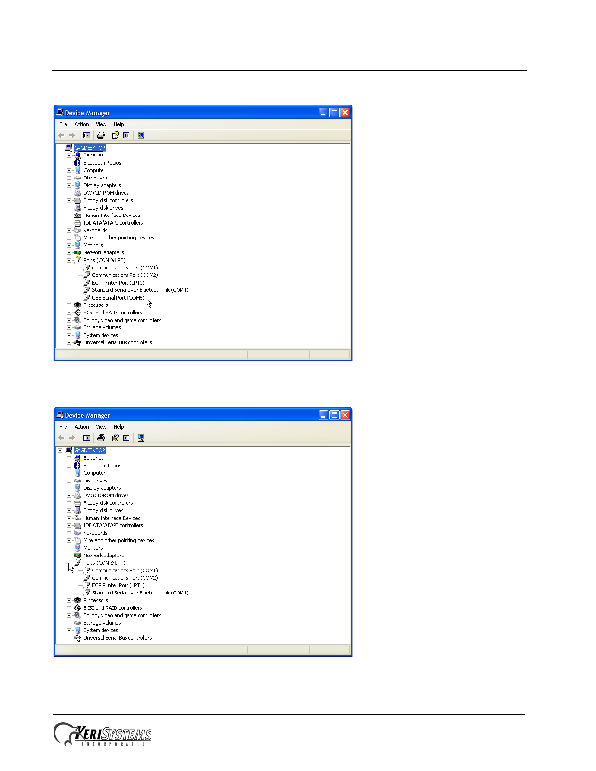
7. Open the Device Manager window:
- Start > Run > devmgmt.msc
Page 1 of 3 P/N: 01216-002 Rev. C
Page 2
Comm Board
Installation Guide
8. View the list of available COM ports.
9. Disconnect the USB cable and note the COM port that disappears. This is the COM port assigned to the Comm
Board.
10. Reconnect the USB cable and verify the COM port reappears with the same port assignment.
11. Note this COM port number assigned to the Comm Board for assignment in Doors.NET.
Page 2 of 3 P/N: 01216-002 Rev. C
Page 3

Comm Board
TB6
RS-485
Network
12 VDC
Power
Lock
Relay
Inputs
ADDRESS
POWER
NOISE
TP3
S1
LED 8
COMM
LED 9
TB1
GND
TP2
Reader Signal Strength
Test Points
TxRx -
TxRx +
Shield
+12 VDC
Negative
Earth Ground
Lock - NO
Lock - Common
Lock - NC
Door Switch - NC
Ground
RTE - NO
- not available Ground
Global Unlock - NO
Auxiliary RTE "A" - NO
Lithium
Battery
A-Reader B-Reader
JP10
Satellite Board Connectors
FUSE
TB5
1
2
3
4
5
6
7
7
1
2
3
4
5
6
TB3
1
2
3
4
TB2
1
3
2
1
2
3
Comm Board / LAN
Connectors
LED 1
485
JP9
LED12LED11
LED6
EPROM
LOCK
LINE1 LINE2
A & B Reader Wiring
(See Figure 2)
TB4
1
2
3
4
5
6
PIC - MIOP
Lock
Relay
- not available -
Seating Area for
Comm Board or LAN Unit
TB13TB14
Installation Guide
2.0 Seating the Comm Board
Seat the Comm Board into TB13 and TB14 as shown in the drawing below.
3.0 Contact Keri Systems
Keri USA Keri UK, Ireland, Europe
2305 Bering Drive
San Jose, CA 95131
T elephone: (800) 260-5265
(408) 435-8400
Fax: (408) 577-1792 Fax:+ 44 (0) 1763 274 106
Web: www.kerisys.com Web:www.kerisystems.co.uk
E-mail: sales@kerisys.com
techsupport@kerisys.com
end of document
Page 3 of 3 P/N: 01216-002 Rev. C
Park Farm Industrial Estate
Telephone: + 44 (0) 1763 273 243
E-mail:sales@kerisystems.co.uk
tech-support@kerisystems.co.uk
Unit 17
Ermine Street
Buntingford
Herts SG9 9AZ UK
 Loading...