

Page 1

BioPointe Reader
Installation Guide
What’s in this Guide
Installation Steps 1
Key Parts of the BioPointe Reader 2
Cabling Requirements 3
Power Connection 3
PXL-500W Wiegand Controller Connection 3
Serial Connection (RS232, RS485, or RS422) 3
Setting the DIP Switches (SW1, SW2, and SW3) 4
Connecting to the ADAM RS485 Converter 5
Connecting to LAN (Ethernet – TCP/IP) 5
Enrolling a Master User 7
Enrolling Additional Users 8
Mounting the BioPointe Unit 8
Getting Help 8
Installation Steps
Complete the following steps to install a BioPointe reader:
1. Connect the proper power.
2. Select and wire per the communication type desired.
a. Serial cable from the PC to one BioPointe reader
b. LAN connection to each BioPointe reader using LAN-50
devices
c. RS485 connection to one or more BioPointe readers using an
ADAM interface device
3. Set the DIP switches for the communication type selected.
4. Enroll a master user.*
5. Enroll additional users.*
6. Connect all BioPointe readers to Keri PXL-500W (Wiegan d )
controllers for door control.
7. Enroll users in the Doors program: Facility Code 0, User ID# as Card
Number, Wiegand card type.
8. Perform a Total Update in the Doors program to download all user
information to the Keri controllers.
*Note: These steps may be performed using BioPointe Central software.
Keri Systems, Inc.
1
www.kerisys.com
01956-001 Rev. A
Page 2
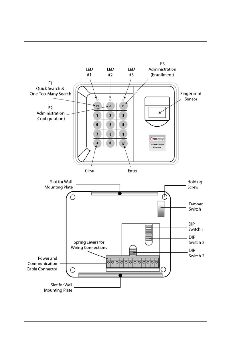
Key Parts of the BioPointe Reader
The keypad is made up of the standard numeric keys, three function keys, and
the ENTER and CLEAR keys.
The three DIP switches are used to set the device address, communication
type, and baud rate.
Keri Systems, Inc.
2
www.kerisys.com
01956-001 Rev. A
Page 3
Cabling Requirements
BioPointe RS485: Belden 9501, 24 AWG, twisted pair, shielded.
BioPointe to PXL: Belden 3124A, one pair 18 AWG (power); one pair
22 AWG (data), shielded.
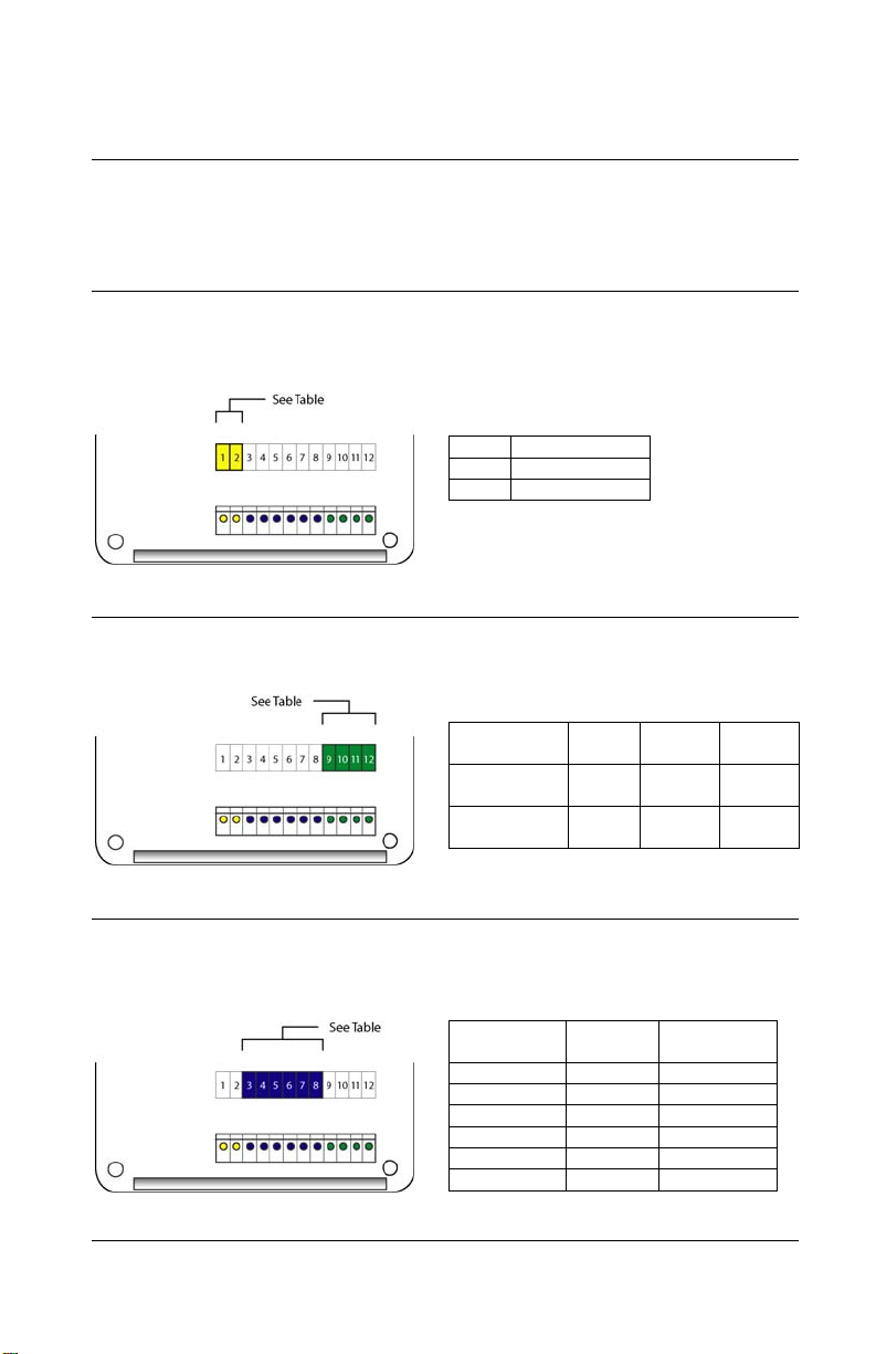
Power Connection
The BioPointe reader requires +12 to 24 VDC @ 500mA (~5w) at the reader.
If the power supply is located more than 100 feet from the reader, the wire
gauge you use must provide adequate power at the reader.
Pin Description
1 GND
2 12 to 24 VDC
PXL-500W Wiegand Controller Connection
The Wiegand output from a BioPointe reader to a Keri Wiegand controller is
connected as follows:
Wiegand
Line
BioPointe
Output
PXL-500W
TB5/TB6
W0 GND W1
Pin 9 Pin 10 Pin 11
Pin 1 Pin 4 Pin 7
Serial Connection (RS232, RS485, or RS422)
A DB-9F (female) connector is required to connect the BioPointe reader
directly to a PC using a serial connection. The drawings and tables below
show the pin-outs for each type of serial connection.
Keri Systems, Inc.
BioPointe
Pin
3-4-5GND5
6Rx3
7Tx2
8--
RS422 and RS485 pinouts are on the next page.
3
www.kerisys.com
RS-232 DB-9F Pin
01956-001 Rev. A
Page 4

Serial Connection (RS232, RS485, or RS422 – Cont.)
BioPointe
Pin
3Rx +2
4Rx -3
5-6Tx +4
7Tx -5
8--
RS422 DB-9F Pin
RS422 Connections
BioPointe
Pin
3-4-5-6D +3
7D -2
8--
RS485 DB-9F Pin
RS485 Connections
Setting the DIP Switches (SW1, SW2, and SW3)
Note: Cycle BioPointe reader power after changing any DIP switch settings so
the reader will recognize the DIP switch change.
The BioPointe reader has three DIP switches:
SW1 – Sets the Device ID
SW2 – Sets the baud rate and communications type
SW3 – Sets the serial interface type (RS232, RS422, or RS485)
SW1: 8 mini-switches to set Device ID from 1 to 254 – refer to the BioPointe
Device ID Addressing Table. Device ID 0 is reserved for TCP/IP – LAN- 50
devices. Device ID 255 is invalid.
SW2: 4 mini-switches, [1,2] SW2: 4 mini-switches, [3,4]
Baud Rate Communication Type
Baud Rate (Bps) Switch 1 Switch 2
38400 *
19200 - ON
9600 - 2400 ON -
* Default Value
ON ON
Comm Type Switch 3 Switch 4
RS232 *
Modem ON TCP/IP - ON
RS422/485 - -
* Default Value
ON ON
SW3: 8 mini-switches
Interface Type S1 S2 S3 S4 S5 S6 S7 S8
RS232 *
RS422 - ON ON - ON - ON RS485 ON - ON - ON - ON -
* Default Value
Keri Systems, Inc.
- - - ON - ON - ON
4
www.kerisys.com
01956-001 Rev. A
Page 5

Connecting to the ADAM RS485 Converter
The ADAM 4520 is an interface adapter, connected to the serial port of a PC
and converts data to RS485; you can then connect one or more BioPointe
devices to the ADAM. The ADAM requires 10-30 VDC, and is configured to
operate at 9600 baud. You can connect the ADAM to one, or more, BioPointe
readers.
ADAM Wiring Connections
Connecting to LAN (Ethernet – TCP/IP)
The BioPointe reader may be connected to a local area network (LAN) using a
Keri LAN-50 device. The LAN-50 should be assigned and addressed per the
instructions in the LAN-50/LAN-500 Application Note found on the Ker i CD
or the Keri web site. Set the Baud rate of the LAN-50 to 38400; when the
BioPointe is set for TCP/IP its baud rate defaults to 38400. The IP address
assigned to the LAN-50, and port number 10001, must also be set in the
BioPointe Central software by going to Tools \ Device Management System \
Device Connection Setup. Set for Ethernet, port number 10001, and the
TCP/IP address of the LAN-50 to which the reader is connected, then save the
configuration. Each BioPointe requires a LAN-50 unit.
Keri Systems, Inc.
5
www.kerisys.com
01956-001 Rev. A
Page 6

Connecting to LAN (Ethernet – TCP/IP – Cont.)
LAN-50 Wiring Connections
BioPointe Pin DB-25M Pin
57
63
72
DIP Switch Settings
SW1: Device ID
Device ID 0 is reserved for TCP/IP – LAN-50 devices. For LAN-50 operation,
set the BioPointe Device ID to 0 per the BioPointe Device ID Addressing
Table.
SW2: 4 mini-switches, [1,2] SW2: 4 mini-switches, [3,4]
Baud Rate Communication Type
Baud Rate (Bps) Switch 1 Switch 2
38400 * ON ON
19200 - ON
9600 - 2400 ON -
* Default Value
Comm Type Switch 3 Switch 4
RS232 ON ON
Modem ON -
TCP/IP * - ON
RS422/485 - -
* Required Value for LAN-50
SW3: 8 mini-switches
Interface Type S1 S2 S3 S4 S5 S6 S7 S8
RS232 * - - - ON - ON - ON
RS422 - ON ON - ON - ON RS485 ON - ON - ON - ON -
* Default Value
Keri Systems, Inc.
6
www.kerisys.com
01956-001 Rev. A
Page 7

Enrolling a Master User
When you first receive the device, there are no enrolled fingerprints. The first
person to enroll becomes the first master of the device.
1. Press [Circle] [Circle] [1]
The LEDs light up per the table below (refer to the Front of Unit drawing on
Page 2).
LED 1 LED 2 LED 3
Amber – Steady ON Red – Slow Blink Amber – Slow Blink
2. When LED 2 starts to blink slowly in red, enter a 4-digit ID. The 4-digit ID
is the User ID. When the User ID is accepted, LED 2 will blink fast in red as
shown below. The fingerprint sensor will also light up signifying it is ready to
read.
LED 1 LED 2 LED 3
Amber – Steady ON Red – Fast Blink Amber – Slow Blink
3. When the fingerprint sensor lights up, place your finger on it to begin the
enrollment process. Each successful enrollment requires two image captures.
After the first image has been successfully captured, the sensor will go off.
You will then hear a series of beeps acknowledging the read.
4. When you hear the series of beeps, lift up your finger and wait for the
sensor to light up a second time. Place your finger back on the sensor. If this
second capture image is successful; LED 1 will blink green briefly, then return
to amber.
LED 1 LED 2 LED 3
Green – Blink Once
Amber – Steady ON
You can enroll up to three fingerprints for each User ID. LED 2 will blink fast
in green in preparation for enrolling the next finger. Press [#] to continue, or
[*] to exit.
LED 1 LED 2 LED 3
Amber –Steady ON Green – Fast Blink Amber – Slow Blink
Keri Systems, Inc.
7
www.kerisys.com
01956-001 Rev. A
Page 8

Enrolling Additional Users
To enroll additional users, start from Step 1, but press [Circle] [Circle] [2] to
start enrollment. The rest of the steps are the same as those described above.
However, the third LED will blink differently to indicate the different
administration mode you are in.
Mounting the BioPointe Unit
Getting Help
The Keri CD contains software and documentation for all Keri products,
including the BioPointe User’s Ma n ual and BioPointe Central for Windows
Software Manual. Both manuals are also available on the Keri web site
www.kerisys.com.
Telephone technical support is available Monday through Friday, 6 AM to 5
PM Pacific Time, at 1-800-260-5265.
Keri Systems, Inc.
8
www.kerisys.com
01956-001 Rev. A
 Loading...