

Page 1
SERVICE MANUAL
MAT 1/3 RACK (EXCEPT 6-32)
POWER SUPPLY
KEPCO INC.
An ISO 9001 Company.
MAT 1/3 RACK
(EXCEPT 6-32)
MODEL
POWER SUPPLY
ORDER NO. REV. NO.
This on-line version of the Technical Manual
includes only Installation and Operating
Instructions. For the complete manual,
please contact Kepco.
©2004, KEPCO, INC
P/N 243-
KEPCO, INC. ! 131-38 SANFORD AVENUE ! FLUSHING, NY. 11352 U.S.A. ! TEL (718) 461-7000 ! FAX (718) 767-1102
KEPCO®
THE POWER SUPPLIER™
email: hq@kepcopower.com ! World Wide Web: http://www.kepcopower.com
Page 2

Declaration of Conformity
Application of Council directives:
Standard to which Conformity is declared:
EN61010-1:2001 (Safety requirements for electrical equipment for measurement,
control and laboratory use - Part 1)
Manufacturer's Name and Address:
Importer's Name and Address:
Type of Equipment:
Model No.:
73/23/EEC (LVD)
93/68/EEC (CE mark)
KEPCO INC.
131-38 SANFORD AVENUE
FLUSHING, N.Y. 11352 USA
P
O
C
E
V
I
T
A
T
N
E
S
E
R
P
E
R
Component Power Supply
[PRODUCT MODEL NUMBER]
Y
Year of Manufacture:
I, the undersigned, declare that the product specified above, when used in conjunction with the conditions of conformance set forth in the product instruction manual, complies with the requirements of the
Low Voltage Directive 73/23/EEC, which forms the basis for application of the CE Mark to this product.
Place: KEPCO Inc.
131-38 Sanford Ave.
Flushing, N.Y.11352 USA
Saul Kupferberg
(Full Name)
Date:
228-1348 DC-COMP/INST 112404
VP OF SALES
(position)
A
Page 3

Conditions of Conformance
When this product is used in applications governed by the requirements of the EEC, the following restrictions and conditions apply:
1. For European applications, requiring compliance to the Low Voltage Directive, 73/23/EEC, this power
supply is considered a component product, designed for "built in“ applications. Because it is incomplete in construction, the end product enclosure must provide for compliance to any remaining electrical safety requirements and act as a fire enclosure. (EN61010-1:2001, Cl. 6, Cl. 7, Cl.8, and Cl. 9)
2. This power supply is designed for stationary installation within an RA 50 or RA 51 rack adapter. Mains
power is supplied via a detachable power supply cord or via direct wiring to the source power terminal
block.
3. This power supply is considered a Class 1 (earthed) product. It is intended for use as part of equipment meant for test, measurement and laboratory use, and is designed to operate from single phase,
three wire power systems. This equipment must be installed within a suitably wired equipment rack,
utilizing a three wire (grounded) mains connection. See wiring section of this manual for complete
electrical wiring instructions. (EN61010-1:2001, Cl.6.10.1)
4. This power supply has secondary output circuits that are considered hazardous, and which exceed
240 VA at a potential of 2V or more.
5. The output wiring terminals of this power supply have not been evaluated for field wiring and, therefore, must be properly configured by the end product manufacturer prior to use.
6. This power supply employs a supplementary circuit protector in the form of a circuit breaker mounted
on the front panel. This circuit breaker protects the power supply itself from damage in the event of a
fault condition. For complete circuit protection of the end product, as well as the building wiring, it is
required that a primary circuit protection device be fitted to the branch circuit wiring. (EN610101:2001, Cl. 9.5)
7. Hazardous voltages are present within this power supply during normal operation. All operator adjustments to the product are made via externally accessible switches, controls and signal lines as specified within the product operating instructions. There are no user or operator serviceable parts within
the product enclosure. Refer all servicing to qualified and trained Kepco service technicians.
B
228-1373 COND/CONFORM 112404
Page 4
SAFETY INSTRUCTIONS
1. Installation, Operation and Service Precautions
This product is designed for use in accordance with EN 61010-1 and UL 3101 for Installation Category 2,
Pollution Degree 2. Hazardous voltages are present within this product during normal operation. The
product should never be operated with the cover removed unless equivalent protection of the operator
from accidental contact with hazardous internal voltages is provided:
!
!
!
There are no operator serviceable parts or adjustments within the product enclosure.
Refer all servicing to trained service technician.
Source power must be removed from the product prior to performing any servicing.
This product is factory-wired for the nominal a-c mains voltage indicated on the rating nameplate located adjacent to the source power connection on the product's rear
panel. To reconfigure the product input for other nominal mains voltages as listed
herein, the product must be modified by a trained service technician.
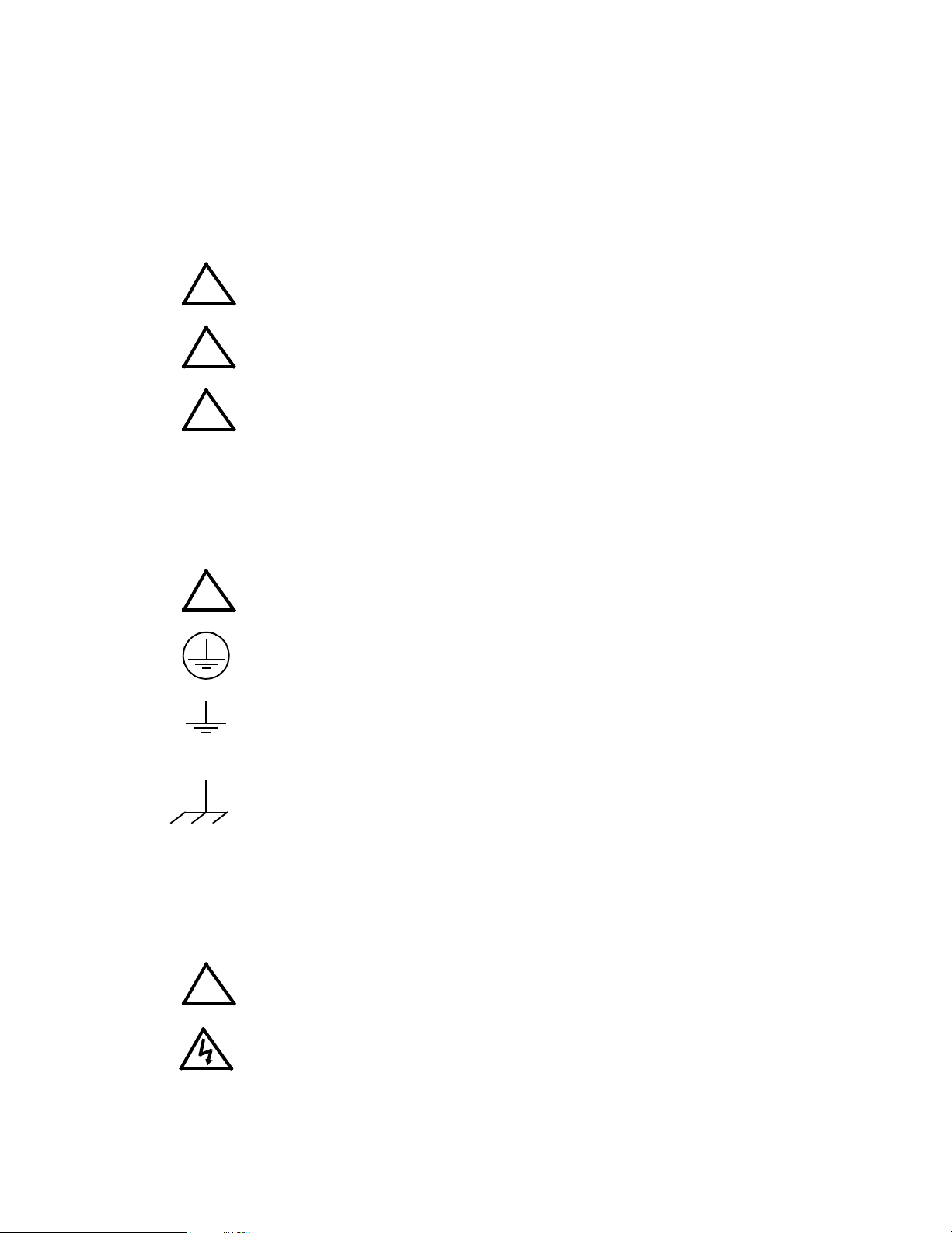
2. Grounding
This product is a Class 1 device which utilizes protective earthing to ensure operator safety.
The PROTECTIVE EARTHING CONDUCTOR TERMINAL must be properly con-
!
nected prior to application of source power to the product (see instructions on installation herein) in order to ensure safety from electric shock.
PROTECTIVE EARTHING CONDUCTOR TERMINAL - This symbol indicates the
point on the product to which the protective earthing conductor must be attached.
EARTH (GROUND) TERMINAL - This symbol is used to indicate a point which is
connected to the PROTECTIVE EARTHING TERMINAL. The component installer/
assembler must ensure that this point is connected to the PROTECTIVE EARTHING TERMINAL.
CHASSIS TERMINAL -This symbol indicates frame (chassis) connection, which is
supplied as a point of convenience for performance purposes (see instructions on
grounding herein). This is not to be confused with the protective earthing point, and
may not be used in place of it.
3. Electric Shock Hazards
This product outputs hazardous voltage and energy levels as a function of normal operation. Operators
must be trained in its use and exercise caution as well as common sense during use to prevent accidental
shock.
This symbol appears adjacent to any external terminals at which hazardous voltage
!
228-1352 SAFETY - (COVER REMOVAL) 112404 C/(D BLANK)
levels as high as 500V d-c may exist in the course of normal or single fault conditions.
This symbol appears adjacent to any external terminals at which hazardous voltage
levels in excess of 500V d-c may exist in the course of normal or single fault conditions.
Page 5

Page 6

TABLE OF CONTENTS
SECTION PAGE
SECTION 1 - INTRODUCTION
1.1 Scope Of Manual..................................................................................................................................... 1-1
1.2 General Description................................................................................................................................. 1-1
1.3 Specifications, Electrical.......................................................................................................................... 1-3
1.4 DC Output Ratings For 1/3, 2/3 And Full Rack Modules....................................................................... 1-4
1.5 Miscellaneous Features ......................................................................................................................... 1-7
1.6 Accessories ............................................................................................................................................. 1-7
1.7 Safety ...................................................................................................................................................... 1-8
SECTION 2 - INSTALLATION
2.1 Unpacking And Inspection....................................................................................................................... 2-1
2.2 Transport instructions.............................................................................................................................. 2-1
2.3 Terminations............................................................................................................................................ 2-2
2.4 AC Input Requirement............................................................................................................................. 2-5
2.5 Cooling .................................................................................................................................................... 2-6
2.6 Installation ............................................................................................................................................... 2-6
2.7 Grounding................................................................................................................................................ 2-7
2.7.1 Safety Grounding............................................................................................................................... 2-7
2.7.2 DC (Output) Grounding...................................................................................................................... 2-8
2.7.3 Power Module To Load Interface..................................................................................................... 2-8
2.7.4 Load Connection, Local Error Sensing.............................................................................................. 2-9
2.7.5 Load Connection With Remote Error Sensing................................................................................... 2-10
2.8 Operating Configuration .......................................................................................................................... 2-10
2.9 Preliminary Check-out............................................................................................................................. 2-11
2.9.1 Example 1: Full Scale Voltage Check................................................................................................ 2-12
2.9.2 Example 2: Full Scale Current Check............................................................................................... 2-13
2.9.3 Example 3: To Reset the Power Module ........................................................................................... 2-14
SECTION 3 - OPERATION
3.1 General.................................................................................................................................................... 3-1
3.2 Series Connection Of MAT Power Modules............................................................................................ 3-1
3.3 Power Module Controller/MAT Time Delays (To Obtain A Valid Status):................................................ 3-1
3.4 Power Loss Circuit .................................................................................................................................. 3-2
3.5 Introduction To Controlling The MAT Power Module Output................................................................... 3-2
3.5.1 MAT/Power Module Controller System.............................................................................................. 3-4
3.5.2 MAT/TMA Pc-27 System................................................................................................................... 3-5
3.6 Remote Programming ............................................................................................................................. 3-6
3.6.1 General.............................................................................................................................................. 3-6
3.6.2 SCPI Programming............................................................................................................................ 3-6
3.6.2.1 SCPI Program Example............................................................................................................... 3-7
3.6.3 CIIL Programming.............................................................................................................................. 3-8
3.6.3.1 Examples Using CIIl To Program The MAT Power Module......................................................... 3-8
3.6.3.1.1 Example 1: Program Positive Voltage With Current Limit......................................................3-8
3.6.3.1.2 Example 2 : Program Negative Voltage With Current Limit ...................................................3-10
3.6.3.1.3 Example 3: Program Current And Voltage Limit .....................................................................3-11
APPENDIX A - CIIL COMMAND DEFINITIONS
MAT 25-14 112404
i
Page 7

LIST OF FIGURES
FIGURE TITLE PAGE
1-1 Remotely Controlled Power Supply Configurations Using Kepco Products............................................... 1-2
1-2 MAT Power Module Mechanical Outline Drawing...................................................................................... 1-6
1-3 The TMA 4882-27 Controller And MAT Power Modules............................................................................ 1-8
2-1 Front View Of The 1/3 Rack MAT Power Supply ...................................................................................... 2-3
2-2 Rear View Of The 1/3 Rack Power Module............................................................................................... 2-4
2-3 MAT Module Barrier Strip With Jumpers For 115 Or 230 Va-c ............................................................... 2-6
2-4 Variation Of Output Impedance With Frequency For A Voltage Source And A Current Source................ 2-8
2-5 Load Connections, Local Sensing.............................................................................................................. 2-9
2-6 Load Connections, Remote Sensing.......................................................................................................... 2-10
3-1 Two MAT 1/3 RACK Power Modules Connected In Series Via Their Output Connector......................... 3-2
3-2 MATPower Module Control Section, Top Cover Removed ........................................................................ 3-3
3-3 Tree Diagram of SCPI Commands Used with MAT Power Supplies ......................................................... 3-6
3-4 Typical Example Of MAT Power Supply Program Using SCPI Commands............................................... 3-7
3-5 Schematic Diagram MAT Front Panel Display Board A8.......................................................................... 3-13
A-1 FNC — Function Command....................................................................................................................... A-1
A-2 INX — Initiate Op Code Command ............................................................................................................ A-2
A-3 FTH — Fetch Command ............................................................................................................................ A-2
A-4 SET Command........................................................................................................................................... A-3
A-5 OPN, CLS — Open, Close Relay Commands ........................................................................................... A-4
A-6 RST — Reset Command............................................................................................................................ A-4
A-7 CNF, IST — Confidence Test, Internal Self Test Commands .................................................................... A-4
A-8 STA — Status Command........................................................................................................................... A-5
ii
MAT 25-14 112404
Page 8

LIST OF TABLES
TABLE TITLE PAGE
1-1 MAT Power Module Features And Specifications .......................................................................................1-3
1-2 MAT Power Modules Power Output Ratings ...............................................................................................1-4
1-3 Safety Symbols ...........................................................................................................................................1-8
2-1 Hardware Required for Reshipment in Transport Cover .............................................................................2-1
2-2 Internal Controls Accessible Through Top Cover .......................................................................................2-2
2-3 Front Control MAT Power Module ..............................................................................................................2-3
2-4 Rear Terminations MAT Power Module ......................................................................................................2-4
2-5 Ac Input/Control Bus Connector Pin Designations .....................................................................................2-4
2-6 DC Output Connector Pin Designations .....................................................................................................2-5
2-7 Internal Jumper Configuration .....................................................................................................................2-11
3-1 Device Address Selection For The MAT power Module .............................................................................3-4
A-1 CIIL Subsystem Command/query Index .................................................................................................... A-1
A-2 CIIL Error Messages ..................................................................................................................................A-5
MAT 25-14 112404
iii/(vi Blank)
Page 9

Page 10

1.1 SCOPE OF MANUAL
This manual contains instructions for the installation, operation, and maintenance of the 1/3
Rack size 360W MAT series of voltage and current stabilized DC Power Modules manufactured
by Kepco, Inc. Flushing, New York, U.S.A.
1.2 GENERAL DESCRIPTION
The Kepco MAT Power Module with overvoltage, overcurrent, overtemperature, polarity reversal, and power loss protection is a digitally controlled precision stabilized Power Module that
delivers either stabilized voltage or current. A single front panel meter with a selector switch
constantly monitors the output voltage or the output current. The prevailing operating mode is
indicated by LED mode indicators on the front panel. Operating mode crossover is dependent on
commands from a Host Computer. The Power Module has a linear and fully dissipative NPN
pass transistor driven by high gain integrated circuit amplifiers. The output of the Power Module
is fully programmable.
The Power Module features full range output control by means of a compatible Kepco Power
Module Controller. Control of the MAT Power Module is via the IEEE 1118 2-wire serial bus
operating at 375KHz; as many as 27 separate modules of either the MAT, MST, MBT or BOP
Series design can be addressed via the bus (see Figure 1-1). Decoders for RS232, IEEE-488
and VXI are available in modular form and stand-alone types. As shown in Figure 1-1, the following controllers are available to control of MAT Power Modules directly from a computer.
SECTION 1 - INTRODUCTION
a. Controller Model TMA PC-27 plugs into a half-card slot of a DOS-based PC and allows key-
board control of the MAT via the IEEE 1118 bus.
b. Controller Model TMA 4882-27 is free-standing and allows host computers designed for
RS232 or IEEE 488 bus communication to control the MAT via the IEEE 1118 bus.
c. Controller Model TMA-VXI-27 plugs into a slot in a VXI chassis and allows VXI-based com-
puters to control the MAT via the IEEE 1118 bus.
d. Controller Model MST 488-27 plugs into a slot in a Model RA 55 Rack Adapter and allows
host computers designed for RS232 or IEEE 488 bus communication to control the MAT via
the IEEE 1118 bus.
e. The MAT Power Module can also be directly controlled via the keypad of the MBT Series
(“G” Option) Power Supply via the IEEE 1118 bus.
An important feature of the MAT Series Power Module is the overvoltage and overcurrent protection circuits. This protection is provided by two autotracking amplifiers that have an overvoltage and overcurrent tracking range of 10% ± 3% above the programmed Power Module output
voltage or current.
The MAT series Power Modules are built in 1/3 Rack, 2/3 Rack and Full Rack mechanical sizes
according to their approximate output power rating (see Mechanical Outline Drawing of the
Power Module Chassis, Figure 1-2).
Power transistors and drivers on all Power Module designs are mounted on highly efficient patented heat sink assemblies that are cooled by fans.
MAT 1/3 and 2/3 Rack size modules are designed to operate in either one of two housings
called RA 50 and RA 51. RA 50 is 5-1/4" x 19" x 25" and accepts up to three 1/3 Rack Power
Modules. RA 51 is similarly sized, but configured for one 1/3 Rack Module and one 2/3 Rack
Module. Full Rack MAT Power Modules mount directly into a standard 19 inch Equipment Rack.
MAT 1/3 RACK/ 112404
1-1
Page 11
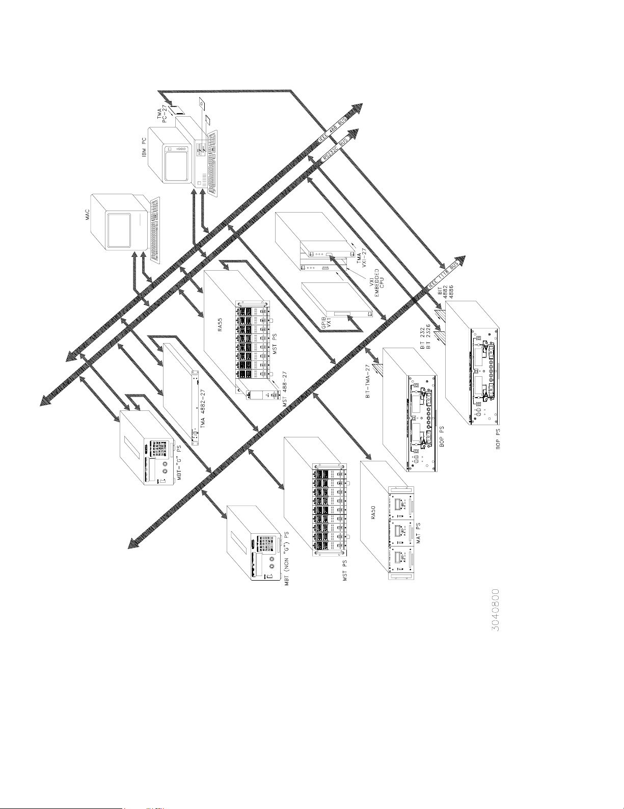
FIGURE 1-1. REMOTELY CONTROLLED POWER SUPPLY CONFIGURATIONS USING KEPCO PRODUCTS
1-2
MAT 1/3 RACK/ 112404
Page 12

1.3 SPECIFICATIONS, ELECTRICAL
a) MAT Power Module Features And Specification
TABLE 1-1. MAT POWER MODULE FEATURES AND SPECIFICATIONS
PARAMETER CONDITION
Input Voltage Range
Input Current Max
Input Frequency RANGE 47-63 Hz
Voltage/Current Adjust-
ment Range
Programming
Resolution
Programming Accuracy
Data Read Back
Accuracy via Digital Bus
Source Effect
Load Effect
Time 8 Hour Drift
Temperature
Coefficient/°C
Ripple & Noise
Transient Recovery Voltage
Temperature
Cooling Built-in fan, air exhaust to rear
Remote Sensing Range 0.5 volts per lead (Provision for 4-terminal connection to load)
DC Output Isolation Voltage 500 Vdc
Leakage Current Output to chassis 5
Series/Parallel Operation Consult Kepco application engineering
Output Display
IndIcators 4 LEDs
Output Enable/Disable
Polarity Reversal
USER
SELECTABLE
115 VAC 7.0A 14.0A 21.0A
230 VAC 3.5A 7.0A 10.5A
RANGES
Voltage 0.024% Eo max (12 bits)
Current 0.024% Io max (12 bits)
Voltage 0.024% Eo max
Current 0.1% Io max
Volt ag e 0.1% Eo m ax
Current 0.12% Io max
Voltage 0.001% Eo max
Current 0.005% Io max
Voltage 0.002% Eo max
Current 0.024% Io max or 4 mA (whichever is greater)
Voltage 0.01% Eo max
Current 0.02% Io max
Voltage 0.01% Eo max
Current 0.02% Io max
Volt ag e
Current
Operating 0 to 50 °C
Storage -20 to +70 °C
3-1/2 digit LCD
Panel Meter
1/3 RACK 2/3 RACK FULL RACK
0 to 100% of rating, by preprogrammed setting,
rms: 0.001% Eo max or 0.3 mV (whichever is greater)
p-p: 0.01% Eo max or 3 mV (whichever is greater)
150
sec to recover within 0.1% Eo max for 10% to 100%
µ
Voltage and Current Mode,Output Enabled, Polarity
Reversed
Built in power and sensing relays controlled through IEEE
1118 b us
Built in power and sensing relays controlled through IEEE
1118 b us
MAT POWER MODULE
105-125 VAC
210-250 VAC
within inherent resolution limits
rms: 0.03% Io max
p-p: 0.3% Io max
step in rated load current
A rms or 50µA p-p @ 115V a-c
µ
Switch selectable voltage/current
MAT 1/3 RACK/ 112404
1-3
Page 13

TABLE 1-1. MAT POWER MODULE FEATURES AND SPECIFICATIONS (CONTINUED)
PARAMETER CONDITION
Overvoltage Tracks program voltage, Crowbars output and turns off input
Overcurrent Tracks program current, Crowbars output and turns off input
Protection
Source Connections
Load Connections
Remote Control
Signal Connections
Dimensions See Figure 1-2.
Weight LBS336075
Mounting Front
Filler Panels
Overtemperature
Polarity Reversal Built in diodes protect unipolar supply output
Power Loss Detects loss of ac input power, disables output
For either RA 50
or RA 51
1/3 RACK 2/3 RACK FULL RACK
Monitors heat sink temperature, Crowbars output and turns
off input
3-wire power entry, via user-configurable mating connector
(supplied) and proper gage wires (not supplied)
5-wire connection, via user-configurable mating connector
(supplied) and proper gage wires (not supplied)
DC Power Output: 2 wires
Output Sense Terminals: 2 wires
Ground: 1 wire
Two 2-wire connections via user-configurable mating
connector supplied and 22 AWG wire (not supplied).
Connectors in parallel for daisy chaining multiple power
supplies (full rack only).
Three 1/3 rack
modules plug into
RA 50. One 1/3
and one 2/3 rack
modules plug into
RA 51
MAT POWER MODULE
One 1/3 and one
2/3 rack modules
plug into RA 51
RFP 50-1: 1/3 Panel
RFP 50-2: 2/3 Panel.
Full Rack mounts
directly into 19
inch Rack
1.4 DC OUTPUT RATINGS FOR 1/3, 2/3 AND FULL RACK MODULES
a. MAT Power Module DC Output Ratings 1/3, 2/3, and Full Rack Size - see Table 1-2
b. Output range:
1) Voltage mode: 0-100% of rated voltage
2) Current mode: 0-100% of rated current
TABLE 1-2. MAT POWER MODULES POWER OUTPUT RATINGS
360W MODULES-1/3 RACK SIZE-DC OUTPUT RATINGS
MODEL VOLTS AMPS POWER
MAT 6-32 0-6 0-32 192
MAT 15-20 0-15 0-20 300
MAT25-14 0-25 0-14 350
MAT 36-10 0-36 0-10 360
MAT 55-7 0-55 0-7 385
MAT 75-5 0-75 0-5 375
MAT 100-3.6 0-100 0-3.6 360
MAT 150-2.4 0-150 0-2.4 360
1-4
MAT 1/3 RACK 112404
Page 14

TABLE 1-2. MAT POWER MODULES POWER OUTPUT RATINGS
360W MODULES-1/3 RACK SIZE-DC OUTPUT RATINGS
720W MODULES-2/3 RACK-DC OUTPUT RATINGS
MODEL VOLTS AMPS POWER
MAT 6-64 0-6 0-64 384
MAT 15-40 0-15 0-40 600
MAT25-28 0-25 0-28 700
MAT 36-20 0-36 0-20 720
MAT 55-14 0-55 0-14 770
MAT 75-10 0-75 0-10 750
MAT 100-7.2 0-100 0-7.2 720
MAT 150-4.8 0-150 0-150 720
1080W MODULES-FULL RACK-DC OUTPUT RATINGS
MODEL VOLTS AMPS POWER
MAT 6-100 0-6 0-100 600
MAT 15-60 0-15 0-60 900
MAT 25-42 0-25 0-42 1050
MAT 36-30 0-36 0-30 1080
MAT 55-20 0-55 0-20 1100
MAT 75-15 0-75 0-15 1125
MAT 100-10 0-100 0-10 1000
MAT 150-7 0-150 0-7 1050
MAT 1/3 RACK/ 112404
1-5
Page 15
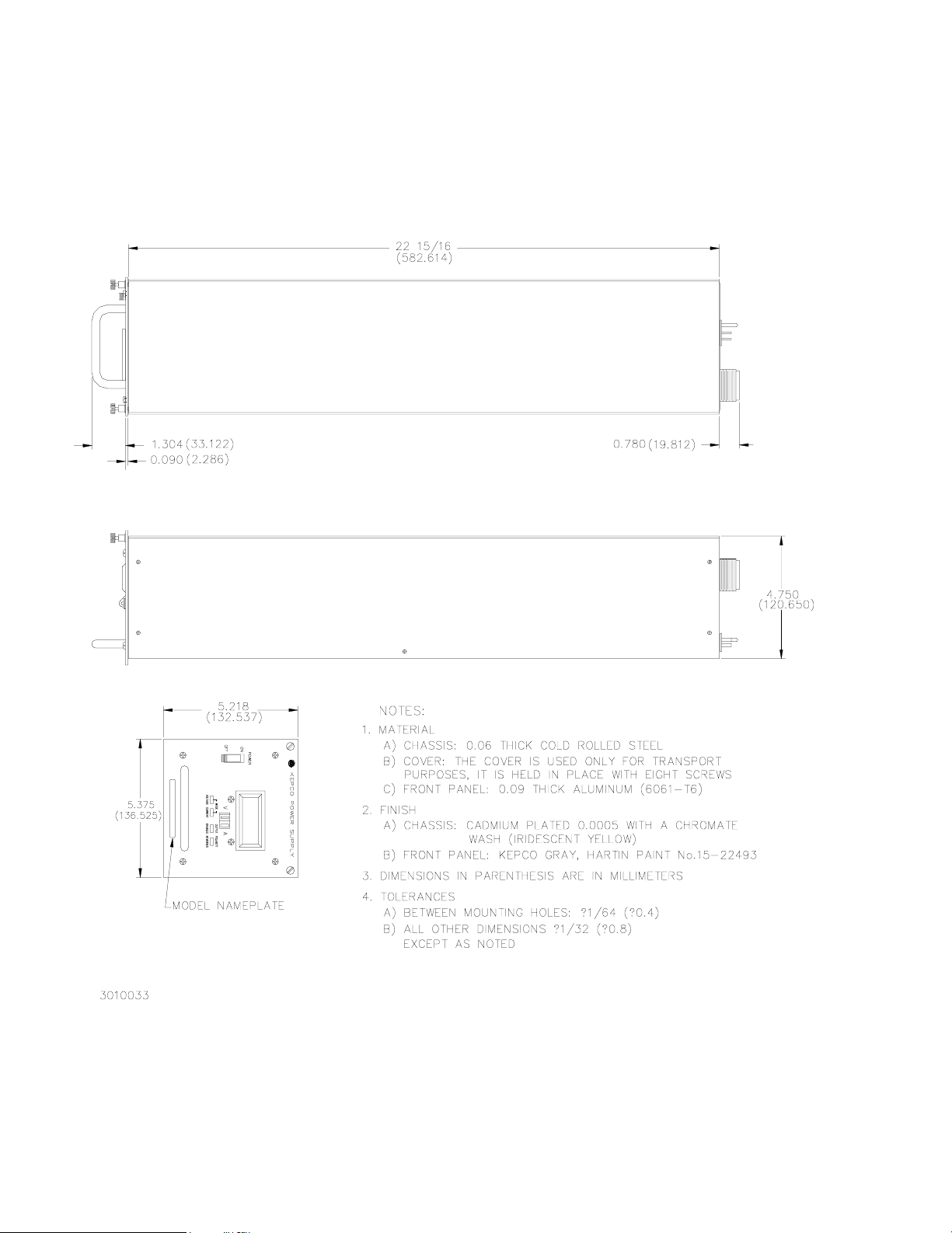
FIGURE 1-2. MAT POWER MODULE MECHANICAL OUTLINE DRAWING
1-6
MAT 1/3 RACK 112404
Page 16

1.5 MISCELLANEOUS FEATURES
a. Mode flag: A pair of panel LED indicators indicate whether the Power Module is in voltage
mode or in current mode.
b. Remote error sensing: Separate voltage-sensing terminals permit 4-wire connections to a
load to compensate for static load effects (up to 0.5V per lead). An additional 1 volt output
voltage, beyond the nominal voltage rating of each MAT Power Module, is provided for this
purpose.
c. Storage temperature range: -20 to +85° C.
d. Cooling: The fans are high efficiency, single bearing fans with special low-noise non-metallic
blades
1.6 ACCESSORIES
NOTE: All Kepco rack adapters fit standard EIA rack dimensions. They are drilled for chassis
slides (see the RA 50 or RA 51 manual).
a. Kepco Rack Adapter Model RA-50 is for three 1/3 Rack Size Power Modules. Filler panels
are available to cover empty slots, if the adapter is not used to its full capacity.
b. Kepco Rack Adapter Model RA-51 is for one 1/3 Rack Size, and one 2/3 Rack Size Power
Modules. Filler panels to cover empty slots are available if the adapter is not used to its full
capacity. The Full Rack MAT Power Modules fit directly into a standard 19 inch Rack.
c. One 2 meter long shielded twisted pair cable with two mating connectors, one at each end
(Kepco P/N 118-0699) is supplied with each Rack Adapter (RA 50 or RA 51) and with each
Full Rack MAT Power Module. The Power Module Controller (see PAR. 1.2) and up to 27
MAT Power Modules can be connected in a daisy chain configuration as shown in FIG. 1-3.
The last (in the daisy chain) Power Module Control Bus Outlet must be terminated with a Terminating Connector Assembly (Kepco P/N 195-0075) that is supplied with the Power Module Controller.
MAT 1/3 RACK/ 112404
1-7
Page 17

FIGURE 1-3. THE TMA 4882-27 CONTROLLER AND MAT POWER MODULES
1.7 SAFETY
There are no operator serviceable parts inside the case. Service must be referred to authorized
personnel. Using the power supply in a manner not specified by Kepco. Inc. may impair the protection provided by the power supply. Observe all safety precautions noted throughout this manual. Table 1-3 lists symbols used on the power supply or in this manual where applicable.
TABLE 1-3. SAFETY SYMBOLS
SYMBOL Meaning
CAUTION: RISK OF ELECTRIC SHOCK.
CAUTION: REFER TO REFERENCED PROCEDURE.
!
1-8
WARN ING
CAUTION
INDICATES THE POSSIBILITY OF BODILY INJURY
OR DEATH.
INDICATES THE POSSIBILITY OF EQUIPMENT
DAMAGE.
MAT 1/3 RACK 112404
Page 18

SECTION 2 - INSTALLATION
2.1 UNPACKING AND INSPECTION
This instrument has been thoroughly inspected and tested prior to packing and is ready for
operation. After careful unpacking, inspect for shipping damage before attempting to operate.
Perform the preliminary operational check as outlined in PAR 2.9 If any indication of damage is
found, file an immediate claim with the responsible transport service.
The MAT 1/3 rack module may be received in either of two ways; with a special transport cover
or in a RA 50 or RA 51 housing. Below are the procedures necessary to remove the MAT power
module from its housing or transport cover
a. For the MAT 1/3 rack power module in a transport cover, there are ten screws (self tap-
ping countersunk Flat Head Phillips size no. 6-32 x 3/8, Kepco P/N 101-0344) located
at each side of the transport cover. These screws must be removed and saved with the
cover for later transport use.
NOTE: If the Power Modules are shipped in the RA 50 or RA 51 Rack Adapter, the power
modules must be removed before installing the rack adapter in a rack.
b. To remove the 1/3 rack power module from the RA 50/RA 51 housing, loosen the two
slotted captive thumb screws on the front panel, then remove and save the six Flat
Head Phillips screws from the base of the housing. Slide the power module out of the
housing and set the Control Bus Address (see PAR. 3.5). Slide the power module back
into the housing and fasten the two slotted captive thumb screws It is not advisable to
replace the six Flat Head Phillips screws in the base of the housing unless the unit is
going to be transported.
2.2 TRANSPORT INSTRUCTIONS
THE MAT POWER MODULE SHOULD BE SHIPPED ONLY IN THE RACK
ADAPTER OR IN A TRANSPORT COVER. FAILURE TO PROPERLY
SECURE THE MAT POWER MODULE BEFORE SHIPPING WILL RESULT
IN SEVERE DAMAGE TO THE EQUIPMENT AND VOID THE WARRANTY.
The MAT Power Module is a relatively heavy piece of equipment, particularly due to the main
Power Transformer, chassis frame and electrolytic capacitors. This means that the unit when
shipped, must be properly fastened in a transport cover, rack adapter or by other means; otherwise the Power Module may buckle at the center of gravity of the chassis due of its weight.
To transport the MAT Power Module in the transport cover (supplied with the unit) secure the
power module with 6-32 steel round head phillips screws (see Table 2-1).
TABLE 2-1. HARDWARE REQUIRED FOR RESHIPMENT IN TRANSPORT COVER
FOR THESE MAT
POWER MODULES
1/3 RACK 129-0231 QTY 10 N/A
2/3 RACK 129-0232 QTY 14 QTY 2
USE THIS TRANSPORT COVER
KEPCO P/N
To transport the MAT Power Module in the Rack Adapter RA 50/ RA 51, secure each Power
Module with Flat Head Phillips screws (self tapping countersunk Flat Head Phillips size no.
8-5/8, Kepco P/N 101-0421), six for 1/3 rack models and eight for 2/3 rack models.
MAT 1/3 RACK/ 112404
CAUTION
6-32 x 3/8
(KEPCO P/N 101-0344)
USE THESE SCREWS
6-32 x 3/4
(KEPCO P/N 101-0349
2-1
Page 19

If a transport cover is not available, the MAT power module may be mounted on a 3/4 inch thick
(or greater) piece of wood by using 8-18 thread-forming screws with a type B style point. A
screw should be used to secure the wood to each of the mounting grommets in the bottom of
the chassis.
2.3 TERMINATIONS
1. Internal Calibration Controls: Refer to Table 2-2 and Figure 3-2.
2. Front Panel: Refer to Table 2-3 and Figure 2-1.
3. Rear Panel: Refer to Table 2-4 and Figure 2-2.
TABLE 2-2. INTERNAL CONTROLS ACCESSIBLE THROUGH TOP COVER
REFERENCE
DESIGNATION
A1R28 I
A1R20 E
A1R15 I
A1R16 I
A1R11 V
A1R12 I
A3S1 Node Address Used to select Node address (node number or channel number) of the
A1TP1 Test Points Provides four test points used for testing/calibration
NOTES:
1. These adjustments must be done in accordance with the calibration procedure (see PAR. 5.5).
O ZERO
O ZERO
CURRENT SENSING ZERO
FULL SCALE CURRENT ADJUST
(NOTE 1)
REF
REF
CONTROL PURPOSE
(NOTE 1) Used to adjust output current of power supply to initial value.
CONDITIONS: current mode, shunt at the output.
(NOTE 1) Used to adjust output voltage of power supply to zero.
CONDITIONS: voltage mode, no load.
(NOTE 1) Used to adjust current monitor amplifier to zero.
CONDITIONS: voltage mode, no load.
Used to calibrate the full scale value of the output current.
CONDITIONS: current mode, shunt at the output.
(NOTE 1) Used to calibrate full scale voltage.
CONDITIONS: voltage mode, no load.
(NOTE 1) Used to adjust internal full scale current.
CONDITIONS: current mode, shunt at the output.
MAT Power Supply from 1 - 31
1 -CURRENT REFERENCE
2 -CURRENT MONITOR
3 - VOLTAGE REFERENCE
4 - COMMON
2-2
MAT 1/3 RACK/ 112404
Page 20

FIGURE 2-1. FRONT VIEW OF THE 1/3 RACK MAT POWER SUPPLY
TABLE 2-3. FRONT CONTROL MAT POWER MODULE
ITEM NO.
(See Fig. 2-1)
1 AC POWER SWITCH/CIRCUIT BREAKER
2 VOLTAGE MODE INDICATOR, GREEN LED ENERGIZED IN VOLTAGE MODE
3 CURRENT MODE INDICATOR, YELLOW LED ENERGIZED IN CURRENT MODE
4
5 OUTPUT ENABLED INDICATOR, GREEN LED
6 POLARITY REVERSED INDICATOR, GREEN LED
VOLTAGE/CURRENT METER WITH SELECTION
SWITCH, GREEN LED/ YELLOW LED
CONTROL FUNCTION
SERVES AS AN AC POWER SWITCH AND
TURNS THE AC POWER LINE OFF ON OVERVOLTAGE, OVERCURRENT, OVERTEMPERATURE OR POWER LOSS.
ENERGIZES TO READ OUTPUT VOLTAGE
ENERGIZES TO READ OUTPUT CURRENT
ENERGIZED WHEN RELAY CLOSES AND
VOLTAGE IS PRESENT AT THE POWER MODULE OUTPUT TERMINALS
ENERGIZED WHEN RELAY CLOSES AND
POLARITY AT POWER MODULE OUTPUT
TERMINALS IS REVERSED
MAT 1/3 RACK/ 112404
2-3
Page 21

FIGURE 2-2. REAR VIEW OF THE 1/3 RACK POWER MODULE
TABLE 2-4. REAR TERMINATIONS MAT POWER MODULE
ITEM NO.
(See Fig. 2-2)
1 DC OUTPUT CONNECTOR
2
REAR TERMINATION FUNCTION
AC INPUT POWER/CONTROL
BUS CONNECTOR
TABLE 2-5. AC INPUT/CONTROL BUS CONNECTOR PIN DESIGNATIONS
CONNECTOR PIN
(See Figure 2-2)
1 SAFETY GROUND
2 AC “H” (HOT)
3 AC “N” (NEUTRAL)
4 NOT USED
Connects the MAT power module output lines, sensing lines and
ground line to the load (See Table 2-6 for pin designations.) Type
MS3102A16-10P, (mating connector MS3108A16--10S, KEPCO
P/N 143-0331, supplied).
Connects MAT power module to a-c input power source and Bitbus
controller via RA 50 or RA 51 rack adapter. Five pins are used for
ac input, two for control bus connections (see Table 2-5). The
power module controller and up to 27 MAT power modules can be
connected (daisy chained) to the control bus (see PAR. 1.2).
FUNCTION
2-4
5 CONTROL BUS (IEEE 1118 BUS) LINE
6 CONTROL BUS (IEEE 1118 BUS) LINE
MAT 1/3 RACK/ 112404
Page 22

TABLE 2-6. DC OUTPUT CONNECTOR PIN DESIGNATIONS
CONNECTOR PIN
(See Figure 2-2)
H CONNECTED TO OUTPUT TERMINAL 1
I CONNECTED TO OUTPUT TERMINAL 2
A CONNECTED TO SENSE TERMINAL 1
E CONNECTED TO SENSE TERMINAL 2
D CONNECTED TO SAFETY GROUND
2.4 AC INPUT REQUIREMENT
These Power Modules operate on a single phase, 115 Va-c nominal line. The Power Module
can also be connected to 230 Va-c by the following procedure:
1. Disconnect the AC Input power from the RA 50 or RA 51 rack adapter
Turn OFF the circuit breaker on the module (if operating).
2. Remove the MAT Power Module from the RA 50 or RA 51 Rack Adapter by loosening two
slotted captive screws at the top of the MAT front panel, then locate the barrier terminal
block mounted on the chassis.
FUNCTION
NOTE: Do not move the wires connected to the barrier strip, they are properly placed for both
115 Va-c and 230 Va-c operation.
3. Figure 2-3A shows the barrier terminal block set to 115 Va-c
operation. Remove the jump-
ers on the barrier strip connecting terminals 2 to 3, and terminals 4 to 5.
4. Place a jumper between terminals 3 and 4. For 230 Va-c the barrier strip appears as in Figure 2-3B.
5. Verify that the source voltage on the Rack Adapter matches that of the Power Module.
6. Return the Module to the Rack Adapter
NOTE: To return to 115 Va-c operation reverse the procedure. Remove the jumper in step 4 and
replace the jumpers in step 3.
MAT 1/3 RACK/ 112404
2-5
Page 23

FIGURE 2-3. MAT MODULE BARRIER STRIP WITH JUMPERS FOR 115 OR 230 VA-C
2.5 COOLING
The power transistors and rectifiers in the MAT Power Module are maintained within their operating temperature range by means of special heat sink assemblies, cooled by an internal fan.
SIDE PANEL OPENINGS AND THE TOP OF THE CASE MUST BE KEPT CLEAR FROM
OBSTRUCTIONS TO ENSURE PROPER AIR CIRCULATION. If the MAT Power Module is
rack mounted, or installed in confined spaces, care must be taken that the ambient temperature
(the temperature immediately surrounding the Power Module) does not rise above the limit
specified in Table 1-1.
2.6 INSTALLATION
If the unit is to be rack mounted install the RA 50 or RA 51 Rack Adapter in the rack per Rack
Adapter instruction manual. Install the MAT 1/3 Rack Power Module in the Rack Adapter housing and secure with two front panel slotted screws. Refer to Rack Adapter manual for electrical
connections of the rack adapter.
The following steps are recommended for inserting the Power Module into the Rack Adapter.
• Tilt the front of the Power Module slightly lower then the rear, set the two rearmost grommets of the Module on the front lip of the Rack Adapter opening.
• Lift the front of the Module until the bottom is approximately parallel to the bottom of the
Rack Adapter and gently begin slidding in the Module, maintaining support with both
hands as needed to prevent the bottom of the Module from scrapping the lip of the Rack
Adapter.
2-6
• Once the Module has been inserted approximately 1 inch, lift the handle upward, raising
the front of the Power Module some 20° up relative to the back bottom edge of the unit
(about an inch over the bottom front lip of the Rack Adapter). Allow the Module to slide
against the bottom inside guides of the Rack Adapter. As this step is being done MAKE
SURE that the top of the Power Module, in particular the white connector on top of the
power module, clears the top edge of the Rack Adapter.
• Continue to lift the unit by the front handle while inserting the Module, until the frontmost
pair of grommets clear the front lip of the Rack Adapter, then allow the Module weight to
be fully supported by the grommets on the bottom of the Module.
MAT 1/3 RACK/ 112404
Page 24

• Proceed further to slide the Module in by lifting the handle upward. When the Module is
half way inserted (at the begining of the transformer) remove the hand from the bottom
of the unit
• At this point of the insertion process ensure that the Bit Bus twisted pair of white wires
on the right side of the Power Transformer (as viewed when looking down over the front
panel towards the back of the unit) does not get caught by the right edge of the Rack
Adapter
• As the Power Module is inserted inside the Rack Adapter completely, a slight resistance
will be felt when the Module connectors engage the mating connectors of the Rack
Adapter. Continue to apply steady but firmer pressure to overcome the insertion force of
the various connectors.
• If the module cannot be inserted fully using this type of force, remove the Power Module
and inspect the rear panel and Rack Adapter for obstruction or damage. If the damage
cannot be isolated return both the Power Module and Rack Adapter to Kepco along with
a complete description of the problems encountered.
• when installed in a Rack Adapter that is in a Rack, the Rack Adapter must be securely
fastened to the Rack before the Power Module is installed to avoid structural damage to
the Rack Adapter.
• when being installed into the Rack Adapter, must be supported not only at the front of
the assembly at the handle (by one hand), but also at or near the center of gravity of the
chassis, underneath the assembly near the Power Transformer (by the other hand).
• if already in a Rack Adapter which is to be installed in an Equipment Rack, must be handled in exactly the same way as when installing the Power Module itself into a Rack
Adapter. Failure to observe this caution could result in misalignment of the Power Modules with the Rack Adapter.
MAT Power Modules may also be operated as a bench type instrument. Leave the RA 50 or RA
51 feet installed, then install the MAT 1/3 Rack Power Module in the RA 50 or RA 51 Rack
Adapter housing and secure with two front panel slotted screws. The RA 50 Rack Adapter
houses up three 1/3 Rack Power Modules. The Rack Adapter may be equipped with Front Filler
panels. The RFP 50-1 may be used to close one channel in the RA 50 or RA 51 Rack Adapter.
Filler Panel RFP 50-2 can be used to close two channels in the RA 50 or RA 51 Rack Adapter.
For installation into confined spaces care must be taken that the surrounding environment does
not exceed the maximum specified ambient temperature of 50°C (see PAR. 2.5).
2.7 GROUNDING
2.7.1 SAFETY GROUNDING
a. AC Safety Ground: The Power Module is connected to the AC safety ground via the
AC INPUT/CONTROL BUS connector and the corresponding rack adapter connector.
b. Isolation From Ground: The DC output is isolated from the ac source and from the
chassis or ground. The maximum output voltage that can be supported between either
output terminals and ground or chassis is 500 Vdc plus the maximum output voltage of
the Power Module. Either terminal of the output may be grounded.
MAT 1/3 RACK/ 112404
2-7
Page 25

2.7.2 DC (OUTPUT) GROUNDING
DC output connections are those between the Power Module and the load, including remote
sensing connections if necessary. Despite precautions to eliminate noise such as shielding and
twisted wire-pairs, output connections may pick up radiated noise of a wide frequency. To minimize such undesired effects, one side of the Power Module output/load should be grounded.
Successful D.C. grounding depends on careful analysis of the system operation. However here,
only general guide lines are provided. One of the major points, is to avoid ground loops. Ground
loops are created when two or more points of different ground potentials in the output circuit are
grounded. A noise voltage is developed that is superimposed on the load (output potential). A
way to avoid ground loops is to investigate for points of resistance to ground. Differences in
ground potential can be avoided if the output circuit is completely isolated. A single point is then
selected along the Power Module output circuit and returned to ground with a single wire. This
method is dependent on the specific application.
The MAT Power Modules are designed with Power Isolation relays that comply with MATE
(Modular Automated Test Equipment) Test Module Adapter requirements. Each output is fully
isolated from other outputs and from ground.
2.7.3 POWER MODULE TO LOAD INTERFACE
The general function of a voltage or current stabilized Power Module is to deliver rated output to
the load. The load may be fixed or variable; resistive, capacitive, or inductive; and may be
located close to or far away from the Power Module. The Power Module is designed for varied
applications. The aim of the following paragraphs is to instruct the user in the interface of the
Power Module to the load.
The perfect interface between a Power Module and load insures optimum performance. To
approach this state of operation, one must be familiar with certain requirements, such as interconnection guidelines, Ohm's Law and ac theory.
Load Wire Selection - A stabilized dc Power Module is not an ideal voltage or current source
with zero output impedance (voltage mode) or infinite output impedance (current mode): All voltage sources have some amount of impedance which increases with frequency and all current
sources have impedance which decreases with frequency. (See FIG. 2-4).
FIGURE 2-4. VARIATION OF OUTPUT IMPEDANCE WITH FREQUENCY FOR A VOLTAGE SOURCE AND A
CURRENT SOURCE
2-8
MAT 1/3 RACK/ 112404
Page 26

A practical model for a voltage stabilized Power Module includes a series inductance representing dc and low frequency source impedance. Load leads should have minimum voltage drops
(error sensing is discussed below) and minimum inductance (error sensing does not compensate for this). Similarly a model for a current stabilized Power Module includes a parallel capacitor representing the dc and low frequency source impedance.
These considerations are important if:
1) The load is constantly changing value
2) The load is switched "on" and "off"
3) The output of the Power Module is step programmed
4) The load is reactive
5) Dynamic output response of the Power Module is of concern
2.7.4 LOAD CONNECTION, LOCAL ERROR SENSING
The DC OUTPUT connector is located on the back of chassis, and is designated A6-J2 in the
schematic. Table 2-6 and Figure 2-2 provide the function and location of DC OUTPUT connector
pins.
NOTE: The sense terminals MUST be configured for either local sensing (as follows) or
remote sensing (see PAR. 2.7.5) for the MAT Power Module to operate. If left
unconnected the unit will automatically isolate the load and shut down.
For Local sensing connect Output Terminal 1 to Sense Terminal 1, and Output Terminal 2 to
Sense Terminal 2 at the DC Output connector (see Figure 2-5).
FIGURE 2-5. LOAD CONNECTIONS, LOCAL SENSING
MAT 1/3 RACK/ 112404
2-9
Page 27

2.7.5 LOAD CONNECTION WITH REMOTE ERROR SENSING
The MAT series of Power Modules can operate with sensing external to the Module. Sensing
should be with a twisted wire pair to reduce noise. The sensing wires must be connected as follows: Output terminal 1 to Sense Terminal 1 and Output Terminal 2 to Sense Terminal 2, each at
the load (see Figure 2-6). Refer to Table 2-6 and Figure 2-2 for DC Output connector pin functions and locations.
When the MAT Power Module is connected for remote error sensing (in the voltage mode), a situation might occur where the output capacitor C14 must be supplemented to achieve optimum
performance. If oscillations are observed at the output terminals or at the load, the load should
be decoupled with another high quality capacitor of a value equal to or greater than C14.
FIGURE 2-6. LOAD CONNECTIONS, REMOTE SENSING
2.8 OPERATING CONFIGURATION
The complete operating configuration is defined by
• The Model Number (e.g. MAT 36-10)
• Jumper configuration of internal boards.
Table 2-4 lists the location of the internal jumpers and their function. This information is provided
for reference purposes only, to indicate the configuration options available. Do not attempt to
2-10
MAT 1/3 RACK/ 112404
Page 28

alter the jumper configuration. For assistance in changing any jumper-selected parameter contact Kepco Applications Engineering.
LOCATION FUNCTION
Establish the
Model
A1
Path Fault
Protection
A2
Input Power
Loss Protec-
tion
TABLE 2-7. INTERNAL JUMPER CONFIGURATION
JUMPER
INSTALLED
J1-J5 MAT 6-32
J1,J2,J3,J4 J5 MAT 15-20
J1,J2,J3, J5 J4 MAT 25-14
J1,J2-J3 J4 J5 MAT 36-10
J1-J3 J4,J5 MAT 55-7
J1,J2, J4 J3,J5 MAT 75-5
J1, J2, J5 J3, J4 MAT 100-3.6
J1,J2 J3-J5 MAT 150-2.4
J7
J5
(Default)
JUMPER
NOT
INSTALLED
J7
(Default)
J5
DESCRIPTION
Enables crowbar protection circuit to trip circuit
breaker and shut off unit if path fault detected.
Allows software complete control of path fault protection. Outputs (voltage and current) are programmed to zero and relays opened to isolate load
in case of path fault.
Enables crowbar protection circuit to trip circuit
breaker and shut off unit when power loss
detected.
Disables crowbar protection circuit which trips circuit breaker and shuts off unit when power loss
detected.
2.9 PRELIMINARY CHECK-OUT
For a preliminary electrical check-out of the MAT Power Module a Host Computer, a Power
Module Controller (see PAR. 1.2) and all the necessary interconnection cables are required.
Connect the MAT Power Module DC Output connector for local sensing: Output 1 to Sense 1,
Output 2 to Sense 2 (see Table 2-4). Connect a resistive load across Output 1 and Output 2 that
is capable of dissipating the maximum current and voltage capabilities of the Power Module.
In this procedure the MAT Power Module Control Bus address is 3, (it is set at the factory to 3).
Connect the Kepco Power Module Controller and the MAT Power Module (following check-out
uses a Power Module Model MAT 36-10 as an example) to the Control Bus. Connect the Host
Computer and the Power Module Controller to the IEEE 488 GPIB. Apply the ac power to the
units in the following sequence: MAT Power Modules first and Power Module Controller last. In
the event that this sequence is reversed (the Power Module Controller is connected first, and
then the MAT Power Module is connected second) the operator must send a IEEE 488 GPIB
Device Clear Interface Function via the Host Computer. For proper time delays between commands refer to PAR. 3.3. For details on the CIIL commands refer to PAR. 3.6.3 and Appendix C
as well as the Power Module Controller Manual. The following does not include the IEEE 488
Bus Commands.
1. To verify the Power Module is operational the Host Computer sends:
CNF(cr)(lf)
a. The Power Module Controller does self test
MAT 1/3 RACK/ 112404
2-11
Page 29

b. All MAT Power Modules output enable relays open, all Power Modules go to maximum
rating, and the Power Module Controller checks for error flags. After the test, the relays
remain open and the Power Modules are set to zero.
2. To verify the CNF command was implemented, the Host Computer sends:
STA(cr)(lf)
The Power Module Controller sends back (if no errors occur)
(sp)(cr)(lf)
3. Proceed per PAR. 2.9.1 through 2.9.3 substituting full scale voltage/current values appropiate to the model being checked
2.9.1 EXAMPLE 1: FULL SCALE VOLTAGE CHECK
Program the Power Module MAT 36-10 to full scale voltage and check that the front panel meter
reading and internal measured values are the same.
1. To program the Power Module to 36 volts, with a current limit of 10 amps the Host Computer sends:
FNC DCS :CH3 SET VOLT 36 SET CURL 10(cr)(lf)
The MAT at address 3, is now set to 36 volts, with a current limit of 10 amps.
2. To verify the FNC command was implemented, the Host Computer sends:
STA(cr)(lf)
The Power Module Controller sends back (if no errors occur):
(sp)(cr)(lf)
3. To measure the voltage at the output the Host Computer sends:
FNC DCS VOLT :CH3(cr)(lf)
The MAT at address 3 is now set to take a reading;
4. To take a reading the Host Computer sends:
INX VOLT(cr)(lf)
a. The MAT previously set up now starts to measure and send the proper time delay
needed for the measurement.
b. The Power Module Controller will send the time delay value back to the Host Com-
puter when it has been properly Talk Addressed (see specific IEEE 488 interface
requirements):
00(cr)(lf)
2-12
5. The Host Computer then sends:
MAT 1/3 RACK/ 112404
Page 30

FTH VOLT(cr)(lf)
a. The MAT then sends the measured voltage in scientific notation to the Power Module
Controller (for example 36.005 volts) which
b. The Power Module Controller in turn sends:
3.6005E1(cr)(lf)
6. Check that the front panel meter reading and the computer value are identical within the
measurement tolerance. The meter selection switch must be set to “voltage” for a reading.
2.9.2 EXAMPLE 2: FULL SCALE CURRENT CHECK
Program the Power Module MAT 36-10 to full scale current and check that the front panel meter
and internal measured values are the same.
1. To program the Power Module to 10 amps, with a voltage limit of 36 volts, the Host Computer sends:
FNC DCS :CH3 SET CURR 10 SET VLTL 36(cr)(lf)
The MAT at address 3, is now set to 10 amps, with a voltage limit of 36 volts.
2. To verify the FNC command was implemented, the Host Computer sends:
STA(cr)(lf)
The Power Module Controller sends back (if no errors occur):
(sp)(cr)(lf)
3. To measure the current at the output ,the Host Computer sends:
FNC DCS CURR :CH3(cr)(lf)
The MAT at address 3 is now set to take a reading,
4. To take a reading the Host Computer sends:
INX CURR(cr)(lf)
a. The MAT previously set up now starts to measure and send the proper time delay
needed for the measurement.
b. The Power Module Controller will send the time delay value back to the Host Com-
puter when it has been properly Talk Addressed (see specific IEEE 488 interface
requirements):
00(cr)(lf)
5. The Host Computer then sends:
MAT 1/3 RACK/ 112404
FTH CURR(cr)(lf)
2-13
Page 31

a. The MAT then sends the measured current in scientific notation to the Power Module
Controller (for example 9.9998 amps) which
b. The Power Module Controller in turn sends
9.9998E0(cr)(lf)
6. Check that the front panel meter reading and the computer are identical within their measurement tolerance. The meter selection switch must be set to "Current" for a reading.
2.9.3 EXAMPLE 3: TO RESET THE POWER MODULE
1. To reset the Power Module at address 3 the Host Computer sends:
RST DCS :CH3(cr)(lf)
2. To verify the RST command was implemented, the Host Computer sends:
STA(cr)(lf)
The Power Module Controller sends back (if no errors occur):
(sp)(cr)(lf
3. This concludes the preliminary check-out of the MAT Power Module.
2-14
MAT 1/3 RACK/ 112404
Page 32

SECTION 3 - OPERATION
3.1 GENERAL
Interconnections linking a stabilized Power Module to an AC power source and a load
are critical. For optimum performance certain rules must be observed. These rules are
described in detail in the following paragraphs.
3.2 SERIES CONNECTION OF MAT POWER MODULES
When connecting MAT Power Modules in series, it is recommended that they be
enabled and disabled in sequentially. That is to say the output enable relays will be
closed or opened one immediately preceding the other. The Power Modules can be
enabled or disabled in any order. The system Status must be checked after a Relay
Enable or Disable Command is sent. The two MAT Power Module addresses in this
example are 17 and 21.
To enable the Modules connected in series, the Host Computer sends:
CLS :CH17(cr)(lf
STA(cr)(lf)
CLS :CH21(cr)(lf)
STA(cr)(lf)
To disable the Modules connected in series, the Host computer sends:
OPN :CH21(cr)(lf)
STA(cr)(lf)
OPN :CH17(cr)(lf)
STA(cr)(lf)
For parallel operation it is recommended that the user seek the manufacturer's assistance for specific applications.
3.3 POWER MODULE CONTROLLER/MAT TIME DELAYS (TO OBTAIN A VALID STATUS):
After sending a command that might affect the output of the Power Modules or their
relays, it is recommended that the Status command be sent. For information on this
command see the Power Module Controller Operator's Manuals. The required time
delay before a valid status of the TMA/MAT system is as follows:
After an Open, Close, Change of Polarity, or Change of Mode wait approximately 300
milliseconds.
After a Confidence Test command or an Internal Self Test wait approximately 400 milliseconds.
After a Reset command wait approximately 300 milliseconds
After an INX Command the maximum delay time is 2 seconds
MAT 1/3 RACK/112404
3-1
Page 33

FIGURE 3-1. TWO MAT 1/3 RACK POWER MODULES CONNECTED IN SERIES
VIA THEIR OUTPUT CONNECTOR
3.4 POWER LOSS CIRCUIT
An Automatic Shutdown option is available when a Power Loss is detected. Dependent on the
setting of jumper J5 on the A2 Sense and Polarity Relay Board, the Power Module will shutdown
automatically or remain in operation (see Figure 3-2). If the jumper is in place the AC Input
Power circuit breaker will trip; if the jumper is removed the circuit breaker will not trip. The MAT
Power Module is supplied with the jumper installed. To remove the jumper see Section 6 for
PCB access, and Figure 3-2.
3.5 INTRODUCTION TO CONTROLLING THE MAT POWER MODULE OUTPUT
The MAT family of Power Modules communicates remotely with a controller via the Control Bus.
Each MAT Power Module has a specific address on the bus. The address (from 1 to 30) is
selected by the switches on the side of the unit (see FIG. 3-2 and Table 3-1). This address is set
at Kepco to 3.
3-2
MAT1/3 RACK/ 112404
Page 34

The MAT family of Power Modules is controlled by the Power Module Controller (see PAR. 1.2).
For an explanation of remote programming refer to PAR 3.6 and Appendix A, as well as the
applicable Power Module Controller Manuals.
FIGURE 3-2. MATPOWER MODULE CONTROL SECTION, TOP COVER REMOVED
MAT 1/3 RACK/112404
3-3
Page 35

TABLE 3-1. DEVICE ADDRESS SELECTION FOR THE MAT POWER MODULE
DECIMAL
ADDRESS
10000 1
20001 0
30001 1
40010 0
50010 1
60011 0
70011 1
80100 0
90100 1
100101 0
110101 1
120110 0
130110 1
140111 0
150111 1
161000 0
171000 1
A3S1-4
(A4)
A3S1-3
(A3)
A3S1-2
(A2)
A3S1-1
(A1)
A3S1-0
(A0)
181001 0
191001 1
201010 0
211010 1
221011 0
231011 1
241000 0
251110 0 1
261101 0
271101 1
281110 0
291110 1
301111 0
311111 1
3.5.1 MAT/POWER MODULE CONTROLLER SYSTEM
MAT Power Modules are digitally controlled power supplies. Up to twenty seven Power Modules
at a maximum distance of 1000 feet (300 meters) can be controlled by the Power Module Controller (see PAR. 1.2). The Power Module Controller communicates as a Talker/Listener with a
Host Computer over the IEEE-488 GPIB using either the Standard Commands For Program-
3-4
MAT1/3 RACK/ 112404
Page 36

mable Instruments (SCPI) or the Control Interface Intermediate Language (CIIL). Refer to the
Power Module Controller Operator’s Manual for details regarding SCPI and CIIL commands.
Communications with the MAT Power Modules are accomplished via a two-wire high speed
(375 KHz) bidirectional serial communications bus, called the Control Bus.
The Power Module Controller is designed with a microcomputer board containing a relatively
powerful CPU, 256K of RAM, programmable timers, priority interrupt circuits, an RS-232 input/
output interface port and ROM firmware (embedded software). A discrete fault line is designed
into the Power Module Controller to report catastrophic failures. Communications with an external terminal are achieved via an RS-232 communications bus and related interface card.
Power for the microcomputer board of the TMA 4882-27 Power Module Controller is provided by
a wide range input Power Supply, Kepco Model MRW 150KV. The AC input voltage can range
from 95 Volts AC to 264 Volts AC, thereby eliminating the need for an input voltage selector.
The IEEE-488 GPIB implements a number of Interface Functions from the IEEE-488 protocol
(see the Power Module Controller Operator's Manual for details on these functions). The Power
Module Controller microcomputer continuously polls all the Power Modules (via the Power Module microcontroller on Digital Card A3, see PAR. 4.25.3) on the high speed Control Bus for any
change in their Status conditions. A Status Monitor Interface Board is provided in the Power
Module Controller as an interface to the Host Computer for reporting catastrophic failures within
the Power Modules. If such an error is reported back to the Power Module Controller, the Host
Computer then sends a Device Clear Command to open the isolation relays and reset all the
Power Modules to zero. Following that, a Status command is sent to determine the nature of the
failure. In Data Mode the Power Module Controller sends or receives messages per the IEEE
488 GPIB protocol. The messages are Enabled when the Attention line goes high. A Handshake
cycle is performed for every ASCII character sent or received over the IEEE-488 GPIB.
3.5.2 MAT/TMA PC-27 SYSTEM
A Power Module Controller is available from Kepco that plugs directly into any DOS based computer to control the Power Modules (up to twenty seven Modules daisy-chained to a single Control Bus) without the need for an IEEE 488 GPIB. The use of the TMA PC-27 allows the Power
Module Controller microcomputer board, the IEEE-488 GPIB interface input/output port and the
RS 232 interface input/output port to be bypassed.
The TMA PC-27 Software can be loaded into a DOS based computer either as a Terminate and
Stay (TSR) resident program, or as a stand-alone program. As a TSR it may be called from any
of the following languages TURBO C, QUICK C, POWER C, TURBO PASCAL, QUICK PASCAL, QUICK BASIC and INTERPRETED BASIC.
With the TMA Software loaded, the MAT Power Modules may be programmed over the Control
Bus using CIIL or KPL (Kepco Programming Language). KPL is a simplified command set
based on CIIL. Catastrophic error messages will remain in memory until the cause of the failure
is determined and the error condition is corrected. Additional functions not supported by CIIL
have been included. A non-CIIL command, T0, calls for a noncatastrophic error message to be
erased when a command other than Status is sent. A T1 command causes noncatastrophic
error messages to be stacked in memory until interrogated by a Status command.
A programming language, referred to as KPL (Kepco Programming Language), is used to facilitate input/output operations for the TMA PC-27. It has embedded in it the software that supports the TMA PC-27 and is also compatible with National Instruments NI 488 DOS Handler for
the IEEE-488 GPIB.
MAT 1/3 RACK/112404
3-5
Page 37

3.6 REMOTE PROGRAMMING
3.6.1 GENERAL
Kepco MAT Power Supplies are programmed over a control bus using either SCPI (Standard
Commands for Programmable Instruments) or CIIL (Control Interface Intermediate Language)
commands. SCPI and CIIL provide a common language conforming to IEEE488.2 for instruments used in an automatic test system. The control bus can be either the IEEE 488 standard
communication bus (General Purpose Interface Bus, GPIB), or the RS232C communication
bus. Remote programming of the MAT requires connection to one of the controllers specified in
PAR. 1-2 .
3.6.2 SCPI PROGRAMMING
SCPI (Standard Commands for Programmable Instruments) is a programming language conforming to the protocols and standards established by IEEE 488.2 (reference document ANSI/
IEEE Std 488.2, IEEE Standard Codes, ForMATs, Protocols, and Common Commands). SCPI commands are sent to the MAT Power Supply as output strings within the selected programming
language (PASCAL, BASIC, etc.) in accordance with the manufacturer’s requirements for the
particular GPIB interface card used and the Kepco controller selected (see PAR 1-2.)
Figure 3-3 illustrates typical SCPI commands used for remote programming of the MAT power
supply. For the complete command set, and detailed SCPI programming information, consult
the Technical Manual for the applicable controller (the SCPI command sets among Kepco controllers are slightly different). See PAR.3.5 to establish the MAT power supply Control Bus (BITBUS) address.
ROOT : (colon)
FIGURE 3-3. TREE DIAGRAM OF SCPI COMMANDS USED WITH MAT POWER SUPPLIES
INITiate
[:IMMediate]
:CONTinuous
MEASure
:CURRent?
:VOLTage?
OUTPut
[:STATe]
[SOURce:]
VOLTage
[:LEVel]
[:IMMediate]
:TRIGgered
CURRent
[:LEVel]
[:IMMediate]
:TRIGgered
FUNCtion
:MODE
STATus
:OPERation
:CONDition?
:ENABle
[:EVENt]?
:PRESet
:QUEStionable
:CONDition?
:ENABle
[:EVENt]?
SYSTem
:ERRor?
:LANGuage
3-6
MAT1/3 RACK/ 112404
Page 38

3.6.2.1 SCPI PROGRAM EXAMPLE
Figure 3-4 is an example of a program using SCPI commands to program the MAT Power Supply. The program illustrated is for a configuration using an IBM PC or compatible with a National
Instruments GPIB interface card. (It will be necessary to consult the manufacturer’s data to
achieve comparable functions with an interface card from a different manufacturer.) This program sets output voltage (Voltage mode) or voltage limit (Current mode) to 5V, and current limit
(Voltage mode) or output current (Current mode) to 1A, then reads the measured (actual) voltage and current, then prints the measurements.
/**************************************************************************/
/* Sample Program For KEPCO power supply, using National Instruments */
/* GPIB interface card and IBM PC or compatible computer */
/**************************************************************************/
#include <stdio.h>
#include "decl.h"
char rd_str[80]; // Input buffer
char dat_str[80]; // Output buffer
int bd,adr;
main() {
adr = ibfind("DEV6"); // Open DEV6 (defined by IBCONF)
bd = ibfind ("GPIB0"); // Open GPIB card
ibsic (bd); // Send Interface Clear
ibsre(bd,1); // Set remote line true
strcpy(dat_str,"VOLT 5;CURR 1"); // Define a set command
strcat(dat_str,"\r\n"); // Append delimiter
ibwrt(adr,dat_str,strlen(dat_str)); // Send string to power supply
strcpy(dat_str,"MEAS:VOLT?;CURR?"); // Define a measure command
strcat(dat_str,"\r\n"); // Append delimiter
ibwrt(adr,dat_str,strlen(dat_str)); // Send string to power supply
strset(rd_str,'\0'); // Clear input buffer
ibrd(adr,rd_str,64); // Read result of measure
printf("received : %s\n",rd_str); // Print voltage and current
}
FIGURE 3-4. TYPICAL EXAMPLE OF MAT POWER SUPPLY PROGRAM USING SCPI COMMANDS
MAT 1/3 RACK/112404
3-7
Page 39

3.6.3 CIIL PROGRAMMING
The CIIL command language is used on early models of Kepco power supplies and controllers.
The command functions are included here for compatibility with other equipment programmed
with CIIL commands. The CIIL command set for the MAT Power Supply is defined and
explained in Appendix C.
CIIL is the test instrumentation module programming language standard for all new Air Force
MATE test equipment programs. CIIL is a subset of a higher level language used in automatic
test equipment systems, ATLAS (Abbreviated Test Language for All Systems).
The CIIL statements sent to monitor and program Power Modules consist of CIIL operation
codes, nouns and noun modifiers, with data values expressed as ASCII integer, decimal or in
scientific notation.
3.6.3.1 EXAMPLES USING CIIL TO PROGRAM THE MAT POWER MODULE.
The following examples show the use of CIIL (Control Interface Intermediate Language). They
do not show the IEEE 488 bus commands from the Host Computer to the Power Module Controller nor do they show the proper time delays (refer to PAR. 3.3). The examples are for a MAT
55-7 model with Control Bus address 9. The ASCII characters for space, carriage return and
line feed are represented as (sp), (cr) and (lf) respectively. The MAT Power Module, the Power
Module Controller, a Host Computer, and the IEEE 488 must be interconnected for this routine
Note: Make sure the sense leads are connected to their respective load leads. When output
current is programmed, a load must be connected at the output terminals.
1. To verify the Power Module, is operational, the Host Computer sends:
CNF(cr)(lf)
The Power Module Controller does self test All MAT Power Module output relays are disabled, all Power Modules go to maximum ratings and the Power Module Controller checks
for error flags. After the test, the relays remain disabled and the Power Modules are then
set to zero.
2. To verify the CNF command was implemented the Host Computer sends:
STA(cr)(lf)
The Power Module Controller sends back (if no errors occur):
(sp)(cr)(lf)
3.6.3.1.1 EXAMPLE 1: PROGRAM POSITIVE VOLTAGE WITH CURRENT LIMIT
1. To program the Power Module MAT 55-7 to 50 volts with a current limit of 3 amps, the Host
Computer sends:
FNC DCS :CH9 SET VOLT 50 SET CURL 3(cr)(lf)
The MAT at address 9, is then set to 50 volts, with a current limit of 3 amps
3-8
MAT1/3 RACK/ 112404
Page 40

2. To verify the previous command was implemented the Host Computer sends:
STA(cr)(lf)
The Power Module Controller sends back (if no errors occur)
(sp)(cr)(lf)
3. To close the Output Enable relay (connects the Power Module to the load) the Host Computer sends
CLS :CH9(sp)(lf)
The Power Module at address 9, closes the relay
4. To verify the previous command was implemented the Host Computer sends:
STA(cr)(lf)
The Power Module Controller sends back (if no errors occur):
(sp)(cr)(lf)
5. To measure the current at the output the Host Computer sends:
FNC DCS CURR :CH9(cr)(lf)
The MAT at address 9 is now set to take a reading
6. To take a reading the the Host Computer sends:
INX CURR(cr)(lf)
a. The MAT previously set up now starts to measure and sends the proper time delay
needed for the measurement
b. The Power Module Controller will send the time delay back to the Host Computer when
it has been Talk Addressed (see specific IEEE 488 interface requirements):
00(cr)(lf)
7. The Host Computer then sends:
FTH CURR(cr)(lf)
a. The MAT then sends the measured current in scientific notation to the Power Module
Controller (for example 1.9598 amps)
b. The Power Module Controller in turn sends:
1.9598E0(cr)(lf)
MAT 1/3 RACK/112404
3-9
Page 41

8. To open the Output Enable relay (disconnect the load from the Power Module), the Host
Computer sends:
OPN :CH9(cr)(lf)
The Power Module relay at address 9 is open
9. To verify the previous command was implemented, the Host Computer sends:
STA(cr)(lf)
The Power Module Controller sends back (if no errors occur)
(sp)(cr)(lf)
3.6.3.1.2 EXAMPLE 2 : PROGRAM NEGATIVE VOLTAGE WITH CURRENT LIMIT
1. To program the Power Module MAT 55-7 to -45 volts with a current limit of 2 amps, the Host
Computer sends:
FNC DCS :CH9 SET VOLT -45 SET CURL 2(cr)(lf)
The MAT at address 9, is then programmed to -45 volts, with a current limit of 2 amps
2. To verify the previous command was implemented the Host Computer sends:
STA(cr)(lf)
The Power Module Controller sends back (if no errors occur):
(sp)(cr)(lf)
3. To enable output (connect the load to the Power Module), the Host Computer sends:
CLS :CH9 (sp)(lf)
The Power Module relay at address 9, closes
4. To verify the previous command was implemented the Host Computer sends:
STA(cr)(lf)
The Power Module Controller sends back (if no errors occur):
(sp)(cr)(lf)
5. To measure the voltage at the output, the Host Computer sends:
FNC DCS VOLT :CH9(cr)(lf)
The MAT at address 9 is now set to take a reading
3-10
MAT1/3 RACK/ 112404
Page 42

6. To take reading the Host Computer sends:
INX VOLT(cr)(lf)
a. The MAT previously set up now starts to measure and sends the proper time delay
needed for the measurement
b. The Power Module Controller will send the time delay back to the Host Computer when
it has been Talk Addressed (see specific IEEE 488 interface requirements):
00(cr)(lf)
7. The Host Computer then sends:
FTH VOLT(cr)(lf)
a. The MAT then sends the measured (in the example it is -45.01 volts) voltage in scien-
tific notation to the Power Module Controller
b. The Power Module Controller in turn sends
-4.5010E1(cr)(lf)
8. To reset the Power Module at address 9 the Host Computer sends:
RST DCS :CH9(cr)(lf)
The MAT then programs the output to zero and opens the Output Enable relay.
9. To verify the previous command was implemented the Host Computer sends:
STA(cr)(lf)
The Power Module Controller sends back (if no errors occur)
(sp)(cr)(lf)
3.6.3.1.3 EXAMPLE 3: PROGRAM CURRENT AND VOLTAGE LIMIT
1. To program the MAT Power Module MAT 55-7 in current mode with a current of 4 amps and
a voltage limit of 30 volts, the Host Computer sends:
FNC DCS :CH9 SET CURR 4 SET VLTL 30(cr)(lf)
The MAT at address 9, is then set up as a current source giving 4 amps with a voltage limit
of 30 volts
2. To verify the previous command was implemented the Host Computer sends:
STA(cr)(lf)
The Power Module Controller sends back (if no errors occur):
MAT 1/3 RACK/112404
(sp)(cr)(lf)
3-11
Page 43

3. To enable the output, the Host Computer sends:
CLS :CH9(cr)(lf)
4. To verify the previous command was implemented the Host Computer sends:
STA(cr)(lf)
The Power Module Controller sends back (if no errors occur):
(sp)(cr)(lf)
5. To measure the current at the output the Host Computer sends:
FNC DCS CURR :CH9(cr)(lf)
The MAT at address 9 is now set to take a reading
6. To take a reading the Host Computer sends
INX CURR(cr)(lf)
a. The MAT previously set up now starts to measure and sends the proper time delay
needed for the measurement (See Par. 3.3).
b. The Power Module Controller will send the time delay back to the Host Computer when
it has been Talk Addressed (see specific IEEE 488 interface requirements):
00(cr)(lf)
7. The Host Computer then sends
FTH CURR(cr)(lf)
a. The MAT then sends the measured (in the example it is 3.9998 volts) current in scien-
tific notation to the Power Module Controller
b. The Power Module Controller in turn sends:
3.9998E0(cr)(lf)
8. To measure the voltage at the output, the Host Computer sends:
FNC DCS VOLT :CH9(cr)(lf)
The MAT at address 9 is now set to take a reading
3-12
MAT1/3 RACK/ 112404
Page 44

PROPRIETARY DATA
©1997, KEPCO, INC
PROPRIETARY DATA
©1997, KEPCO, INC
112404 6-13
FIGURE 3-5. SCHEMATIC DIAGRAM MAT FRONT
PANEL DISPLAY BOARD A8
6-39/(6-40 Blank)
6-38/6-39
Page 45

Page 46

APPENDIX A - CIIL COMMAND DEFINITIONS
A.1 INTRODUCTION
This appendix defines the CIIL commands used with the MAT Power Supply. Table C-1 provides
a quick reference of all CIIL commands used in the MAT Power Supply.
TABLE A-1. CIIL SUBSYSTEM COMMAND/QUERY INDEX
COMMAND PAG E COMMAND PAGE
CLS C-4 OPN C-4
CNF C-4 RST C-4
FNC C-1 SET C-3
FTH C-2 SRN C-3
INX C-2 SRX C-3
IST C-4 STA C-5
FNC
Syntax: Stimulus mode: FNC DCS :CHnn <SET Command>
Sensor mode: FNC DCS <VOLT or CURR command> :CHnn
Function: This operator is used with either the SET command to program a power supply's output (stimulus
mode), or with the VOLT and CURR commands to read its output settings (sensor mode).
Description: The first operand contains the three (3) letter mnemonic pertaining to the device on the control bus, in
this case DCS (Direct Current Source). If a reading is being set up, the modifier VOLT or CURR follows. The next operand is used to select the specific channel of the device being programmed or read
from. The MAT can control up to 27 power supplies/power modules with control bus addresses in the
range of 1 to 31.
Example: FNC DCS :CH12 SET VOLT 15 Power supply at node address 12 commanded to 15V
FNC DCS :CH12 SET CURR 3 Power supply at node address 12 commanded to 3A
FNC DCS VOLT :CH03 Power supply at node address 3 returns value which represents
actual output voltage
FNC DCS CURR :CH21 Power supply at node address 21 returns value which represents
actual output current
NOTE: Actual output voltage and current depends on whether output is enabled or disabled
and load conditions
FIGURE A-1. FNC — Function Command
MATSVC 112404
A-1
Page 47

INX
Syntax: INX VOLT (initiate voltage reading)
INX CURR (initiate current reading)
Function: Commences a data acquisition process in accordance with the preceding FNC command.
Description: The response to the INX command is a dynamic time-out value, unless a catastrophic error condition
exists, in which case an error message will be returned. If the time-out value returned is not zero, this
indicates the power supply’s output voltage or current has not yet settled. A time delay should be
observed before proceeding with the FTH command, or the command may be repeated until a zero
value is returned, but the preceding FTH command must also be repeated.
Example: INX VOLT Power supply initiates voltage reading)
FTH VOLT Power supply sends voltage reading to controller)
FIGURE A-2. INX — Initiate Op Code Command
FTH
Syntax: FTH VOLT (fetch voltage reading)
FTH CURR (fetch current reading)
Function: Commands the previously designated power supply to return the requested data reading.
Description: This command must immediately follow an INX command. The value returned is the value of the out-
put voltage or current, whichever was requested, unless a catastrophic error condition exists, in which
case an error message will be returned. The value observed will be in scientific notation.
Example: INX VOLT Power supply initiates voltage reading)
FTH VOLT Power supply sends voltage reading to controller)
FIGURE A-3. FTH — Fetch Command
A-2
MATSVC 112404
Page 48

SET, SRX, SRN
Syntax: FNC DCS :CHnn SET VOLT <value> CURL <value>
FNC DCS :CHnn SET CURR <value> VLTL <value>
SRX Set Range Maximum
SRN Set Range Minimum
Function: This operator is used in conjunction with FNC (in stimulus mode) to specify the output mode of the
power supply being programmed.
Description: The first operand is the noun modifier and the second operand specifies the value. The first operand
field of the command contains the four(4) letter mnemonic for the output mode of the power supply.
The choices are:
VOLT VOLTAGE MODE OPERATION
VLTL VOLTAGE LIMIT
CURR CURRENT MODE OPERATION
CURL CURRENT LIMIT
The second operand field of the command contains the value assigned to the chosen output mode.
This value may be specified as accurately as the resolution of the MAT power supply allows (12 bits,
or .024% of maximum rated voltage or current). It can be directly specified in ASCII integer, decimal,
or in scientific notation.
There may be two (2) set commands, separated by a space (ASCII 32), for each power supply being
programmed. The following are the only allowable combinations:
VOLT with CURL
CURR with VLTL
The limit parameter (CURL or VLTL) may not be set without the main parameter. A polarity sign may
precede the VOLT or CURR value so that the power supply's polarity may be selected.
In the case of Kepco's MAT power supplies, the two related Op Codes, SRX and SRN are functionally
identical to the SET command, since there is only one range, 0 - maximum. The commands are
included only for compatibility.
Example: FNC DCS :CH12 SET VOLT 5 CURL 3 Power supply at node address 12 commanded to 5V
(Voltage mode) with current limit of 3A.
FNC DCS :CH08 SET CURR 2 VLTL 17 Power supply at node address 8 commanded to 2A
(Current mode) with voltage limit of 17V
MATSVC 112404
FIGURE A-4. SET Command
A-3
Page 49

OPN, CLS
f
Syntax: OPN :CHnn
CLS :CHnn
Function: These commands are used to connect or disconnect the power supply from the load (effective for MR
and MGR options only).
Description: OPN Disconnects the load from the power supply specified by the operand.
CLS Connects the load to the power supply specified by the operand.
Example: OPN :CH22 Opens the relay of the power supply at node address 22.
CLS :CH14 Closes the relay of the power supply at node address 14.
FIGURE A-5. OPN, CLS — Open, Close Relay Commands
RST
Syntax: RST DCS :CHnn
Function: This operator is used to return a power supply to its power-on state. The output voltage and current
are programmed to zero and the output relay of MR and MGR models is opened.
Example: RST DCS :CH13 The power supply at node address 13 is reset.
FIGURE A-6. RST — Reset Command
Syntax: CNF or IST
Function: Causes power supply to execute confidence test.
Description: The CNF operator commands the MAT to execute the confidence test procedure defined for the MAT
power supplies (IST is functionally identical to CNF for MAT power supplies. The procedure consists o
opening all power relays, programming voltage and current to their maximum values, switching polarity, checking for error flags, then programming voltage and current to zero. The results of CNF are
obtained through the STA command.
Example: CNF All power supplies in the daisy chain execute confidence test.
IST All power supplies in the daisy chain execute self test.
CNF, IST
A-4
FIGURE A-7. CNF, IST — Confidence Test, Internal Self Test Commands
MATSVC 112404
Page 50

STA
Syntax: STA
Function: Causes power supply to return operating status to controller.
Description: This operator commands the power supply to report its present operating status. Status is reported in
the form of a message (character string) as defined below. Any catastrophic error conditions (indicated
by * in the table below) which exist will be reported, until the error condition is corrected. As required
by CIIL, all error messages begin with an ASCII “F” (Fault) followed by a 2 digit code, “07” (Halt). The
code that follows (SCSnn) indicates the type of device and the channel number. The next 3 digit code
describes the nature of the fault: “DEV” for device related errors or “MOD” for non-device errors, such
as syntax.
TABLE A-2. CIIL ERROR MESSAGES
ERROR MESSAGE EXPLANATION
F07 DCSnn DEV Power Loss The power supply has lost its input power. *
F07 DCSnn DEV Crowbarred (MAT, MAT) A shutdown occurred due to overvoltage or overcurrent. *
F07 DCSnn DEV Device Turned Off (BOP)
F07 DCSnn DEV Output Fault (MST)
F07 DCSnn DEV Over Temperature A shutdown occurred due to thermal causes. *
F07 DCSnn DEV Overload The voltage or current limit point was exceeded. *
F07 DCSnn DEV Voltage Fault The output voltage is not within limits (voltage mode). *
F07 DCSnn DEV Current Fault The output current is not within limits (current mode). *
F07 DCSnn DEV Relay Not Opened The power relay failed to open. *
F07 DCSnn DEV Relay Not Closed The power relay failed to close. *
F07 DCSnn DEV Polarity Error The output polarity is not correct. *
F07 DCSnn DEV Load Path Fault Open or miswired load or error sense leads detected. *
F07 DCSnn MOD Invalid Command Improper syntax was used. **
F07 DCSnn DEV Not Ready The output voltage or current has not settled. **
F07 DCSnn DEV Device Not Present The specified power supply was not present during power up or
F07 DCSnn DEV Device Not Responding The power supply has failed to communicate to the controller. **
F07 DCSnn DEV Invalid Voltage Range The programmed voltage is outside the power supply's range. **
F07 DCSnn DEV Invalid Current Range The programmed current is outside the power supply's range. **
F07 DCSnn DEV Set Modifier Error An improper SET command was sent. **
F07 DCSnn DEV Invalid Device ID The selected channel was not between 1-31. **
* Catastrophic error
** Non-Catastrophic error
during the last DCL. **
MATSVC 112404
FIGURE A-8. STA — Status Command
A-5/(A-6 Blank)
Page 51

 Loading...