

Page 1
INSTRUCTION MANUAL
KEPCO
An ISO 9001 Company.
KIT
DIN KRW-P
DIN-RAIL MOUNTING KIT
FOR KRW 350KV, KRW 351 KV
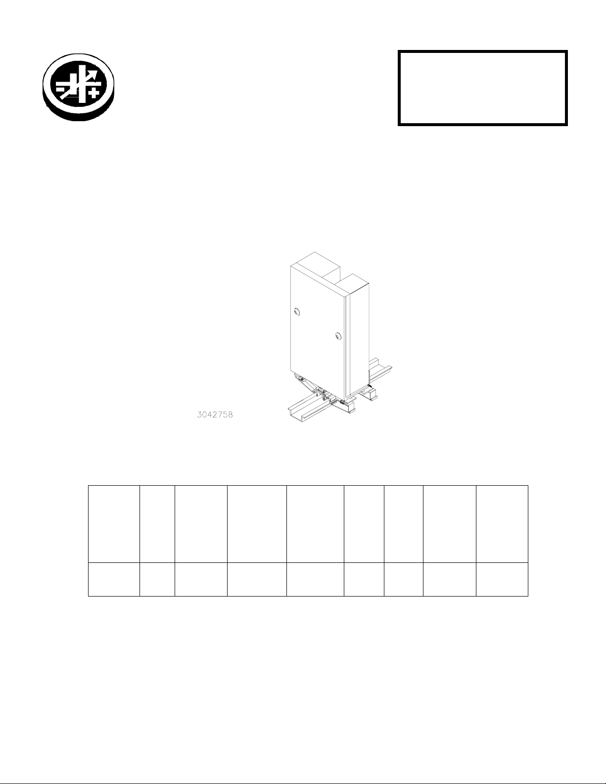
DESCRIPTION. Kepco KIT, Models DIN KRW-P contains a cover, a cable kit, a mounting bracket with left and right
preassembled mounting clips and associated hardware used to install KRW 350KV (+5V, ±12V) and KRW 351KV
(+5V, ±15V) power supplies on a DIN rail. The “P” suffix is for mounting the power supply perpendicular to the DIN rail
as shown in Figure 1. Outline Dimensions are shown in Figure 5
FIGURE 1. P SUFFIX ORIENTATION
TABLE 1. COMPONENTS SUPPLIED
SCREW
CABLE
KIT
PART
NO.
219-0242 CA 29 128-2058
KEPCO, INC. " 131-38 SANFORD AVENUE " FLUSHING, NY. 11352 U.S.A. " TEL (718) 461-7000 "
©2004, KEPCO, INC
Data subject to change without notice 228-1484
COVER
PART
NO.
MOUNTING
BRACKET
PART NO.
http://www.kepcopower.com " email: hq@kepcopower.com
(QTY 2)
(Power Supply
To Mounting
Bracket)
PART NO.
101-0383
(8-32 X 3/16
PHPH)
WAS HE R
(QTY 2)
(Power Supply
To Mounting
Bracket)
PART NO.
103-0017
(NO. 8, INT.
TOOTH)
CLIP
(QTY 2)
PART
NO.
108-0366 128-1971
CLIP
PLATE
(QTY 2)
PART
NO.
SCREW
Thread-form
(QTY 4)
(Clip To
Mounting
Bracket)
PART NO.
101-0443
(4-40 X 1/4
BHPH)
FAX (718) 767-1102
WAS HE R
(QTY 4)
(Clip To
Mounting
Bracket)
PART NO.
103-0014
(NO. 4, INT.
TOOTH)
1
Page 2
INSTALLATION
1. INSTALL COVER. Attach the cover to the power supply per instruction manual supplied with the cover.
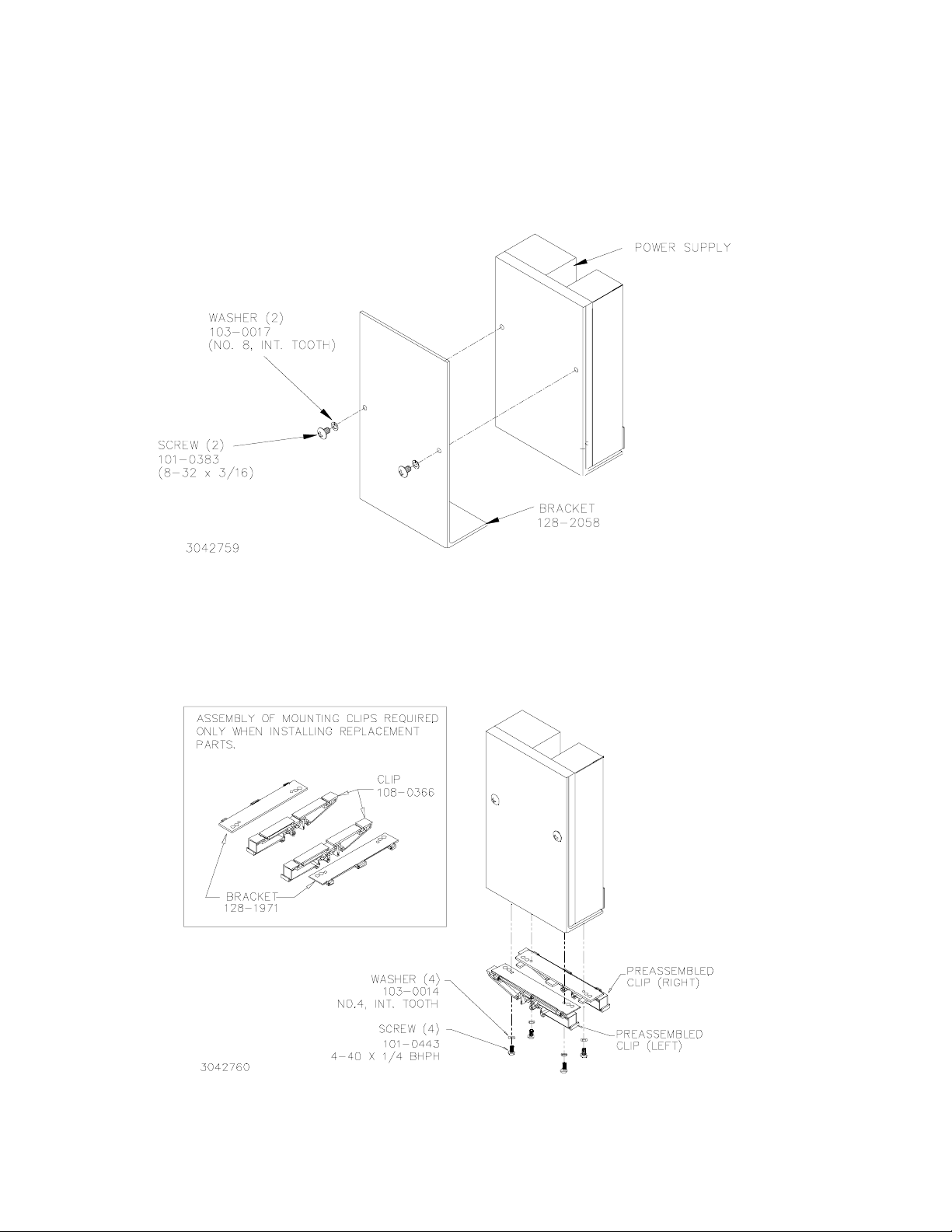
2. INSTALL MOUNTING BRACKET. Attach the mounting bracket to the power supply using the hardware
supplied (see Figure 2).
FIGURE 2. INSTALLING MOUNTING BRACKET ON POWER SUPPLY
3. INSTALL CLIPS. Attach preassembled mounting clips into the mounting bracket holes using hardware
supplied (see Figure 3).
FIGURE 3. INSTALLING CLIPS ON MOUNTING BRACKET
KEPCO, INC. " 131-38 SANFORD AVENUE " FLUSHING, NY. 11352 U.S.A. " TEL (718) 461-7000 "
http://www.kepcopower.com " email: hq@kepcopower.com
2
FAX (718) 767-1102
228-1484 022504
Page 3

4. INSTALL CABLE KIT. Attach wires to the power supply per Instruction Sheet supplied with cable kit.
5. INSTALL POWER SUPPLY ON DIN RAIL. To mount the power supply on the rail insert one end of both
mounting clips under one edge of the rail, then snap the other end of the two clips into place (see Figure 4A).
INSTALLATION
A
B
REMOVAL
FIGURE 4. INSTALLATION AND REMOVAL OF POWER SUPPLY FROM DIN RAIL
REMOVING POWER SUPPLY FROM DIN RAIL. While grasping the power supply with one hand, Insert a screw-
driver into the access holes provided and apply leverage towards the left as shown in Figure 4B to disengage each clip
from the rail. Where mounting clips are close together, it may be necessary to apply leverage with two screwdrivers
simultaneously.
KEPCO, INC. " 131-38 SANFORD AVENUE " FLUSHING, NY. 11352 U.S.A. " TEL (718) 461-7000 "
http://www.kepcopower.com " email: hq@kepcopower.com
022504 228-1484
FAX (718) 767-1102
3
Page 4

FIGURE 5. MRW 35W/50W/65W POWER SUPPLY WITH KIT INSTALLED, OUTLINE DIMENSIONS
KEPCO, INC. " 131-38 SANFORD AVENUE " FLUSHING, NY. 11352 U.S.A. " TEL (718) 461-7000 "
http://www.kepcopower.com " email: hq@kepcopower.com
4
FAX (718) 767-1102
228-1484 022504
 Loading...