

Page 1
INSTRUCTION SHEET
KEPCO
An ISO 9001 Company.
CABLE
KIT
219-0445
CABLE KIT NO. 219-0445
BOP 1000W MODELS (2) IN PARALLEL
I.
DESCRIPTION.
This kit contains the three cables, Power Output, Bitbus and Master/Slave Control, required to operate
two 1000 Watt BOP High Power models in parallel, effectively doubling the output current capacity.
Only two identical models may be configured to operate in parallel. Table 1 lists the equipment supplies
in this Kit.
TABLE 1. EQUIPMENT SUPPLIED
Item Purpose Kepco Part Number
Connects the power output terminals of the slave unit (OUT
Power Output Cable
Master/Slave
Control Cable
and COMMON) to the corresponding power output terminals
of the master.
Connects the slave control ports of the master and slave for
parallel operation.
118-1112
118-1107
Bitbus Cable Allows communication between Master and Slave via Bitbus 118-1108
Instruction Manual
This manual is arranged as follows:
• Section I lists the equipment supplied.
• Section II explains how to install the cables and configure the two units to operate in parallel,
including initial calibration.
• Section III describes how to calibrate a previously installed parallel configuration.
• Section IV lists the specifications for the parallel combination.
• Section V provides special operating instructions for the parallel combination.
II.
INSTALLATION.
Provides installation and operation instructions for operating
two 1000W BOP models in Parallel
WARNING
BE SURE ALL POWER IS DISCONNECTED FROM
POWER SUPPLIES BEFORE INSTALLING CABLES
228-1472
KEPCO, INC. " 131-38 SANFORD AVENUE " FLUSHING, NY. 11352 U.S.A. " TEL (718) 461-7000 " FAX (718) 767-1102
©2003, KEPCO, INC
Data subject to change without notice
http://www.kepcopower.com "
228-1472 REV 3 091903
email: hq@kepcopower.com
Page 2

NOTE: The following procedure assumes that both individual units are properly calibrated. If not, refer
to the associated technical manuals to calibrate the individual units prior to connecting them
as a parallel pair. Perform all calibration steps for both master and slave unit.
1. Before powering up the parallel combination, connect the Power Output, Bitbus, and Master/
Slave Control cables (supplied) to the master and slave units in parallel star type configuration
(load connected to the master output) as shown in Figure 1 for local sensing or Figure 2 for
remote sensing. Always remove link between COM and COM S terminals for the slave. For a
master configured for remote sensing, remove both links between OUT and OUT S and between
COM and COM S terminals.
CAUTION:The connectors of the Master/slave Control cable are marked Master and Slave.
Make sure these are installed properly. Installing the cable backwards (cable connector marked MASTER installed in a slave, cable connector marked SLAVE
installed in a master) can cause irreparable damage.
NOTE: To power down the combination, first press the STANDBY key on the master to disable the
output, then turn off the slave followed by the master.
2. To configure the unit to be designated as a slave proceed as follows:
a. Turn on power only to the unit to be designated as a slave.
b. From the main screen (power on default), press
to enter the Settings Menu.
%
c. From the Settings menu, gain access to the Protected Settings menu by first entering the
password. Scroll through the password characters using
to select the character position, then press ENTER. The status message changes to
tected settings enabled
ter and
d. Press
or ADJUST control to fix it, or press CLEAR to start over.)
U
to enter the Protected Settings Menu.
$
e. From the Protected Settings menu, highlight
keys) and press ! to modify. Highlight
U
f. From the Protected Settings menu, under
modify. Highlight
Parallel
. (If unsuccessful, use T or R to highlight the incorrect charac-
Unit Type
SLAVE #1
Unit Type
and press ! apply the change.
and press ! to apply the change.
g. Exit the Protected Settings menu and return to main screen by pressing
tings upon power-up. The unit goes to REMOTE mode, the status message reads
Module not found
, the Fault indicator is lit, and the unit continues to beep once a minute
until the master is found. The only function key displayed is
or ADJUST control and T or
U
(use ADJUST control or the Y or
highlight
Expansion
- LOCAL.
!
and press ! to
to save the set-
$
MASTER
R
Pro-
CAUTION: The unit has now been properly configured as a slave to be controlled only by the
master. Do not use the slave keypad, RS 232 port or GPIB port to try to control the
slave.
KEPCO, INC. " 131-38 SANFORD AVENUE " FLUSHING, NY. 11352 U.S.A. " TEL (718) 461-7000
FAX (718) 767-1102 " email: kepcopower@aol.com
2
228-1472 REV 3 091903
Page 3
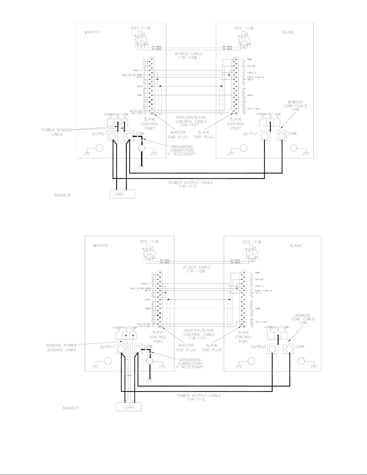
FIGURE 1. INTERCONNECTIONS FOR PARALLEL OPERATION OF TWO (2) BOP HIGH
POWER MODELS USING LOCAL SENSING
FIGURE 2. INTERCONNECTIONS FOR PARALLEL OPERATION OF TWO (2) BOP HIGH
POWER MODELS USING REMOTE SENSING
KEPCO, INC. " 131-38 SANFORD AVENUE " FLUSHING, NY. 11352 U.S.A. " TEL (718) 461-7000
FAX (718) 767-1102 " email: kepcopower@aol.com
091903 228-1472 REV 3
3
Page 4
3. Turn on the unit to be configured as a master and note that upon power up the FAULT light will go
on (this is normal). Proceed as follows:
a. From the main screen, press
to enter the Settings Menu.
%
b. From the Settings menu, gain access to the Protected Settings menu by first entering the
password (see Step 2c above).
c. From the Protected Settings menu, highlight
keys) and press ! to modify. Highlight
d. From the Protected Settings menu, under
modify. Highlight
Parallel
and press ! to apply the change.
e. Exit the Protected Settings menu by pressing
Unit Type
Master +1
Unit Type
to test the system and to save the settings
$
(use ADJUST control or Y or
and press ! to apply the change.
highlight
Expansion
and press ! to
U
for subsequent power-up cycles. The display shows the master power-up screen (see Figure 3).
NOTE: Pressing
to exit will cause the unit to revert to a standalone unit.
%
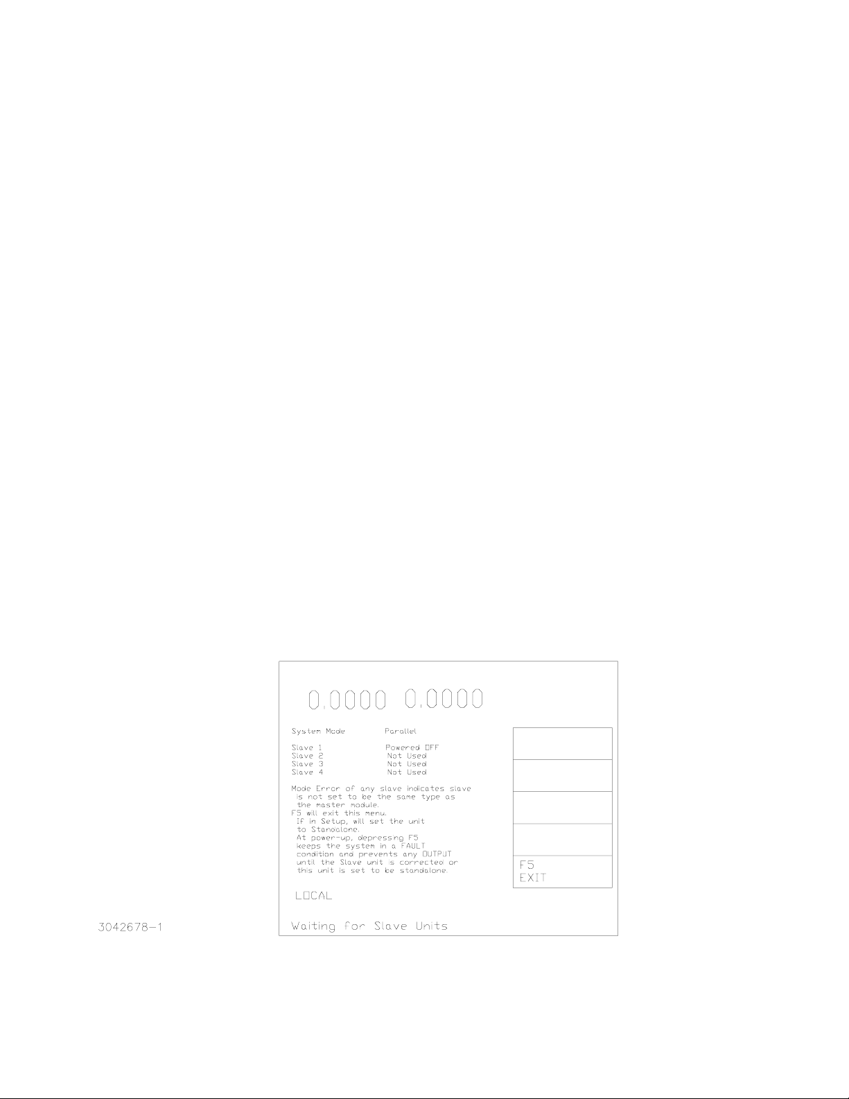
f. The power-up master module screen (Figure 3) changes to show the status of Slave 1 (see
Table 2).
If the slave is recognized as ready, after about 10 seconds the master LCD reverts to the
Power On Default screen (see Figure 4). The slave also displays the Power On Default
screen (see Figure 5), except the unit will be in Current Mode, no function keys are active
and the Status message at the bottom is
KPAD Locked
, indicating the keypad is disabled.
The fault indicators on both units are off.
If the master power-up screen is still displayed after 10 seconds, the slave was not properly
recognized. Pressing
or turning power off, then on again, reconfigures the unit as a stan-
%
dalone unit. Verify that the BITBUS cable is installed correctly. Verify that the slave has
been properly configured as a slave per step 2 above. Repeat step 3. If the power up
screen still does not revert to the power on default screen, refer to troubleshooting.
VOLTAGE
CURRENT
VOLTAGE
SOURCE
CPROTECT
FIGURE 3. MASTER POWER UP SCREEN
KEPCO, INC. " 131-38 SANFORD AVENUE " FLUSHING, NY. 11352 U.S.A. " TEL (718) 461-7000
FAX (718) 767-1102 " email: kepcopower@aol.com
4
228-1472 REV 3 091903
Page 5

VOLTAGE
SOURCE
VO LTA G E
0.
0000
FIGURE 4. POWER ON DEFAULT SCREEN FOR MASTER UNIT
VOLTAGE
SOURCE
FIGURE 5. POWER ON DEFAULT SCREEN FOR SLAVE UNIT
TABLE 2. SLAVE STATUS MESSAGE DEFINITIONS (DISPLAYED ON MASTER POWER UP SCREEN)
DISPLAYED STATUS
(see Figure 3, SLAVE 1)
Ready Unit is ready for operation.
STANDBY Unit’s FAULT indicator is on.
Powered OFF Unit is not responding to polls via BITBUS.
Failed Unit’s FAULT indicator is on, and hardware error has been detected.
Not Used Unit is not part of parallel configuration
Unknown Waiting for interface communication
4. At the master unit calibrate the parallel combination as follows:
a. From the main screen, press
KEPCO, INC. " 131-38 SANFORD AVENUE " FLUSHING, NY. 11352 U.S.A. " TEL (718) 461-7000
FAX (718) 767-1102 " email: kepcopower@aol.com
091903 228-1472 REV 3
to enter the Settings Menu.
%
MEANING
5
Page 6

b. From the Settings menu, gain access to the Protected Settings menu by first entering the
password (see step 2c above).
c. Press
Calibration Multiple Units
Connect a short across Master Power Output.
Depress any Key to continue.
from the Protected Settings menu to begin Calibration. The LCD shows
@
After connecting a short across output terminals of master, depress any key on the keypad.
VOLTAGE
CURRENT
VOLTAGE
SOURCE
FIGURE 6. CALIBRATION SCREEN
d. Press # from the main calibration menu to select Multiple. The Calibration Screen (Figure
6) is displayed. The status of the process is updated as calibration proceeds (this may take
approximately three minutes). The Current State is updated from zero to maximum and
minimum as the current calibration proceeds (voltage calibration is not required for the parallel pair).
e. When the calibration is complete the LCD displays
PLEASE REMOVE SHORT FROM
OUTPUTS OF POWER SUPPLIES
Depress Any Key to continue.
After removing the short, depress any key on the keypad.
f. When prompted, enter the calibration date (8 characters maximum, any format) using
ADJUST control to scroll through the characters and
or R to select the character posi-
T
U
tion, then press ENTER.
g. Exit the Calibration menu by pressing
to save the settings upon power-up.
$
5. Adjust the limits to reflect the increased current capacity of the parallel combination as follows:
or
KEPCO, INC. " 131-38 SANFORD AVENUE " FLUSHING, NY. 11352 U.S.A. " TEL (718) 461-7000
FAX (718) 767-1102 " email: kepcopower@aol.com
6
228-1472 REV 3 091903
Page 7

a. From the main screen, press % to enter the Settings Menu.
b. From the Settings menu, press
@ to enter the Modify Limits menu. Press @ to restore defaults. The
values for +Current Max, –Current Min and ±Current Protect Max/Min should now be for the parallel
combination.
c. Exit the Modify Limits menu by pressing
$ to save the settings upon power-up.
6. Verify that the output is zero and remove the short across the output of the parallel configuration.
NOTE: Changing the password of the parallel pair (i. e., the master) does not change the password of the slave
unit. It is recommended that the slave unit password be recorded and be readily accessible when calibration of the slave unit is required.
III.
CALIBRATING AN EXISTING PARALLEL CONFIGURATION
If the individual units of a parallel comb7ination need to be calibrated proceed as follows:
1. Power down the combination: first press the STANDBY key on the master to disable the output, then turn off
the slave, followed by the master.
2. Disconnect the master/slave cable connections.
3. Turn on power to both units in any order.
4. The slave unit will power up in
REMOTE
and will display
LOCAL LOCKOUT
. To restore LOCAL control, press
to set the unit to LOCAL mode.
!
5. If calibration is to be done via the front panel keypad, refer to the front panel calibration procedure in the
associated technical manual and calibrate both units. If the calibration is to done via the GPIB (using either
SCPI commands or the soft panel) both master and slave units must be temporarily reconfigured as standalone units:
a. From the main screen (power on default), press
to enter the Settings Menu.
%
b. From the Settings menu, gain access to the Protected Settings menu by first entering the password
(see PAR. II, step 2c).
c. From the Protected Settings menu, highlight UNIT TYPE (use ADJUST control or arrow keys) and
press
d. From the Protected Settings menu, highlight MULTIPLE UNITS and press
NONE and press
e. Exit the Protected Settings menu and return to main screen by pressing
to modify. Highlight STANDALONE and press ! to apply the change.
!
to apply the change.
!
%
to modify. Highlight
!
.
f. Calibrate the master and slave units by referring to the applicable calibration procedure in the associ-
ated technical manual.
g. Turn off power to both units (since step e exited without saving the settings, this restores the previous
master/slave settings).
6. Refer to Figure 1 for local sensing or Figure 2 for remote sensing and connect the master and slave units in
parallel star type configuration (load connected to master) using the Master/slave Control, Power Output
and Bitbus cables.
KEPCO, INC. " 131-38 SANFORD AVENUE " FLUSHING, NY. 11352 U.S.A. " TEL (718) 461-7000
FAX (718) 767-1102 " email: kepcopower@aol.com
091903 228-1472 REV 3
7
Page 8

7. Verify the master unit is in STANDBY, then connect a short across the output of the parallel configuration (see Figure 1 or Figure 2).
8. At the master unit calibrate the parallel combination as follows:
a. From the main screen, press
to enter the Settings Menu.
%
b. From the Settings menu, gain access to the Protected Settings menu by first entering the
password (see step 2c above).
c. Press
d. Press
from the Protected Settings menu to begin Calibration.
@
from the main calibration menu to select Multiple. Monitor the LCD to see the sta-
#
tus while calibration of the parallel configuration proceeds automatically (this may take
approximately 3 minutes).
e. When the calibration is complete, the LCD will display
PUTS OF POWER SUPPLIES Depress Any Key to continue.
PLEASE REMOVE SHORT FROM OUT-
f. When prompted, enter the calibration date using U or ADJUST control to scroll through the
characters and
g. Exit the Calibration menu by pressing
or R to select the character position, then press ENTER.
T
to save the settings upon power-up.
$
9. Remove the short across the output of the parallel configuration.
IV.
SPECIFICATIONS
Table 3 lists the model parameters unique to a parallel combination of two 1000W BOP Power Supplies.
Table 4 lists the general specifications applicable all the parallel combinations listed in Table 3.
TABLE 3. MODEL PARAMETERS FOR TWO (2) HIGH POWER BOP 1000 WATT UNITS (PARALLEL)
d-c Output Range Closed Loop Gain
Model
TWO 1000 WATT MODELS
BOP 10-75MG ±10V d-c ±150A d-c 1.0 15.0
BOP 20-50MG ±20V d-c ±100A d-c 2.0 10.0
BOP 36-28MG ±36V d-c ±56A d-c 3.6 5.5
BOP 50-20MG ±50V d-c ±40A d-c 5.0 4.0
BOP 72-14MG ±72V d-c ±28A d-c 7.2 2.8
BOP 100-10MG ±100V d-c ±20A d-c 10.0 2.0
KEPCO, INC. " 131-38 SANFORD AVENUE " FLUSHING, NY. 11352 U.S.A. " TEL (718) 461-7000
FAX (718) 767-1102 " email: kepcopower@aol.com
E
O Max
8
I
O Max
228-1472 REV 3 091903
Vol ta ge
Channel
Current
Channel
Page 9

TABLE 4. GENERAL SPECIFICATIONS FOR TWO (2) HIGH POWER 1000W BOP UNITS
CONNECTED IN PARALLEL
SPECIFICATION RATING/DESCRIPTION
CONDITION
INPUT CHARACTERISTICS
a-c voltage nominal 230 Va-c
range 176 - 264 Va-c
Frequency nominal 50-60 Hz
range 47 - 65 Hz
Current 176 Va-c 19A maximum
264 Va-c 13A maximum
Power factor
Efficiency 65% minimum
Switching frequency 80 KHz PFC Stage
EMC Compliance EN61326-1 (1997) Class A equipment
EMC immunity to: ESD EN61000-4-2 Electrostatic discharge
EMC emissions Conducted EN61000-3-2 harmonics
Leakage current 3.5 mA 230V a-c 47-63 Hz
Insulation coordination Input Installation Category II
Pollution degree 2
Source 0.99 minimum
Sink 0.97 minimum
Radiated RF EN61000-4-3
EFT EN61000-4-4 Electrical fast transient/burst
Surges EN61000-4-5
Conducted RF EN61000-4-6
EN61000-3-3 fluctuation & flicker
Conducted EN55011/CISPR11 0.15 to 30 MHz
Radiated EN55011/CISPR11 30 to 1000 MHz
Overvoltage Category II
Output Installation Category II
Overvoltage Category II
Single phase
>65 Hz, leakage
exceeds spec
nominal output power
OUTPUT CHARACTERISTICS
Type of stabilizer Voltage-current, 4-quadrant Switch mode
Switching frequency 100KHz Output Stage
Source adjustment
range
Sink adjustment range voltage -100% to +100% of rating
Programming
resolution / accuracy
Readback
resolution / accuracy
Readback
rate/array
measurement rate 1 ms (default) range: 0.25-25ms
measurement array 64 samples
voltage -100% to +100% of rating
current -100% to +100% of rating
Recuperated energy is sent back into
current -100% to +100% of rating
Voltage 14 bits / 0.2%
Current 14 bits / 0.5%
Limits 12 bits / 0.5% voltage or current
Voltage 16 bits / 0.2% main or limit channel
Current 16 bits / 0.5% main or limit channel
0 to 50 deg C
line for reuse
KEPCO, INC. " 131-38 SANFORD AVENUE " FLUSHING, NY. 11352 U.S.A. " TEL (718) 461-7000
FAX (718) 767-1102 " email: kepcopower@aol.com
091903 228-1472 REV 3
9
Page 10

TABLE 4. GENERAL SPECIFICATIONS FOR TWO (2) HIGH POWER 1000W BOP (CONTIN-
UED)UNITS CONNECTED IN PARALLEL
SPECIFICATION RATING/DESCRIPTION
CONDITION
OUTPUT CHARACTERISTICS (Continued)
Voltage stabilization in
voltage mode
Current stabilization in
current mode
Error sensing 0.25V per wire Above rated output
Transient recovery in
voltage mode
Isolation voltage 300V Output to ground
Output limiting voltage and current limited in four quadrants
Output Stage Protection
Input Stage Protection (PFC)
source effect 0.05% of rating min-max input voltage
load effect 0.1% of rating 0-100% load current
time effect (drift) 0.05% of rating 0.5 through 24 hours
temperature 0.05%/deg C of rating 0 to 50 deg C
ripple and noise 2% E0max p-p Includes switching noise
source effect 0.05% of rating min-max input voltage
load effect 0.2% of rating 0-100% load voltage
temperature 0.05%/deg C of rating 0 to 50 deg C
ripple and noise 2% I0max p-p Includes switching noise
maximum excursion 5% of nominal output nominal voltage, 50% load step
Recovery time 200
Heatsink overtemperature,
switchers overcurrent for master
Overvoltage, undervoltage, overcurrent,
heat sink overtemperature, fan inopera-
tive for master and slave units
Circuit breaker overcurrent
µ
sec Return within 0.1% of set voltage
and slave units
Triggers latched shutdown protection of
entire master/slave combination
Triggers latched shutdown protection of
entire master/slave combination
Trips circuit breaker to shut off unit
(master or slave)
PROGRAMMING/DISPLAY CHARACTERISTICS
Small signal Bandwidth voltage channel 2 KHz minimum into nominal resistive load, 10% of rating
current channel 400 Hz minimum Into short circuit, 10% of rating
µ
Rise/Fall Time voltage channel 500/200
current channel 1.5/2.5 msec
Analog control voltage channel –10V to +10V
current channel –10V to +10V
Digital control local Panel-mounted keypad Direct Entry
remote IEEE 488-2 (GPIB)
remote RS 232
remote RS 485 (BITBUS) IEEE 1118
Display front panel 4" backlit LCD displays all functions
remote All parameters read back on GPIB or RS 232 buses
sec
into nominal resistive load, 10-90%,
0 to ±100% of rating
into short circuit, 10-90%,
0 to ±100% of rating
Full range output,
10K Ohm input impedance
SCPI
10
KEPCO, INC. " 131-38 SANFORD AVENUE " FLUSHING, NY. 11352 U.S.A. " TEL (718) 461-7000
FAX (718) 767-1102 " email: kepcopower@aol.com
228-1472 REV 3 091903
Page 11

TABLE 4. GENERAL SPECIFICATIONS FOR TWO (2) HIGH POWER 1000W BOP (CONTIN-
UED)UNITS CONNECTED IN PARALLEL
SPECIFICATION RATING/DESCRIPTION
CONDITION
BOP HIGH POWER INTERFACE CHARACTERISTICS
Waveform Support steps 1002
µ
step dwell time 250
Storage non-volatile FLASH-type EEPROM 24Kbytes
** User setups 99
interface steps 99
** waveform display 1024 steps
** waveform - interface 1800 steps
sec to 10 sec
GENERAL (ENVIRONMENTAL) CHARACTERISTICS
Temperature operating 0 to +50 deg C Full rated load
storage -20 to +85 deg C
Cooling Two internal fans per unit exhaust to the rear
Humidity 0 to 95% RH non-condensing
Shock 20g. 11msec ±50% half sine non-operating
Vibration 5-10HZ: 10mm double amplitude 3 axes, non-operating
10-55HZ: 2g 3 axes, non-operating
Altitude sea level to 10,000 feet
Safety Certification a-c power UL 3101-1 and EN 6101-1 Pending
** Optional Function. if you require an option that is not installed on your unit, please contact the factory for upgrade information.
V.
OTHER CONSIDERATIONS
When operating two units in parallel the following information supplements the Power Supply technical
manual.
1. Apply power to the combination by first turning on the master, then turn on the slave. If the master
is in STANDBY, depress the STANDBY key on the master to apply power to the output terminals.
(To power down the combination, first press the STANDBY key on the master to disable the output, then turn off the slave, followed by the master.
2. When the units of a parallel configuration are first turned on there is a brief delay until both units
are communicating over the BITBUS to form the parallel pair.
When the master is turned on, the unit initially displays the Power Up Status and Test screen (Figure 7), then displays the Master Power Up screen (Figure 3). As the master searches for slaves.
When the slave is turned on, the unit initially displays the Power Up Status and Test screen (Figure 7), then automatically goes to REMOTE mode. The status message reads
not found
is found. The only function key displayed is
, the Fault indicator is lit, and the unit continues to beep once a minute until the master
- LOCAL.
!
MASTER Module
When the master finally recognizes the slave, the master LCD reverts to the Power On Default
screen (see Figure 3). The slave displays the Power On Default screen (see Figure 3), except the
unit will be in Current Mode, no function keys are active and the Status message at the bottom is
KPAD Locked
, indicating the keypad is disabled. The fault indicators on both units are off.
KEPCO, INC. " 131-38 SANFORD AVENUE " FLUSHING, NY. 11352 U.S.A. " TEL (718) 461-7000
FAX (718) 767-1102 " email: kepcopower@aol.com
091903 228-1472 REV 3
11
Page 12

3. Operation of the parallel combination is done by operating the master as described for a single
unit in the High Power BOP Technical Manual. SCPI commands and front panel controls actions
applied to the master affect the parallel combination. The LCD display of the master refers to the
parallel combination, while the front panel LCD of the slave shows the actual voltage and current
provided by the slave.
FIGURE 7. POWER UP STATUS AND TEST SCREEN
12
KEPCO, INC. " 131-38 SANFORD AVENUE " FLUSHING, NY. 11352 U.S.A. " TEL (718) 461-7000
FAX (718) 767-1102 " email: kepcopower@aol.com
228-1472 REV 3 091903
 Loading...