

Page 1
QUICK START GUIDE
KEPCO
An ISO 9001 Company.
BOP 1KW-GL POWER SUPPLY
This guide gives a brief introduction to the BOP 1KWGL Power supply, shows simple load connections, and
allows you to verify the power supply is working. The
guide also shows you how to perform the most commonly used functions.
ACCESSING MANUALS. First determine your
Firmware Version (see below), then download the BOP
1KW-GL Operator’s Manual from
www.kepcopower.com/support/opmanls.htm#bop-gl
Refer to the BOP 1KW-GL Operator’s Manual for full
specifications, installation considerations and operating instructions. The BOP 1KW-GL Operator’s
Manual also includes a full description of the digital
interfaces and the SCPI command language.
BOP
1KW-GL
FIRMWARE VERSION. With no load connected
and power off, use either the GPIB port or RS 232
port (see page 6) to accept remote commands.
If necessary, refer to “Reset Power-up” on page 8
and Figure 5 to configure the GPIB address (default
is 6) or configure the RS 232 baud rate (default is
9600).
Apply power to the unit and send *IDN? query. The
unit responds with a character string containing the
following fields: <Manufacturer>,<Model VoltageCurrent Calibration Date>,<Serial Number>, <Firmware Version> e.g., KEPCO, BOP1KW 20-50 09/30/
2001,123456,4.01.
ACCESSING DRIVERS. Drivers are accessed
from www.kepcopower.com/drivers/drivers-dl3.htm.
CONTENTS
Description . . . . . . . . . . . . . . . . . . . . . . . . . . . . . . . . . . . . . . . . . . . . . . . . . . . . . . . . . . . . . . . . . . . . . . . . . . . . . . . . . . . . . . . . . . 2
Unpacking . . . . . . . . . . . . . . . . . . . . . . . . . . . . . . . . . . . . . . . . . . . . . . . . . . . . . . . . . . . . . . . . . . . . . . . . . . . . . . . . . . . . . . . . . . 2
Equipment Supplied . . . . . . . . . . . . . . . . . . . . . . . . . . . . . . . . . . . . . . . . . . . . . . . . . . . . . . . . . . . . . . . . . . . . . . . . . . . . . . . . . . 2
Accessories . . . . . . . . . . . . . . . . . . . . . . . . . . . . . . . . . . . . . . . . . . . . . . . . . . . . . . . . . . . . . . . . . . . . . . . . . . . . . . . . . . . . . . . . . 4
Safety . . . . . . . . . . . . . . . . . . . . . . . . . . . . . . . . . . . . . . . . . . . . . . . . . . . . . . . . . . . . . . . . . . . . . . . . . . . . . . . . . . . . . . . . . . . . . 4
Preliminary Operational Check . . . . . . . . . . . . . . . . . . . . . . . . . . . . . . . . . . . . . . . . . . . . . . . . . . . . . . . . . . . . . . . . . . . . . . . . . . 5
Installation . . . . . . . . . . . . . . . . . . . . . . . . . . . . . . . . . . . . . . . . . . . . . . . . . . . . . . . . . . . . . . . . . . . . . . . . . . . . . . . . . . . . . . . . . . 5
Input Connections. . . . . . . . . . . . . . . . . . . . . . . . . . . . . . . . . . . . . . . . . . . . . . . . . . . . . . . . . . . . . . . . . . . . . . . . . . . . . . . . 5
Load Connections. . . . . . . . . . . . . . . . . . . . . . . . . . . . . . . . . . . . . . . . . . . . . . . . . . . . . . . . . . . . . . . . . . . . . . . . . . . . . . . . 5
Local Sensing (Factory Default). . . . . . . . . . . . . . . . . . . . . . . . . . . . . . . . . . . . . . . . . . . . . . . . . . . . . . . . . . . . . . . . . . . . . . 6
Remote Sensing Select. . . . . . . . . . . . . . . . . . . . . . . . . . . . . . . . . . . . . . . . . . . . . . . . . . . . . . . . . . . . . . . . . . . . . . . . . . . . 6
Analog I/O Connections. . . . . . . . . . . . . . . . . . . . . . . . . . . . . . . . . . . . . . . . . . . . . . . . . . . . . . . . . . . . . . . . . . . . . . . . . . . . 6
Trigger Connections. . . . . . . . . . . . . . . . . . . . . . . . . . . . . . . . . . . . . . . . . . . . . . . . . . . . . . . . . . . . . . . . . . . . . . . . . . . . . . . 6
GPIB Connections. . . . . . . . . . . . . . . . . . . . . . . . . . . . . . . . . . . . . . . . . . . . . . . . . . . . . . . . . . . . . . . . . . . . . . . . . . . . . . . . 6
RS 232 Connections. . . . . . . . . . . . . . . . . . . . . . . . . . . . . . . . . . . . . . . . . . . . . . . . . . . . . . . . . . . . . . . . . . . . . . . . . . . . . . 6
Operation . . . . . . . . . . . . . . . . . . . . . . . . . . . . . . . . . . . . . . . . . . . . . . . . . . . . . . . . . . . . . . . . . . . . . . . . . . . . . . . . . . . . . . . . . . . 8
Power-up Settings . . . . . . . . . . . . . . . . . . . . . . . . . . . . . . . . . . . . . . . . . . . . . . . . . . . . . . . . . . . . . . . . . . . . . . . . . . . . . . . . 8
Turning The Power Supply On. . . . . . . . . . . . . . . . . . . . . . . . . . . . . . . . . . . . . . . . . . . . . . . . . . . . . . . . . . . . . . . . . . . . . . . 8
Reset Power-up . . . . . . . . . . . . . . . . . . . . . . . . . . . . . . . . . . . . . . . . . . . . . . . . . . . . . . . . . . . . . . . . . . . . . . . . . . . . . . 8
Normal Power-up . . . . . . . . . . . . . . . . . . . . . . . . . . . . . . . . . . . . . . . . . . . . . . . . . . . . . . . . . . . . . . . . . . . . . . . . . . . . . 9
Power Supply Basics. . . . . . . . . . . . . . . . . . . . . . . . . . . . . . . . . . . . . . . . . . . . . . . . . . . . . . . . . . . . . . . . . . . . . . . . . . . . . . 9
Voltage and Current Parameters. . . . . . . . . . . . . . . . . . . . . . . . . . . . . . . . . . . . . . . . . . . . . . . . . . . . . . . . . . . . . . . . . . . . . 9
Setting Voltage or Current Mode. . . . . . . . . . . . . . . . . . . . . . . . . . . . . . . . . . . . . . . . . . . . . . . . . . . . . . . . . . . . . . . . . . . . . 9
Voltage/Current Protect Limits (Limit Channel Software Limits). . . . . . . . . . . . . . . . . . . . . . . . . . . . . . . . . . . . . . . . . . . . 11
Software Limits. . . . . . . . . . . . . . . . . . . . . . . . . . . . . . . . . . . . . . . . . . . . . . . . . . . . . . . . . . . . . . . . . . . . . . . . . . . . . . . . . 11
Maximum/Minimum Protection Limits (Software-controlled). . . . . . . . . . . . . . . . . . . . . . . . . . . . . . . . . . . . . . . . . . . . . . . 11
Determining How the Unit Responds when Output is OFF (Load Type). . . . . . . . . . . . . . . . . . . . . . . . . . . . . . . . . . . . . . 11
Configure Load Type. . . . . . . . . . . . . . . . . . . . . . . . . . . . . . . . . . . . . . . . . . . . . . . . . . . . . . . . . . . . . . . . . . . . . . . . . . . . . 13
Enabling/disabling Output Power. . . . . . . . . . . . . . . . . . . . . . . . . . . . . . . . . . . . . . . . . . . . . . . . . . . . . . . . . . . . . . . . . . . . 13
Additional Features . . . . . . . . . . . . . . . . . . . . . . . . . . . . . . . . . . . . . . . . . . . . . . . . . . . . . . . . . . . . . . . . . . . . . . . . . . . . . . . . . . 13
KEPCO, INC. 131-38 SANFORD AVENUE FLUSHING, NY. 11355 U.S.A. TEL (718) 461-7000 FAX (718) 767-1102
093013 228-1699 REV 2 1
http://www.kepcopower.com email: hq@kepcopower.com
Page 2
I — DESCRIPTION
The BOP 1KW-GL Series hereafter referred to as
BOP-GL, are true 4-quadrant programmable voltage
and current power supplies, meaning they are capable of both sourcing and sinking power (see Figure
1).
The BOP-GL models have been optimized for
exceptionally low current ripple and noise and
improved stability (drift and temperature), making
them ideal for driving inductive loads such as large
magnets or motors. These bipolar power supplies
pass smoothly through zero without switching to provide true ± voltage and ± current. These BOP-GL
power supplies use switch mode technology for low
dissipation. A bi-directional, isolating, a-c input
power factor correcting (PFC) circuit recuperates
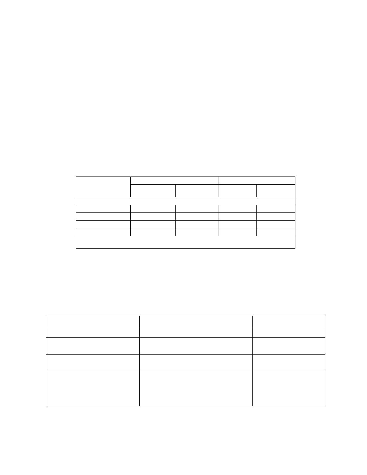
TABLE 1. BOP-GL 1000 WATT MODEL PARAMETERS
d-c Output Range Closed Loop Gain
Model
1000 WATT MODELS
BOP 10-100GL ±10V d-c ±100A d-c 1.0 10.0
BOP 20-50GL ±20V d-c ±50A d-c 2.0 5.0
BOP 36-28GL ±36V d-c ±28A d-c 3.6 2.8
BOP 50-20GL ±50V d-c ±20A d-c 5.0 2.0
NOTE: When connecting active loads, the steady-state voltage of the active load must not exceed the maximum
voltage rating of the BOP. Otherwise the overvoltage protection will shut down the power supply.
E
O Max
energy sinked from an active load and sends it back
into the line to maintain low dissipation.
These BOP power supplies can be controlled
remotely by an analog ±10V input for the main channel (voltage or current), and by a +1 to +10V input
for the limit channels. They can also be controlled
through one of the standard digital interfaces (GPIB
or RS 232) to set voltage and current and the four
protection limits (+voltage, –voltage, +current and –
current.) Output voltage and current can be remotely
monitored via the analog monitor signals present at
the rear panel Analog I/O Port connector, or by using
SCPI commands via either the RS 232 or GPIB
ports.
.
I
O Max
Vol tag e
Channel
Current
Channel
II — UNPACKING
This instrument has been thoroughly inspected and
tested prior to packing and is ready for operation.
After careful unpacking, inspect for shipping damage
before attempting to operate. Perform the “Preliminary Operational Check” on page 5. If any indication
TABLE 2. EQUIPMENT SUPPLIED
ITEM FUNCTION
Source Power Entry mating connector Mates with source power entry connector 142-0381 (Kepco) (IEC 320)
PAR/SER CONTROL - IN
mating connector
Mating Connector, Trigger Mates with Trigger port. 142-0527 (Kepco)
Mating Connector, Analog I/O Port
(15-pin DSUB Connector)
Mates with PAR/SER CONTROL - IN port to allow
access to pins required for calibration
Mates with connector for Analog I/O port A2A5J6
of damage is found, file an immediate claim with the
responsible transport service.
III — EQUIPMENT SUPPLIED
See Table 2.
PART NUMBER
142-0488 (Kepco)
SP2501 (CUI Stack)
Dsub 15 pin hood
Dsub 15 pin male
108-0374
(Tyco-Amp 207470-1)
142-0449
(Amphenol 17S-DA15P)
KEPCO, INC. 131-38 SANFORD AVENUE FLUSHING, NY. 11355 U.S.A. TEL (718) 461-7000 FAX (718) 767-1102
http://www.kepcopower.com email: hq@kepcopower.com
2 228-1699 REV 2 093013
Page 3
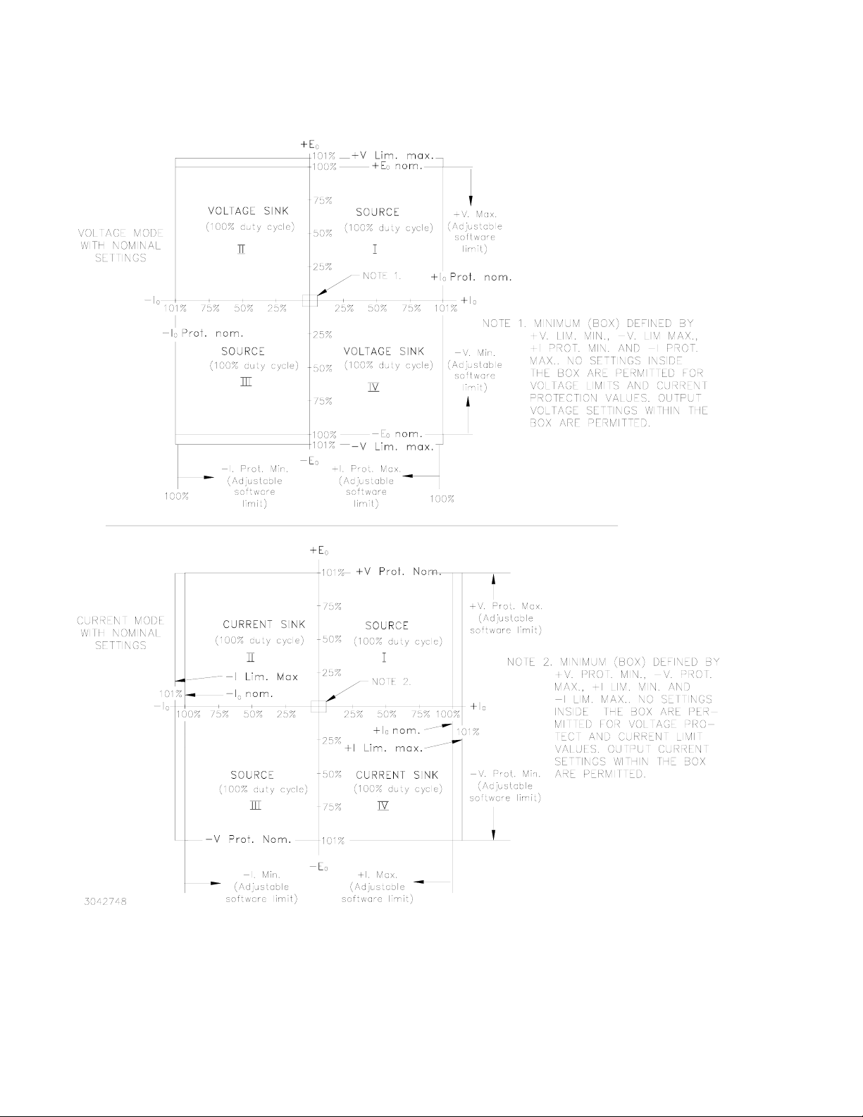
FIGURE 1. BOP-GL OUTPUT CHARACTERISTICS
KEPCO, INC. 131-38 SANFORD AVENUE FLUSHING, NY. 11355 U.S.A. TEL (718) 461-7000 FAX (718) 767-1102
093013 228-1699 REV 2 3
http://www.kepcopower.com email: hq@kepcopower.com
Page 4
IV — ACCESSORIES See Table 3.
TABLE 3. ACCESSORIES
ITEM FUNCTION
Mating Connector, Trigger Mates with Trigger port. 142-0527 (Kepco)
IEEE 1118 (BITBUS)
Mating connector
IEEE 488 Cable, (1 meter long) Connects BOP-GL power supply to GPIB bus. SNC 488-1
IEEE 488 Cable, (2 meter long) Connects BOP-GL power supply to GPIB bus. SNC 488-2
IEEE 488 Cable, (4 meter
longs)
Line Cord (250V, 20A) Provides connection to a-c mains via Nema 6-20P connector. 118-1087
Line Cord (250V, 20A) Provides connection to a-c mains via Nema L6-20P locking type con-
RS 232 Cable Kit Contains RJ11 to RJ45 Patch cord, RJ 45 Patch cord, two RS 232
RS 232 Adapter (Male pins) Allows RS 232 port to be connected to DTE equipment. (Supplied in
RS 232 Adapter (Female pins) Allows RS 232 port to be connected to a PC (personal computer). (Sup-
15-pin DSUB Connector Mating connector for Analog input connector A2A5J6
IDC 6-pin connector Mating connector for RS-232 PORT, connector A1J5 and PROTEC-
IDC 8-pin plug Mating connector for PAR/SER PROTECT PORT (IN and OUT) con-
Slides Allows easy withdrawal of unit from rack (Model CS 04 includes slides,
Heat Sink Provides adequate cooling for calibration sense resistors. 136-0451
Allows connection to IEEE 1118 (BITBUS) port. 142-0485 (Kepco)
Connects BOP-GL power supply to GPIB bus. SNC 488-4
nector.
adapters, one with male pins to connect to DTE equipment and one
with female pins to connect to a PC (personal computer), two RS 232
Loop Back test Connectors (one 6-pin and one 8-pin) to test RS 232
communication and aid in isolating RS 232 communication problems.
KIT 219-0436.)
plied in KIT 219-0436.)
Dsub 15 pin hood
Dsub 15 pin male
TION EXT. PORT, connector A2A5J7
nectors.
brackets, all mounting hardware and installation instructions.)
PART NUMBER
SP2501 (CUI Stack)
KMDLA-5P (Kycon Inc.)
118-1088
KIT 219-0436
142-0487
(L-COM RA098M)
142-0506
(L-COM RA098F)
108-0374
(Tyco-Amp 207470-1)
142-0449
(Amphenol 17S-DA15P)
142-0536
(Amphenol 5-555176-3)
142-0535
(Amphenol 5-555176-3)
CS 04
V — SAFETY See Table 4
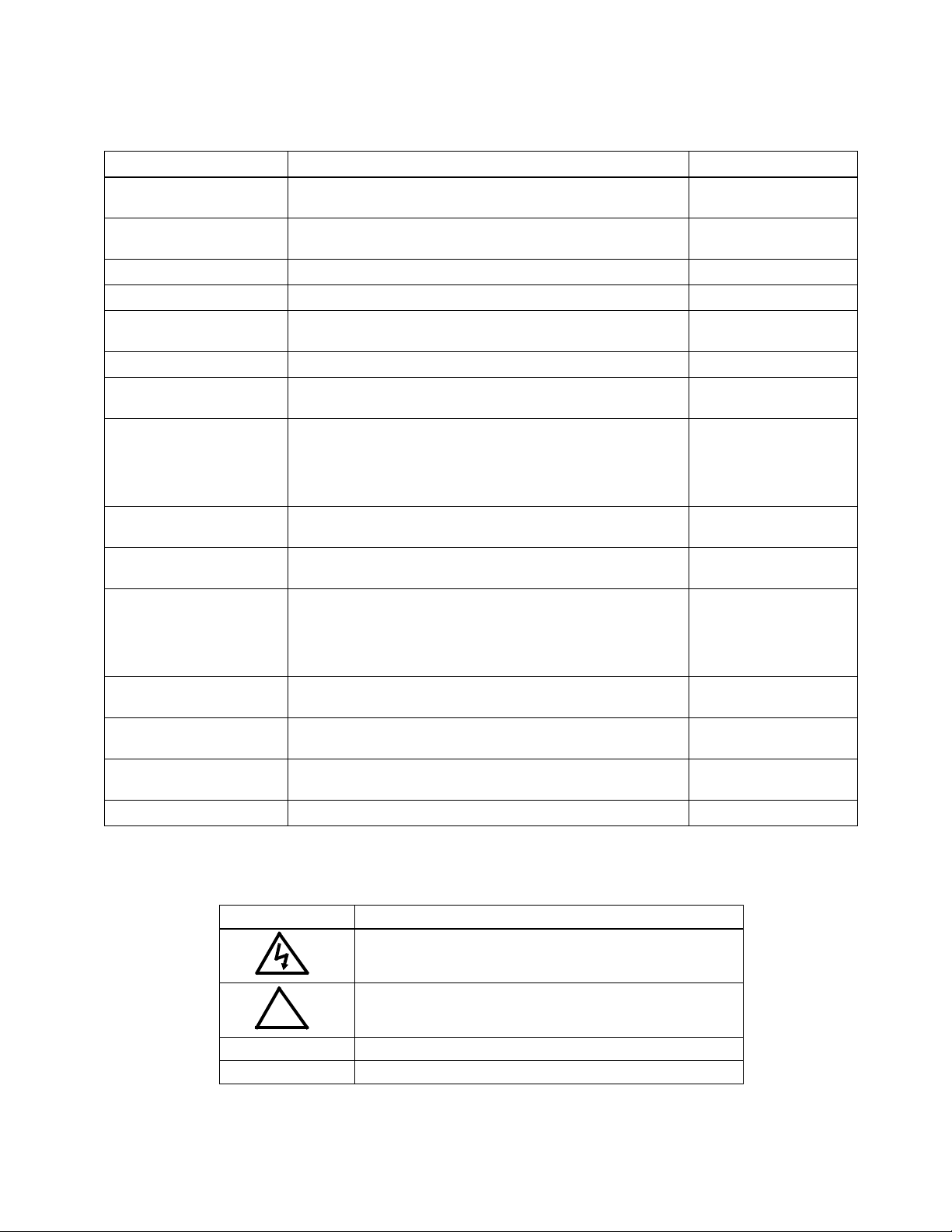
TABLE 4. SAFETY SYMBOLS
SYMBOL MEANING
CAUTION: RISK OF ELECTRIC SHOCK.
CAUTION: REFER TO REFERENCED PROCEDURE.
!
WARNING INDICATES THE POSSIBILITY OF BODILY INJURY OR DEATH.
CAUTION INDICATES THE POSSIBILITY OF EQUIPMENT DAMAGE.
KEPCO, INC. 131-38 SANFORD AVENUE FLUSHING, NY. 11355 U.S.A. TEL (718) 461-7000 FAX (718) 767-1102
4 228-1699 REV 2 093013
http://www.kepcopower.com email: hq@kepcopower.com
Page 5

VI — PRELIMINARY OPERATIONAL CHECK
A simple operational check after unpacking and
before equipment installation is advisable to ascertain whether the power supply has suffered damage
resulting from shipping.
1. With POWER switch set to off position, connect
the power supply to source power (see “Input
Connections” below).
2. Verify that the power-up switches at the top cover
are set to the factory default positions shown in
Figure 5. This establishes GPIB address 6, standalone operation, Voltage mode, Analog Input
enabled and internal ±current limits enabled and
set to maximum.
NOTE: The unit is shipped with load type set to
Active (for inductive loads). To change the
load type refer to the “Reset Power-up” on
page 8. The logic for Remote on/off input
at pin 2 of the Trigger port is set to high (1)
or open circuit for output on, low (0) or
short circuit for output off.
3. Connect a twisted wire pair (either #24 or #22
AWG) to the mating connector for the Analog I/O
port pins 11 and 10. Connect +10V d-c ±0.1mV to
pin 11, referenced to pin 10, then install the mating connector on the Analog I/O port at the rear
panel.
!
4. Connect the power supply to source power. With
no load connected, set POWER switch to the ON
position.
5. Each time the unit is turned on an internal selftest is performed. If the unit passes, it initializes
with the power-up settings established in step 2
and the front panel POWER/FAULT/LIMIT light is
green (power good), the DIGITAL CONTROL light
is not lit (analog input enabled) and the VOLTAGE/CURRENT light is green (voltage mode),
MASTER/SLAVE light is green (standalone or
master configuration) and the OUTPUT ON light
is lit (output enabled). If the front panel POWER/
FAULT/LIMIT light is red, the unit has failed selftest; contact Kepco for further instructions. If the
unit beeps, or the MASTER/SLAVE or VOLTAGE/
CURRENT light blinks, refer to the BOP-GL Operator Manual for troubleshooting.
6. Connect a digital voltmeter (DVM) with resolution
and accuracy of 0.01% or better to the OUT S and
COM S terminals at the rear panel terminal block.
7. Verify DVM voltage reading matches the nominal
voltage of the unit within 0.01% of rated maximum
voltage.
CAUTION:
DO NOT repeatedly toggle the
POWER circuit breaker/switch as
this may damage the unit.
VII — INSTALLATION
Install units either on a bench or in a 19 inch-wide
rack. For rack mounting: first remove four feet; rack
must provide support at the rear. Optional slides
may be used. Leave the front and rear panels clear
of obstructions to ensure adequate cooling.
INPUT CONNECTIONS. Source power is connected to the power supply via three-wire input power using the source power mating connector supplied (see Table 3). This power supply operates from single phase a-c mains power (or between two phases of 3-phase a-c mains power), 230V, 50/60Hz nominal (range: 176 - 264V, 47-63Hz) without any need for range selection. The user must provide a properly sized and rated mains lead (line cord) and service with a current rating compatible with the required input current. Line cords available as accessories are listed in Table 3. Plug the source power connector into the source power inlet connector at the rear panel.
KEPCO, INC. 131-38 SANFORD AVENUE FLUSHING, NY. 11355 U.S.A. TEL (718) 461-7000 FAX (718) 767-1102
http://www.kepcopower.com email: hq@kepcopower.com
093013 228-1699 REV 2 5
LOAD CONNECTIONS.
CAUTION:
!
Before connecting a load, verify
that power up switch settings (see
“Power-up Settings” on page 8) are
compatible with your load.
Power connections require wires that are properly
rated for the nominal output current of the unit. Connect the load to the OUTPUT and COMMON power
terminals on the rear panel (see Figure 3). OUT S
and COM S terminal of the Monitor and Sensing Terminal block are for connection of remote sensing
leads (after removing the factory-installed local
sensing links). NOTE: Output Sense lines must be
connected for proper operation, either locally, or
at the load (remote). Also use OUT S and COM S
to monitor voltage at the load using external equipment such as a DVM, oscilloscope, etc. Use OUT
Page 6

MON and COM MON to monitor voltage at the BOPGL output.
LOCAL SENSING (FACTORY DEFAULT).
Unit is shipped with local sensing links installed:
OUT S connected to OUT MON and COM MON
connected to COM S (see Figure 4A).
REMOTE SENSING SELECT. First remove the factory-installed local sensing links between OUT S and OUT MON and between COM MON and COM S. Then connect the OUT S and COM S lines at the load (see Figure 4B) using #22 AWG wire, twisted pair.
ANALOG I/O CONNECTIONS. The Analog I/O Port connector, located on the rear panel of the BOP-GL 1KW power supply (see Figure 3), provides access to analog programming inputs which can control the mode of operation (voltage or current), output voltage or current, and establish positive and negative voltage and current limits. Output analogs corresponding to output current and voltage are also provided. Refer to Operator’s manual for details.
TRIGGER CONNECTIONS. The Trigger Port (see Figure 3) provides for an external trigger input for use with SCPI *TRG and TRIG commands. Refer to Operator’s manual for details.
GPIB CONNECTIONS. Your computer must have a GPIB interface card installed. Connect the power supply to the computer’s GPIB interface card. Use a standard GPIB interface cable at the GPIB port on the rear panel (see Figure 3). The default GPIB address is 6; refer to the Operator’s Manual to change it.
RS 232 CONNECTIONS. Connect the BOP-GL to a modem using a Null Modem patch cable at the RS 232 port located on the rear panel (See Figure
3). A Null Modem cable is not required for older
MAC computers with D-sub serial port in which the
RXD and TXD line transposition is accomplished via
external hardware. The baud rate (9600 or 19200) is
established by performing a “Reset Power-up” on
page 8.
FIGURE 2. BOP-GL 1KW SERIES, FRONT PANEL CONTROLS AND INDICATORS
KEPCO, INC. 131-38 SANFORD AVENUE FLUSHING, NY. 11355 U.S.A. TEL (718) 461-7000 FAX (718) 767-1102
6 228-1699 REV 2 093013
http://www.kepcopower.com email: hq@kepcopower.com
Page 7

FIGURE 3. BOP-GL 1KW SERIES, REAR PANEL VIEW, LINKS INSTALLED FOR LOCAL SENSING
GND
OUT
N / C OUT
NET
MON
S
GND
COM
MON
COM
S
A. LOCAL SENSING
B. REMOTE SENSING
FIGURE 4. LOAD CONNECTION
KEPCO, INC. 131-38 SANFORD AVENUE FLUSHING, NY. 11355 U.S.A. TEL (718) 461-7000 FAX (718) 767-1102
093013 228-1699 REV 2 7
http://www.kepcopower.com email: hq@kepcopower.com
Page 8

VIII — OPERATION
The user is urged to download the Operator’s manual (see “Accessing Manuals.” on page 1) for complete operating instructions. Some additional
features covered in the Operator Manual are listed
on page 13. In addition, the Operator’s Manual also
covers the GPIB and RS 232 interfaces, including
the use of the drivers downloadable from:
www.kepcopower.com/drivers/drivers-dl3.htm
#bop1k.
POWER-UP SETTINGS Read this before connecting a load!
CAUTION:
!
The unit will power-up as specified
by the power-up switches (see Figure 5). Verify that these switch settings are compatible with your
load. To change any default setting
not covered by this guide, refer to
the Operator’s Manual.
Default settings are in BOLD (other
choices are in italics):
• Load type Active (Battery, Resistive)
• Standalone configuration (Master, Slave)
• Analog Control enabled (disabled)
• Vol tag e mode (Current mode)
• Protection: internal control, ± limit values at
max (1.01 x E
• • (internal control, +limit values at maximum
(1.01 x E
at minimum (box))
• • (internal control, –limit values at maximum
(1.01 x E
+limit values at minimum (box))
• • (External protection limits)
• RS 232 Baud rate 9600 (19.2K)
• GPIB address 6 (0 to 30)
• Trigger port pin 2 remote on/off logic set for:
logic 1 or open = output enabled,
logic 0 or short = output enabled,
logic 0 or short = output disabled
logic 1 or open = output disabled
Onom
Onom
Onom
or I
or I
or I
Onom
Onom
Onom
),
)
), –limit values
S1: 00110 = GPIB ADDRESS 6
S2: 00001 = STANDALONE
S3: 11111 = VOLTAGE MODE, ANALOG INPUT ON
±V and ±C PROTECT MAX SET TO MAXIMUM
FIGURE 5. TOP COVER POWER-UP SWITCHES,
FACTORY DEFAULT SETTINGS
TURNING THE POWER SUPPLY ON.
The status of the unit upon power-up depends on
the configuration of the three power-up switches
(see Figure 5). Each power-up switch has five segments. For convenience the switch settings are often
given for all segments; e.g., 00110 indicates segments 5, 4 and 1 are off (0) and segments 2 and 3
are on (1). In other instances a particular segment
(e.g., S3-5) is specified.
Reset Power-up The reset power-up allows the power-up switches to establish 1) load type, 2) Remote On/off logic at Trigger port pin 2 and 3) RS 232 baud rate. The reset power-up also resets all limits to the factory default condition (overrides limit settings previously saved by MEM:UPD LIM command). If load type, baud rate and Trigger Port remote on/off logic do not need to be changed, refer to “Normal Power-up” on page 9.
1. With power off, refer to Figure 5 and set switches
S1-1 through S1-5 to 1 (GPIB address to 11111)
and set all S3 switches to 0.
2. Set S3 as follows to establish the load type upon
power-up: S3-2 to 1 = Resistive Load, S3-3 to 1 =
Active Load, S3-4 to 1= Battery Load.
3. Set S3-1 to establish the baud rate for RS 232
operation: 1 = 19.2K, 0 = 9600.
4. Set S3-5 to 0 if desired to reverse the logic of the
Remote On/Off signal at pin 2 of the External Trigger Port from the default (logic 1 = output
enabled, logic 0 = output disabled) to logic 0 =
output enabled, logic 1 = output disabled.
5. Do not change S2 settings.
KEPCO, INC. 131-38 SANFORD AVENUE FLUSHING, NY. 11355 U.S.A. TEL (718) 461-7000 FAX (718) 767-1102
http://www.kepcopower.com email: hq@kepcopower.com
8 228-1699 REV 2 093013
Page 9

CAUTION:
!
DO NOT repeatedly toggle the circuit breaker/switch as this may
damage the unit.
6. Set POWER ON/OFF circuit breaker/switch on
front panel to ON. If actuator does not lock when
released, wait a few seconds before trying again.
The circuit breaker is “trip-free” design; if overload
exists, contacts cannot be held closed by actuator.
7. The unit will begin beeping on and off at equal
intervals. Set POWER ON/OFF circuit breaker/
switch on front panel to OFF and proceed to normal power-up (see below) to complete power-up
configuration.
Normal Power-up The normal power-up establishes the operating mode of the unit, whether control will be analog or digital, whether the unit is standalone or part of a multi-unit configuration, and selects the GPIB address to be used.
1. With power off, set power-up switches S1, S2 and
S3 as follows (see Figure 5):
a. Set S3 to 11111 to establish voltage mode,
analog input on, ±V Protect Max and ±C Protect Max set to maximum (change S3-1 to 0 for
current mode, change S3-4 to 0 for Analog
Input off).
b. Set S2 to 00001 to select standalone opera-
tion.
c. Set S1 with valid GPIB address from 0 to 30.
S1-1 through S1-5 is 2
GPIB address is 00110 = 6.
CAUTION:
0
through 24. Default
!
DO NOT repeatedly toggle the circuit breaker/switch as this may
damage the unit.
3. Unit performs self-test upon power-up initialization. If the unit passes self-test, the POWER/
FAULT/LIMIT light turns green and the unit is
ready for operation; if it fails, the light turns red.
POWER SUPPLY BASICS. When in Voltage mode, the power supply will (within the configured and rated limits) provide the programmed output voltage. Current is determined by the load, and cannot exceed the Current Protect limits. If the protect limit is reached, the POWER/FAULT/LIMIT LED light changes from green (power OK) to orange.
When in Current mode, the power supply will (within
the configured and rated limits) provide the programmed output current. Voltage is determined by
the load, and cannot exceed the Voltage Protect limits. If the protect limit is reached, the POWER/
FAULT/LIMIT LED light changes from green (power
OK) to orange.
VOLTAGE AND CURRENT PARAMETERS.
Table 5 defines the voltage and current parameters
used in this manual and provides references to the
SCPI commands and queries associated with the
parameter.
SETTING VOLTAGE OR CURRENT MODE.
The BOP-GL uses two separate channels, one to
set output voltage or current and one to set the corresponding protection limit. The main channel is
determined by the power-up switches during normal
power-up:
Voltage Mode: S3-5 = 1, S3-1 = 1
Current Mode: S3-5 = 1, S3-1 = 0
The protection channel is determined automatically
by the main channel selected. When Voltage mode
is selected, the current protection channel is in use,
and when Current mode is selected, the Voltage
protection channel is in use.
2. Set POWER ON/OFF circuit breaker/switch on
front panel to ON. If actuator does not lock when
released, wait a few seconds before trying again.
The circuit breaker is “trip-free” design; if overload
exists, contacts cannot be held closed by actuator.
KEPCO, INC. 131-38 SANFORD AVENUE FLUSHING, NY. 11355 U.S.A. TEL (718) 461-7000 FAX (718) 767-1102
093013 228-1699 REV 2 9
http://www.kepcopower.com email: hq@kepcopower.com
Page 10

TABLE 5. VOLTAGE AND CURRENT PARAMETER DEFINITIONS
Term Definition
+E
Onom
–E
Onom
+I
Onom
–I
Onom
+Voltage
–Voltage
+Voltage max
–Voltage min
+Current Protect
–Current Protect
+Current Protect Max
–Current Protect Min
Minimum (box)
+Current Protect Min
–Current Protect Max
The nominal (rated) output voltage of the unit determined by model; e.g. for
a BOP 36-28GL, ±E
Onom
is 36V.
The nominal (rated) output current of the unit determined by model; e.g. for
a BOP 36-28GL, ±I
Onom
is 28A.
Voltage mode only. Positive (+) and negative (–) output voltage values
established by remote command.
Range (+): 0 to +Voltage max
Range (–): 0 to –Voltage min
Voltage mode only. Maximum (positive) and minimum (maximum
negative) voltage that can be set.
Value (+): 0 to +E
Value (–): 0 to –E
Onom
Onom
Voltage mode only. Defines maximum (+) current and Minimum (maximum
negative) (–) that unit can source or sink.
Range (+): +Current Protect min to +Current Protect max
Range (–): –Current Protect max to –Current Protect min
Voltage mode only. Maximum setting for +Current Protect and Minimum
(maximum negative) setting for –Current Protect.
Value (+): +Current Protect min to (1.01 x +Current max)
Value (–): –Current Protect max to (1.01 x –Current min)
Voltage mode only. Minimum (positive) setting for +Current Protect and
maximum (maximum negative) setting for –Current Protect. Values of ±Current Protect between +Current Protect Min and –Current Protect Max (near
zero) are not allowed.This zone (also referred to as the minimum (box) is
automatically calculated by the BOP (see Figure 1).
Associated SCPI
command/query
N/A
N/A
VOLT
VOLT:LIM[:BOTH]
VOLT:LIM:NEG
VOLT:LIM:POS
CURR:PROT
CURR:PROT:NEG
CURR:PROT:POS
CURR:PROT:LIM
CURR:PROT:LIM:NEG
CURR:PROT:LIM:POS
N/A
+Voltage Protect
–Voltage Protect
+Voltage Protect Max
–Voltage Protect Min
Minimum (box)
+Voltage Protect Min
–Voltage Protect Max
+Current
–Current
+Current max
–Current min
Current mode only. Maximum positive (+) and minimum (maximum
negative) (–) voltage that can appear at the output.
Range (+): +Voltage Protect min to +Voltage Protect max
Range (–): –Voltage Protect max to –Voltage Protect min
Current mode only. Maximum (positive) setting for +Voltage Protect and
Minimum (maximum negative) setting for –Voltage Protect.
Value (+): +Voltage Protect min to (1.01 x +Voltage max)
Value (–): –Voltage Protect max to (1.01 x –Voltage min)
Current mode only. Minimum (positive) setting for +Voltage Protect and
maximum (maximum negative) setting for –Voltage Protect. Values of ±Voltage Protect between +Voltage Protect Min and –Voltage Protect Max (near
zero) are not allowed. This zone (also referred to as the minimum (box) is
automatically calculated by the BOP (see Figure 1).
Current mode only. Positive and negative output current established by
remote command.
Range (+): 0 to +Current max
Range (–): 0 to –Current min
Current mode only. Maximum (positive) and minimum (maximum
negative) current that can be set.
Value (+): 0 to +I
Value (–): 0 to –I
Onom
Onom
VOLT:PROT
VOLT:PROT:NEG
VOLT:PROT:POS
VOLT:PROT:LIM
VOLT:PROT:LIM:NEG
VOLT:PROT:LIM:POS
N/A
CURR
CURR:LIM
CURR:LIM:NEG
CURR:LIM:POS
KEPCO, INC. 131-38 SANFORD AVENUE FLUSHING, NY. 11355 U.S.A. TEL (718) 461-7000 FAX (718) 767-1102
http://www.kepcopower.com email: hq@kepcopower.com
10 228-1699 REV 2 093013
Page 11

VOLTAGE/CURRENT PROTECT LIMITS (LIMIT CHANNEL SOFTWARE LIMITS).
These values are the references for the complementary channels: voltage in current mode and current in
voltage mode. The range for these values is
between a minimum (box) value (see Figure 1) and
1% above the rated nominal value. If the unit is in
voltage mode, it will enter current protect mode
when the load demands more current and energy
than permitted by the ±current protect settings. Similarly, if the unit is in current mode, it will enter voltage
protect mode if the load demands more voltage and
energy than permitted by the ±voltage protect settings. When the protect settings are exceeded, the
protection channel limits the output current or voltage, the POWER/FAULT/LIMIT LED lights orange
(LIMIT), and the power supply continues operation
in the complementary mode of operation.
The BOP can be configured to program the protection limits as a single value that applies to both protection channels (using CURR:PROT:LIM or
VOLT:PROT:LIM) or by individual commands:
(CURR:PROT:LIM:POS, CURR:PROT:LIM:NEG,
VOLT:PROT:LIM:POS, VOLT:PROT:LIM:NEG) to
program individual settings for positive and negative
protection limits.
SOFTWARE LIMITS. The software limits for the main channels (+Voltage Max, –Voltage Min, +Current Max and –Current Min) are the maximum (positive) and minimum (Maximum negative) values allowable for voltage and current. The default software limits are determined by the model: the nominal (rated) values for voltage and current (e.g., 36V and 28A for the BOP 36-28GL). These four values can be adjusted independently. For example, a BOP 36-28GL, capable of delivering ±36V in voltage mode can be configured to allow voltage to be adjusted only from –1V to +15V by setting –Voltage Min to –1 and +Voltage Max to +15. This can be done by sending
VOLT:LIM:NEG 1 commands
VOLT:LIM:POS 15 and
via either GPIB or RS
232 ports.
NOTE: If main channel software limits are changed
from the default, the corresponding protection limits
are automatically set to 1% above the new maxi-
mum value. The complementary software limits are
unchanged - they must be changed manually if
needed.
MAXIMUM/MINIMUM PROTECTION LIMITS (SOFTWARE-CONTROLLED).
tection limits are software limits that establish the maximum and minimum (maximum negative) allowable
levels of output voltage in current mode and current in
voltage mode. The default protection limits are 1%
above E
Omax or
1% above I
CAUTION:
Omax
.
The ± pro-
!
When working with active loads,
always adjust the BOP protection
limits to be above the maximum
values of voltage or current
expected from the load. For example, when the BOP is operating in
voltage mode sinking energy from
a constant current type load, set
the current protection limits of the
BOP above the maximum current
expected from the load.
The protect channel limits are +V (voltage) Protect
max, –V Protect min, +C (current) Protect max and –C
Protect min (see Table 5); these prevent the unit from
sourcing or sinking voltage or current that exceeds
these settings. In voltage mode the current protect
channel is clamped to the limit value; in current mode
the voltage protect channel is clamped to the limit
value. Adjustment range is between a minimum (box)
value (see Figure 1) and 1% above the nominal (rated)
value.
DETERMINING HOW THE UNIT RESPONDS WHEN OUTPUT IS OFF (LOAD TYPE). The
BOP-GL supports three Load Type selections which
determine how the power supply responds when the
output is off: ACTIVE, RESISTIVE and BATTERY
(see Table 6). The Load Type selection does not
affect the settings of the power supply for ON state;
it only affects the main internal reference level and
the protection levels during the OFF state. Load type
is selected by performing a Reset Power-up or by
using the OUTP:MODE command.
KEPCO, INC. 131-38 SANFORD AVENUE FLUSHING, NY. 11355 U.S.A. TEL (718) 461-7000 FAX (718) 767-1102
093013 228-1699 REV 2 11
http://www.kepcopower.com email: hq@kepcopower.com
Page 12

TABLE 6. POWER SUPPLY BEHAVIOR WHEN OUTPUT IS SET TO OFF
LOAD TYPE
SETTING
ACTIVE
RESISTIVE
BATTERY
If unit was in Voltage Mode when output OFF
command issued.
• Unit remains in voltage mode.
• Voltage set to zero.
• Both ± Current Protect set to maximum.
• Both ± Voltage Limit remain at maximum.
• Unit remains in voltage mode.
• Voltage set to zero.
• Both ± Current Protect set to minimum box values.
• Both ± Voltage Limit remain at maximum.
• Unit set to current mode.
• Current set to zero.
• Both ± Voltage Protect remain at maximum.
• Both ± Current Limit set to maximum.
WARNING
For inductive loads, and especially
superconducting magnet type
loads, the inherent offset of the
BOP-GL in the OFF state may generate significant current in the circuit. A properly rated switch in
parallel with a resistor must be
connected between the power supply and the load. The switch must
be open and voltage and current
measurements at the output must
read 0V, 0A before removing or
installing connections between
BOP and load.
Active. Active mode (default setting) is necessary
for the power supply to function properly and safely
with inductive loads and constant-current-type active
electronic loads. Active mode can also be used with
resistive loads. Table 6 indicates how the power supply responds to a command to go from Output ON to
OFF. When the output is disabled, the unit is set to
voltage mode, voltage is set to zero and both current
protect and voltage limit are set to maximum. When
the unit is enabled, the pre-existing settings for voltage, current protect and voltage limit are restored.
WARNING
For both inductive loads and constant-current-type active electronic
loads, when the BOP-GL output is
set to OFF, a path is provided for
absorbing either the energy accumulated in the reactance of the
load during the ON state, or energy
If unit was in Current Mode when output OFF
command issued.
• Unit set to voltage mode.
• Voltage set to zero.
• Both ± Current Protect remain at maximum.
• Both ± Voltage Limit set to maximum.
• Unit remains in current mode.
• Current set to zero.
• Both ± Current Protect set to minimum box values.
• Both ± Voltage Limit set to maximum,
• Unit remains in current mode,
• Current set to zero.
• Both ± Voltage Protect set to maximum.
• Both ± Current Limit remain at maximum.
delivered by an electronic load.
This prevents damage to the load
and power supply as well as providing safety for the user. However,
in addition to the built-in safety features, constant-current-type active
electronic loads must be adjusted
to zero and voltage and current
measurements at the output must
read 0V, minimum current, before
handling the power supply-to-load
connections.
Resistive. This mode, as the name suggests, is
useful for resistive loads. Table 6 indicates how the
power supply responds to a command to go from
Output ON to OFF.
WARNING
Accessing the BOP-GL after the
output is disabled in BATTERY
mode is hazardous because (1)
high current arcing is possible and
(2) either the external battery voltage, or the voltage (±Voltage Protection max) on the BOP-GL output
terminals may be dangerous.
Therefore, for battery and constantvoltage-type active electronic loads
it is recommended that two properly rated external switches be
installed for safety: one in series
with the battery, and one across the
BOP-GL output. After the unit is set
to OFF, first open the switch in
series with the battery, then close
KEPCO, INC. 131-38 SANFORD AVENUE FLUSHING, NY. 11355 U.S.A. TEL (718) 461-7000 FAX (718) 767-1102
http://www.kepcopower.com email: hq@kepcopower.com
12 228-1699 REV 2 093013
Page 13

the switch across the BOP-GL output to ensure safety before handling BOP-GL connections. When
connecting the battery, the switch
across the output should be
opened after the connections are
complete and then the switch in
series with the battery should be
closed. If the constant-voltage-type
active electronic load is adjusted to
zero before handling the power
supply-to-load connections, only
the switch across the BOP-GL output is required.
Battery. This mode is necessary for the power sup-
ply to function properly and safely with either battery
or constant-voltage-type active electronic loads.
This mode prevents the battery from discharging
during the OFF state. When the output is disabled
(set to OFF), the BOP-GL will go to current mode,
current will be set to zero, with voltage protect and
current limit set to maximum. In this way the battery
will not be discharged while the output is OFF. For
constant-voltage-type active electronic loads this
mode stops energy flow during the OFF state. Table
6 indicates how the power supply responds to a
command to go from Output ON to OFF.
CONFIGURE LOAD TYPE. To configure, perform “Reset Power-up” on page 8 and change S3 as desired.
ENABLING/DISABLING OUTPUT POWER.
The behavior of the unit when disabled depends on
the Load Type setting (see Table 6 for details). There
are four ways to disable the output, refer to Operator
Manual for details:
1. Using Remote Shutdown pin 2 (referenced to pin
1) of the Protection Ext. port. This faults the unit,
and requires the unit to be turned off, then on in
order to restore operation.
2. Using Remote On-Off at pin 2 (referenced to pin
1) of the Trigger port which sets the output to off
(disabled) or on (enabled) by toggling a signal
applied to the Trigger port. This requires sending
either:
a. OUT:CONT:HIGH: output on if pin 2 open or
high, output off if pin 2 shorted or low.
b. OUT:CONT:LOW: output on if pin 2 shorted or
low, output off if pin 2 open or high.
3. Using Remote On-Off at pin 2 (referenced to pin
1) of the Trigger port to disable the output and the
digital command OUTP ON to enable the output.
This requires first sending OUTP:CONT:STAN
command.
4. Using digital commands OUTP OFF and OUTP
ON to disable and enable the output. This
requires first sending OUTP:CONT:STAN command.
IX — ADDITIONAL FEATURES
The user is urged to refer to the Operator’s Manual
for full explanations of all BOP-GL 1KW features,
including:
• Changing the Default Power up Settings.
• Remote Shutdown.
• Digital Remote Operation - using SCPI commands via RS 232 or GPIB ports.
• Analog Remote Operation - via Analog I/O
port.
• Details about Protect Limits and Softwarecontrolled limits.
KEPCO, INC. 131-38 SANFORD AVENUE FLUSHING, NY. 11355 U.S.A. TEL (718) 461-7000 FAX (718) 767-1102
http://www.kepcopower.com email: hq@kepcopower.com
093013 228-1699 REV 2 13
• Storing/Recalling Power Supply Output Settings.
• Waveform Generation - Sine, Triangle,
±Ramp, Square and Level segments. Remote
operation allows 1 waveform, maximum of
126 segments using LIST commands.
• Operator Testing.
• Calibration - via remote SCPI commands.
• Parallel/Series Configurations -increase current capability, voltage capability, or both.
Page 14

18.805 [477.63]
18.018 [457.64]
17.675 [448.93]
16.835 [427.60]
]
]
]
1
0
4
]
]
]
9
2
3
7
1
7
.
.
.
8
6
7
5
0
4
5
6
5
[
[
[
0
3
4
0
6
6
0
8
5
.
.
.
2
3
1
2
2
2
]
5
1
.
4
4
[
8
3
7
.
1
1
0
5
.
.
.
9
8
4
7
0
4
5
5
5
[
[
[
0
0
9
0
0
3
8
0
4
.
.
.
2
0
1
2
2
2
OBROUND 0.25x0.453 (4 LOC.)
]
4
5
.
2
3
1
[
8
1
2
.
5
]
4
3
.
7
3
[
0
7
4
.
1
18.235 [463.16]
18.985 [482.21]
]
7
2
.
6
5
[
5
1
2
.
2
FIGURE 6. BOP 1KW OUTLINE DIMENSIONS (SHEET 1 OF 2)
KEPCO, INC. 131-38 SANFORD AVENUE FLUSHING, NY. 11355 U.S.A. TEL (718) 461-7000 FAX (718) 767-1102
http://www.kepcopower.com email: hq@kepcopower.com
14 228-1699 REV 2 093013
Page 15

SEE DETAIL "A".
REAR VIEW
22.000 [558.79]
SLIDES TRAVEL DISTANCE: 23.000 [584.2]
SEE NOTE 6.
DETAIL "A"
FIGURE 6. BOP 1KW OUTLINE DIMENSIONS (SHEET 2 OF 2)
KEPCO, INC. 131-38 SANFORD AVENUE FLUSHING, NY. 11355 U.S.A. TEL (718) 461-7000 FAX (718) 767-1102
093013 228-1699 REV 2 15
http://www.kepcopower.com email: hq@kepcopower.com
Page 16

KEPCO, INC. 131-38 SANFORD AVENUE FLUSHING, NY. 11355 U.S.A. TEL (718) 461-7000 FAX (718) 767-1102
http://www.kepcopower.com email: hq@kepcopower.com
16 228-1699 REV 2 093013
 Loading...