

Page 1

SC-IF Series
Current to Frequency Signal Conditioner
http://www.kep.com
99820 07/23/01
KESSLER-ELLIS PRODUCTS
10 Industrial Way East
Eatontown, NJ 07724
800-631-2165 • 732-935-1320
Fax 732-935-9344
Page 2

INDEX
DESCRIPTION ..................................................................................1
SPECIFICATIONS.............................................................................1
OUTPUT SETTINGS.........................................................................2
LED INDICATORS..................................................................2
OUTPUT ADJUSTMENTS .....................................................2
DIMENSIONS....................................................................................3
WARRANTY ......................................................................................3
DECODING PART NUMBER ............................................................3
Page 3

SC-II Signal Conditioner
Description:
The SC-IF loop powered signal conditioner whose function
is to provide a 0 - 10kHz frequency output signal in response
to a 4-20 analog input.
The SC-IF appears to the input loop as a series shunt
resistor. A small sense resistor is used to measure the input
current. The input loop derives it’s power from the input
current loop.
This input current signal is then scaled and converted to a 0
to 10,000 Hz frequency signal by a Current to Frequency
Converter. This frequency signal is then transmitted across
an opto-isolator to the output stage.
The 10-50 mA range option is provided to enable the unit to
perform range conversions as well as signal isolation.
Specifications:
Analog Input
Available Ranges: 4-20 mA (10-50 mA optional)
Input Type: Two Wire, Loop Powered
Equivalent Input Impedance: 525 Ω on 4-20 mA range
210 Ω on 10-50 mA range
Operational Range: 3.5-33 mA
Over Current Protection: 2.5 times rated span
Reverse Polarity Protection
Isolation Voltage: 500 V
Input Loop Indicator: LED illuminates when loop is pow-
ered by proper polarity
Pulse Output Option
Output Type: Open Collector Transistor
Low Cutoff: 1% of full scale
Range: 0 to 10,000 Hz
Duty Cycle: 50/50 Duty Cycle (nominal)
Maximum Off Voltage: 30 VDC
Minimum On Current: 10 mA
Maximum On Voltage: 1 VDC
Temperature Effect: Less than 200 ppm/degree C
Reverse Polarity Protection
Mounting Styles
DIN Rail Mount: Plastic enclosure with a snap fastener
for fitting to DIN 46 277 and DIN EN 50
022 assembly rails.
NEMA 4: 4.92" x 4.92" NEMA 4 Enclosure for wall
mounting.
Explosion Proof: Aluminum enclosure for:
Class I, Division 1, Groups B, C & D
Class II, Division I, Groups E, F & G.
Listing: CE Compliant
Terminal Designations:
1• 4-20mA INPUT +
2• 4-20mA INPUT 3• N/C
4• N/C
5• N/C
6• N/C
7• DC Power (+)
8• Pulse Output
9• DC Power (-) / Pulse Output (-)
Simplified Block Diagram
+
1
4-20mA
Input
Loop
2
–
Span
I/F
Zero
+ 24 VDC
7
Open Collector
8
9
Common
Typical Wiring Hookup
+
4-20mA
Output
4-20 mA Output Device
1
–
SC-IF
1
2
+24 V
7
Open Collector Output
8
Common
9
24 VDC Out
Pulse Input
Common
Pulse Input Device
Page 4
SC-II Signal Conditioner
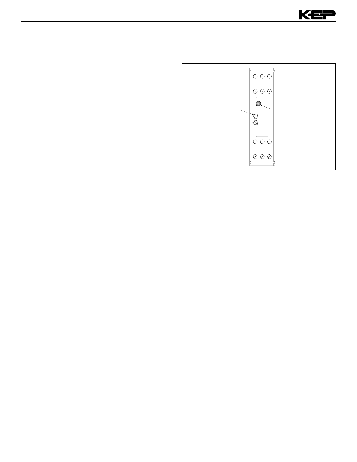
OUTPUT SETTINGS
LED INDICATOR:
The SC-IF has an LED indicators. The LED illuminates when at
least 4mA is connected to the unit. The sole LED indicates that
the unit is loop powered. To calibrate the unit, input 4mA and
connect a frequency meter or rate indicator to the output.
FIGURE 1:
OUTPUT ADJUSTMENTS:
The unit has two potentiometers for adjustment. The lower
potentiometer controls the 4mA set point and the uppers
potentiometer controls the 20mA set point. To adjust the output,
connect 4mA and adjust the lower potentiometer to obtain 0Hz.
Then connect 20mA and adjust the upper potentiometer to obtain
10kHz.
SPAN Adjust
(CCW-Up, CW-Down)
ZERO Adjust
(CCW-Down, CW-Up)
1 2 3
7 8 9
INPUT LED
INDICATOR
2
Page 5

Dimensions
SC-II Signal Conditioner
WARRANTY
This product is warranted against defects in
materials and workmanship for a period of two
(2) years from the date of shipment to Buyer.
.89
(22.5)
Mounting holes molded
directly under cover screws.
Max. screw head .29"
(Typ. 4 places)
4.21
(107)
PANEL INSTALLED
4.21
(107)
4.92
(125)
TOP VIEW
4.9 - 5.25
(124 - 133)
1.40 (35.5)
2.95 (75)
To access terminals, remove
cover and 4 panel screws.
4.92
(125)
.43
(11)
.18 (5)
SIDE VIEW
3/4” NPT (2) HLS.
(feed thru hubs)
3.88 (98.5)
2.95
(75)
1.93
(49)
The Warranty is limited to repair or replacement of the defective unit at the option of the
manufacturer. This warranty is void if the product has been altered, misused, dismantled, or
otherwise abused.
ALL OTHER WARRANTIES, EXPRESSED
OR IMPLIED, ARE EXCLUDED, INCLUDING
BUT NOT LIMITED TO THE IMPLIED WARRANTIES OF MERCHANTABILITY AND FITNESS FOR A PARTICULAR PURPOSE.
Kessler - Ellis Products Co.
10 Industrial Way East
Eatontown, NJ 07724
(732) 935- 1320
Toll Free 800 - 631 - 2165
Fax (732) - 935 - 9344
www.kep.com
Decoding Part Number
Example SC-IF D ET
Series
IF= Current to Frequency
5.9 - 7.7
(150 - 196)
4.75 -5
(121 - 127)
Optional 3rd
Conduit Entry
All Dimension in inches (mm)
Mounting:
B= Nema 4X
C= Explosion Proof
D= DIN Rail
Options:
ET= Extended Temp (-20° to 85° C)
Accessories: (add to end of part number)
DR-4= 4" DIN Rail
3
 Loading...