


BATCHtrol-II

99392 05/21/08
Description
The Batcher is a programmable, microprocessor based unit which provides batch control, monitors ow
rate and controls the ow of processing liquids. Start/Stop controls can be used in conjunction with pre-
warn and nal relays to provide valve actuation or pump control. An optional conguration offers stream-
lined preset adjustments, remote Start, Stop & Reset, and weighted averaging.
Features
❑ Pulse or Analog Input
❑ Display Batch, Rate or Grand Total
❑ Pulse Count Input up to 20 KHz
❑ 16 Point Linearization
❑ 8 Digit K-Factors for Rate and Total
❑ Security Lockout
❑ 2-Way RS232/422 Communications
❑ NEMA 4X/IP65 Front Panel
❑ Scalable 4-20 mA Output
❑ Scaled Pulse Output
❑ Optional Conguration Includes:
- Streamlined Preset Adjustment (Easy Preset)
- Remote Start, Stop and Reset
- Weighted Averaging
Application
The unit is normally used for batch control or inventory tracking. The display may be toggled between
batch, rate, and grand total. A programmable K-factor makes keying-in engineering units easy. The unit
accepts pulse, contact closures or analog inputs and provides two separate preset controls.
BATCHtrol II
Principle of Operation
The batcher receives an input from a pulse producing owmeter through a sensor. The user programs
the batcher to condition the incoming pulses signal and compute the batch ow and ow rate. A wide
variety of different functions can then be performed based on the programmed congurations such as
start/stop functions, totalizing, and/or ow rate monitoring. Several other inputs, outputs and functions are
available.
BATCHtrol II Series Technical Manual
Kessler-Ellis Products Co.
BATCHtrol II
Software Versions 8.x & 12.x
Installation and Operating Manual

!
SAFETY INSTRUCTIONS
The following instructions must be observed.
• This instrument was designed and is checked in accordance with
regulations in force EN 60950 (“Safety of information technology
equipment, including electrical business equipment”).
A hazardous situation may occur if this instrument is not used for
its intended purpose or is used incorrectly. Please note operating
instructions provided in this manual.
• The instrument must be installed, operated and maintained by
personnel who have been properly trained. Personnel must read
and understand this manual prior to installation and operation of the
instrument.
• The manufacturer assumes no liability for damage caused by incorrect
use of the instrument or for modications or changes made to the
instrument.
Technical Improvements
• The manufacturer reserves the right to modify technical data without
prior notice.

1. INTRODUCTION
1-1 General Description ..................................................................................................1
1-2 Typical Application ....................................................................................................1
1-3 Principles of Operation .............................................................................................1
1-4 STD PRE and EZ PRE Operation Modes ................................................................3
1-5 Specications ...........................................................................................................4
1-6 Dimensions ...............................................................................................................5
2. INSTALLATION
2-1 Receipt of Equipment ...............................................................................................6
2-2 Return Shipment.......................................................................................................6
2-3 Panel Mounting.........................................................................................................6
2-4 Electrical Connections ..............................................................................................6
2-5 Wiring Connections and Diagrams ...........................................................................7
3. OPERATION
3-1 Front Panel Operation ..............................................................................................8
3-2 VER 8.7 Programming..............................................................................................9
3-3 VER 8.7 K-Factor Programming ...............................................................................9
3-4 Software Version 8.7 Programming Flow Chart .....................................................10
3-5 VER 12.0 Programming..........................................................................................11
3-6 VER 12.0 16 Point Linearization Notes .................................................................. 11
3-7 Software Version 12.0 16 Pt. Programming Flow Chart .........................................12
3-8 How to Program......................................................................................................13
3-9 Frequently Asked Questions About Setting Up The Batcher ..................................13
3-10 Setup Procedure For The Batcher ........................................................................14
3-11 Run Mode .............................................................................................................27
3-12 Internal Operation .................................................................................................29
4. INPUTS
4-1 Digital Pulse Inputs .................................................................................................30
4-2 Analog Inputs ..........................................................................................................30
4-3 DC Power Inputs ....................................................................................................32
4-4 AC Power Inputs .....................................................................................................32
5. OUTPUTS
5-1 Frequency Output ...................................................................................................32
5-2 Control Outputs ......................................................................................................33
5-3 Optional Analog Output ..........................................................................................33
5-4 Optional RS232 / RS422 Serial Communications ..................................................34
CONTENTS

6. TROUBLE SHOOTING AND MAINTENANCE GUIDE
6-1 Warning Messages .................................................................................................34
6-2 Troubleshooting ......................................................................................................35
6-3 Removing The Case ...............................................................................................36
6-4 Maintenance ...........................................................................................................36
7. CALCULATING THE K FACTORS
7-1 General ...................................................................................................................36
7-2 Calculating the K Factors .......................................................................................37
7-3 Calculating 16 Point K Factors ...............................................................................39
8. SERIAL COMMUNICATIONS
8-1 Unit Code................................................................................................................40
8-2 Baud Rate...............................................................................................................40
8-3 Parity ......................................................................................................................40
8-4 RS232 Electrical Requirements..............................................................................40
8-5 RS232 Card Wiring.................................................................................................41
8-6 RS422 Electrical Requirements..............................................................................41
8-7 RS422 Card Wiring.................................................................................................42
8-8 Strobe Input Electrical Requirements .....................................................................42
8-9 Strobe Wiring ..........................................................................................................43
8-10 Serial Interface Operation.....................................................................................43
8-11 Strobe Address Operation ....................................................................................45
9. Programming Worksheet
.................................................................................................46
CONTENTS
1
SECTION 1 INTRODUCTION
1-1 General Description
Sections 1 through 8 of this manual describe
the wiring, programming and functionality of
the standard Batch controller. Section 9 de-
scribes the wiring, programming and function-
ality of Batch controllers with software version
8.7 (Option 6). Software version 8.7 incor-
porates Remote Start, Stop & Reset with EZ
PRE (easy preset). EZ PRE is a useful tool
for applications that require frequent changes
to the Preset amount.
The Batch controller uses the following soft-
ware versions:
VER 8.7 (Basic unit; Remote Start, Stop
& Reset with EZ PRE “Easy
Preset”)
VER 12.0 (Option 4; 16 point linearization)
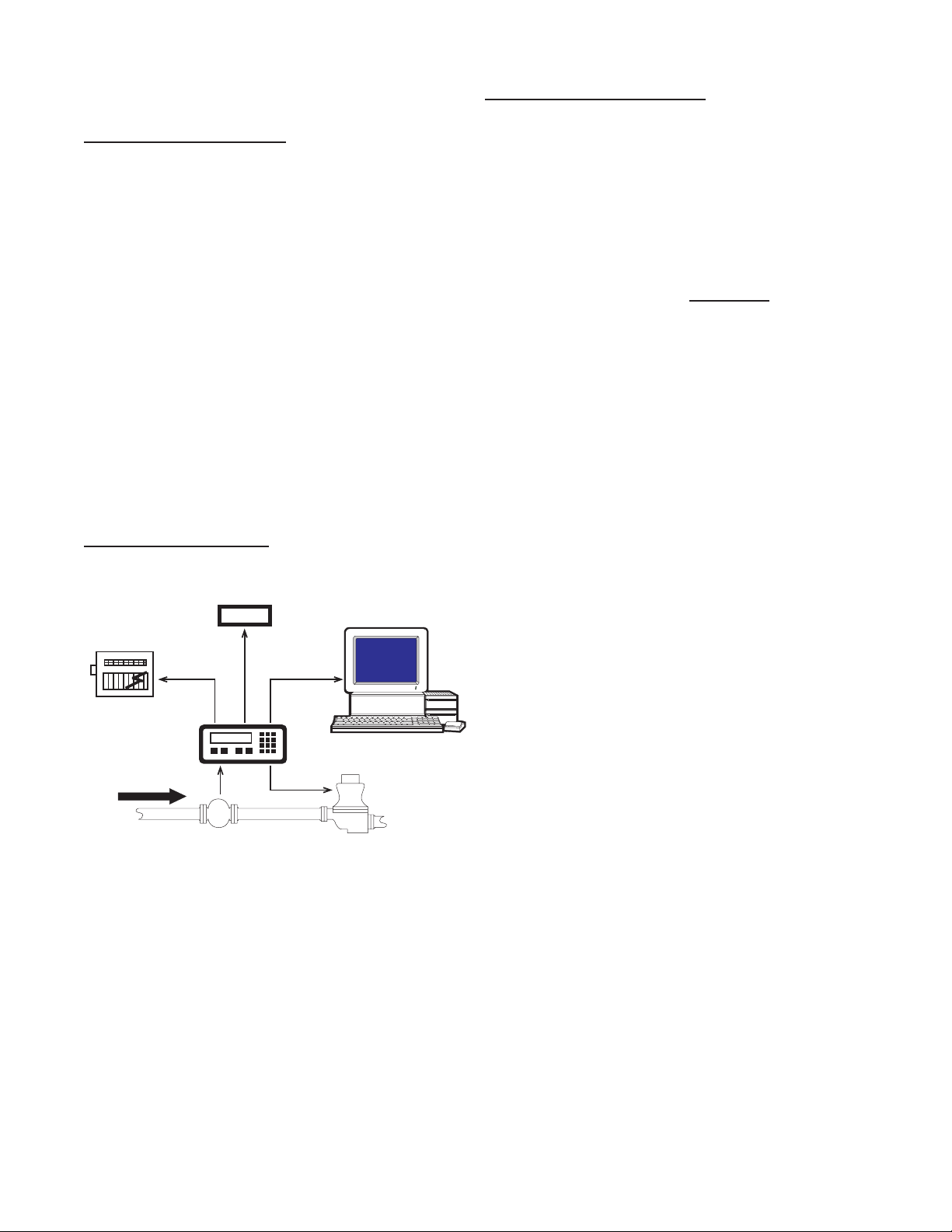
1-2 Typical Application
The above application involves liquid ow.
The start button is pushed and the Batcher
receives pulses from the owmeter. The puls-
es are scaled by the K Factor and sent out via
the pulsed output to an external counter. The
Analog output is directed to a strip chart re-
corder which gives a hardcopy of the rate. As
the Prewarn is reached, the control valve par-
tially closes. When the nal Preset is reached
the valve shuts down completely. At any time
the ow can be suspended by hitting the stop
button. Through the serial communications, a
computer keeps a record of the daily events.
123456
Flowmeter
Computer
Solenoid Valve
Remote
Totalizer
Strip Chart
Recorder
Pulse Output
RS232
Output
Analog
Output
1-3 Principles of Operation
Presets
When the start button is pushed, two relays
engage simultaneously to start ow. When
the prewarn number is reached, one re-
lay drops out. When the preset number is
reached, the other relay drops out. The user
may enter the two numbers when setting up
the batch counter. The prewarn is set a cer-
tain number of counts less than the preset
number. If the prewarn is set larger than the
preset, the message “PREWRONG” will ap-
pear on the display.
Ratemeter
Accurate to 5 1/2 digits (±1 display digit).
The ratemeter can be programmed to ac-
cept almost any number of pulses per unit of
measurement, sample from 2 to 24 seconds
maximum, and auto range up to 6 digits of
signicant information. The ratemeter with a
K Factor of 1 displays the rate of pulses per
second. Simply dial in the proper K Factor
to display in minutes, hours or other units of
measurement. Press the C button, while the
unit is displaying the batch, to display the rate;
‘R’ is displayed on the left side of the display.
K Factor
The K Factor is used to convert the input puls-
es or analog input into workable units. The
8 digit K Factor is a divider with a range of
0.00011 to 99999999 (the decimal point may
be keyed into any position). Separate K Fac-
tors may be entered into the count and rate
sections of the Batcher. Thus, you may batch
in gallons and display rate in liters per hour.
The maximum factored count speed is 20000
Hz. The maximum factored rate is 7 digits.
16 Point Linearization (Optional)
This option extends the accurate range by al-
lowing users to dial in different K Factors for
different input rates. This option may be used
with digital or analog inputs. (See Section
7-3.)

2
1-3 Principles of Operation (continued)
Counter
The maximum count is 99999999. In the
setup mode choose “RO” (Reset to Zero) for
adding (count up) operation or “SP” (Set to
Preset) for subtracting (count down) opera-
tion. At any time, the display can be made
to ash the Grand Total by pressing the ENT
button while in the run mode. Activating the
CLR button while the Grand Total is ashing,
resets the Grand Total counter.
Lockout
Unauthorized front panel changes can be pre-
vented by entering a user selected, four digit
code, in the “Lockout” mode. The status of
the unit can be observed but “LOCK ON” ap-
pears if changes are attempted. Entering the
code again returns the unit to “LOCK OFF”
status.
Analog Output (Optional)
The Analog Output option is available on all
units except those with Square Law inputs.
Controlled by an Open Collector transistor, it
gives a 4 to 20mA (or 0-20mA) output which
corresponds to predened rate or total read-
ings. In the Setup mode the user is prompted
to set the low and high (4 to 20 mA) values
and also decide if the analog signal will corre-
spond to the ratemeter or totalizer.
A sinking driver generates a linear current
across the user’s external device (such as a
strip chart recorder, PLC, computer, external
meter, etc). The Batcher can supply the 24
VDC to power the current loop. (Connect pin
15 to 13, Pin 16 is now +24 VDC with respect
to pin 12.) Connect Pin 16 to the + DC side of
the external device and connect Pin 3 to -DC
side of the external device.
Frequency out
The Batcher generates a pulse out for each
factored count. An NPN transistor output (Pin
2), can drive external devices at rates of 10,
200, 2000 or 20000 counts per second as
selected through the keypad menu. If the K
Factor scaled inputs generate pulses faster
than the output speed selected, an internal
buffer will store up to 9,999 counts before
“DATALOST” ashes on the screen. This in-
dicates that the counts being totaled and the
scaled outputs may be incorrect. Note that
all counts stored in the internal buffer will be
pulsed out at the selected frequency even if
the counter is reset.
Outcard (Optional)
RS232 or RS422 serial two way communica-
tions are available. Up to 15 units can be
linked together in parallel and addressed
separately to transmit unit status or accept
new set points in the standard ASCII format.
Baud rates of 300, 600, 1200, 2400, 4800 or
9600 as well as choice of odd, even, space,
or mark parity can be selected by keypad con-
trol.

3
STD PRE and EZ PRE Operation Modes
Version 8.7 of the batcher software allows the user to choose between STD PRE (Standard Preset)
and EZ PRE (Easy Preset) operation modes. STD PRE operation is well suited for batch amounts
that do not change, since the program mode must be entered to change the preset and the batch
count must be cleared before starting a new batch. EZ PRE has been designed for users who
frequently change the batch amount. During EZ PRE operation, the preset can be viewed and
changed without entering the program mode and another batch can be started without resetting the
unit.
Note: Before a batch is started and after a batch is complete, the unit will continue to totalize all
inputs.
Note: EZ PRE is not available on units with 16 Point Linearization.
Using STD PRE
Programming
Select STD PRE - Go into the Program Mode and
select STD PRE in the PRE TYP sub menu.
Set the PRESET and PREWARN - Go into the
Program Mode and enter the desired values for
the PRESET and the PREWARN.
Program the Counter - Go into the Program
Mode and set up the counter in the COUNT sub
menu.
Operation
Start a Batch - In the Run Mode, reset the total by
pressing “CLR”, then press “A” to start. When
started, both relays energize and the counter
begins to count. When the batch is complete,
the relays drop out and the unit displays the
amount that was batched (0 if in Set to Preset
mode).
Stop a Batch - Press “B”, to temporarily stop
process by de-energizing the PRESET and
PREWARN relays. Press start, “A”, to continue
process.
Repeat a Batch - In the Run Mode, reset the total
and press the start button.
Change the Batch Size - Go to the Program
Mode and enter new PRESET and PREWARN
values.
Using EZ PRE
Programming
Select EZ PRE - Go into the Program Mode and
select EZ PRE in the PRE TYP sub menu.
Set the PRESET and PREWARN - Go into the
Program Mode and enter the desired values
for the PRESET and the PREWARN.
Program the Counter - Go into the Program
Mode and set up the counter in the COUNT
sub menu.
Operation
Start a Batch - In the Run Mode, press “A” to
start. When started, both relays energize and
the counter begins to total. When complete,
the relays drop out and the display ashes the
current PRESET value.
Stop a Batch - Press “B”, to temporarily stop
process by de-energizing the PRESET and
PREWARN relays. Press start, “A”, to continue
process.
Repeat a Batch - Press the start button.
Change the Batch Size - With the current
PRESET ashing on the display, type a
new number using the keypad. This number
becomes the PRESET.
Display Batch Total or Rate - With the current
PRESET ashing, press “ENT” to place the
PRESET value in memory and use the “C”
button to toggle between the Batch Total and
the Rate.
1-4 STD PRE and EZ PRE Operation Modes

4
1-5 Specications
Housing:
High impact plastic case with NEMA 4X front
panel.
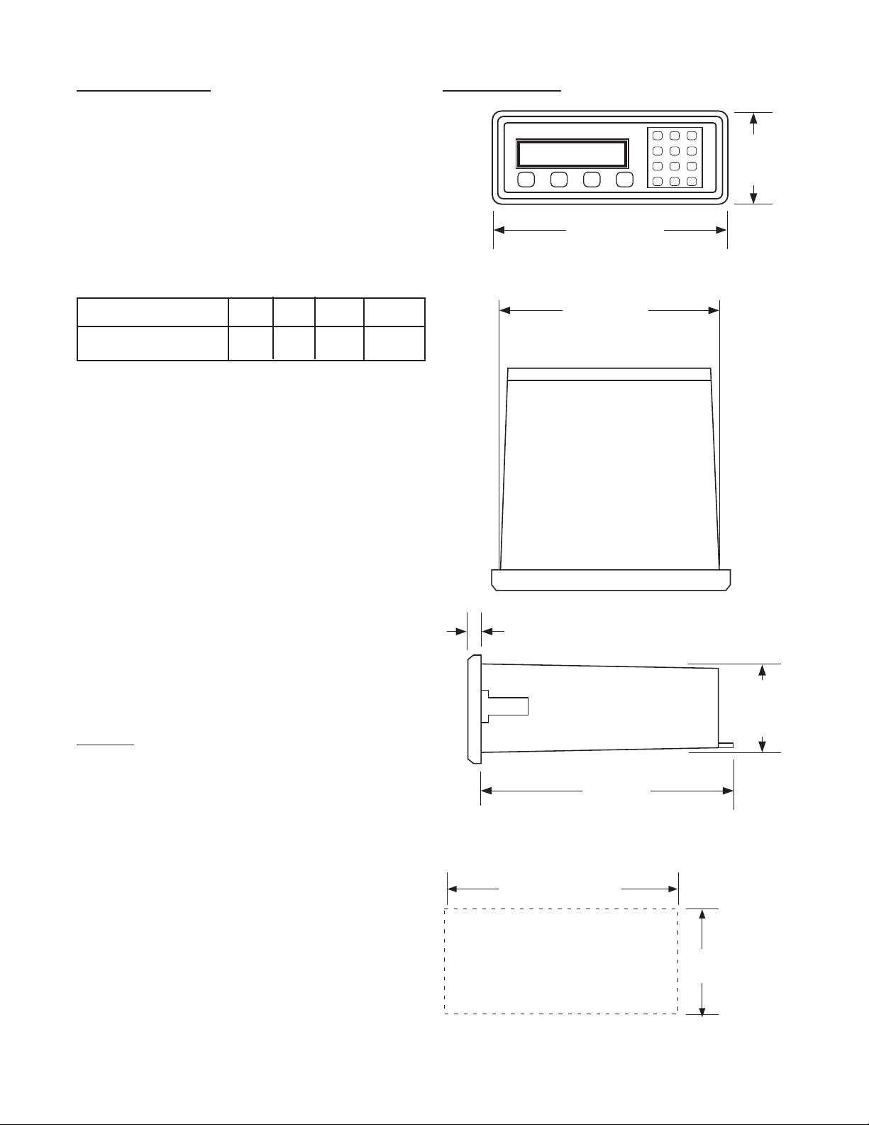
Dimensions:
See Section 1-5, Page 4.
Display:
8 Digit, 0.55” High, 15 Segment, Red Orange,
LED.
Input Power:
A: 110 VAC ± 15% or 12 to 27 VDC
B: 220 VAC ± 15% or 12 to 27 VDC
NOTE: AC Inputs are internally fused with a
160mA slow blow fuse.
Current:
Maximum 280 mA DC or 5.3 VA at rated AC
voltage.
Output Power:
(On AC powered units only): +12 VDC at 100
mA. Separate Isolated 12 VDC at 100 mA to
allow ± 12 VDC or +24 VDC, regulated ± 5%
worst case.
Temperature:
Operating: +32°F (0° C) to +130 ° F (+54° C)
Storage: -40°F (-40° C) to +200 ° F (+93° C)
(Extended operating temperature range
available, consult factory)
Memory:
EEPROM stores all program, display mode
and count data for a minimum of 10 years if
power is lost.
Reset
Front push button: “CLR” resets displayed
number and control output.
Remote Input (Terminal 5): Open or 0 to 1
VDC (low), 3 to 30 VDC (high), 10K ohm input
impedance to ground. Minimum pulse on /
off time 5 msec.
Accuracy over full temperature range:
Analog - Zero error: ±0.175% full scale max.
Overall error: ±0.5% full scale max.
Digital - 100% (within specied voltage
ranges)
Pulse Inputs:
3A: Standard. High impedance pulse input.
Open or 0 to 1 VDC (low), 3 to 30 VDC (high),
10K ohm input impedance. 20 KHz maximum
speed (min. on / off 25 usec).
3B: Same as 3A except 4.7 K ohm pull up re-
sistor to +5 VDC with respect to Terminal 12.
Analog Inputs:
The current or voltage input is converted to a
highly linear 0 to 10 KHz frequency. This fre-
quency can then be scaled by 8 digit K-factors
to display rate or count in the appropriate en-
gineering units.
5A: 4-20 mA; 250 Ω input impedance.
5B: 0-20 mA; 250 Ω input impedance.
5C: 1-5 VDC; 15 KΩ input impedance.
5D: 0-5 VDC; 15 KΩ input impedance.
5E: 0-10 VDC; 15 KΩ input imped-
ance.
6A: Square Law: 4-20 mA; 250 Ω in-
put impedance.
5
1-5 Specications (continued)
Factored Output:
One pulse per each factored count
Sinking (NPN Transistor)
Open Collector sinks 250 mA maximum to 1
volt maximum from 30 VDC maximum
Internal buffer: 9999 pulses
Output speed: user selectable (see table
below)
Speed (Hz) 10 200 2000 20000
Min. on/off (msec) 47.5 2.0 0.2 0.013
Analog output:
(Not available with 4-20 mA, Square Law
input type)
4-20 mA (or 0-20 mA)
Sinking, (NPN transistor), Open Collector
Compliance voltage: 3-24 VDC, non-inductive
Accuracy: ±100 uA worst case
Update Rate: Follows ratemeter
Control Outputs:
SPDT Relays
Contact rating: 10 A 120/240 VAC or 28 VDC.
NPN Transistor Output
Open Collector sinks maximum of 100 mA from
10 VDC when active
Note: 10 VDC is provided at transistor outputs
through the relay coils. If current greater than
2 mA is drawn, the relay will remain energized.
Applying greater than 10 VDC may destroy the
unit. The transistor will sink 100 mA in the “ON”
state with relays installed.
PANEL
CUTOUT
2.50 -0, +0.02
(63.5 -0, +0.5)
7.375 -0, +0.04
(187.3 -0, +1)
7.375
(187.3)
(NOM.)
0.53
(13.5)
6.0
(152.4)
2.48
(63)
(NOM.)
(NOM.)
A B C D
1 2 3
4 5 6
7 8 9
CLR
0
SET
8.17
(207.5)
3.31
(84)
1-6 Dimensions
All Dimensions in inches (mm)

6
Full Size Panel Cutout Template
(copy before using)
SECTION 2 INSTALLATION
2-1 Receipt of Equipment
When the equipment is received, the outside
packing case should be checked for damage
incurred during shipment. If the packing case
is damaged, the local carrier should be notied
at once regarding his liability. A report should
be submitted to the factory.
Carefully remove the equipment from the pack-
ing case and inspect for damaged or missing
parts.
2-2 Return Shipment
Do not return assembly or part with out a Return
Material Authorization. The RMA is obtained by
calling your local distributor.
2-3 Panel Mounting
The controller should be located in an area with
a clean, dry atmosphere which is relatively free
of shock and vibration. The Batcher is installed
in a 7.365” (187 mm) wide by 2.495” (63.4 mm)
high panel cutout. To mount the controller pro-
ceed as follows:
a. Prepare the panel opening.
b. Slip the gasket (provided) over the rear of
the counter case and slide it forward until it
engages the inner surface of the front be-
zel.
c. Install the screws (provided) in the mounting
brackets and insert in the holes located on
both sides of the Batcher.
d. Tighten the screws rmly to attach the coun-
ter bezel to the panel.
2-4 Electrical Connections (Reference Figures
2-1 to 2-3)
All connections are completed at terminal blocks
located at the rear of the case. Make sure all
power is disconnected before making any elec-
trical connections. In cases where cables are
situated in areas with heavy electrical elds,
1-5 Dimensions (continued)
7
2-4 Electrical Connections (continued)
shielding is required for maximum noise im-
munity. One end of the shielding should be
connected to earth ground. Relays or induc-
tive coils connected to or located in the im-
mediate area should be arc suppressed with
appropriate diodes, MOV’s or resistor capaci-
tor networks.
Caution:
An external fuse is required
for DC powered units.
DC Power: Use a 0.5 Amp
Fuse inline with Term. 14
AC units are internally fused.
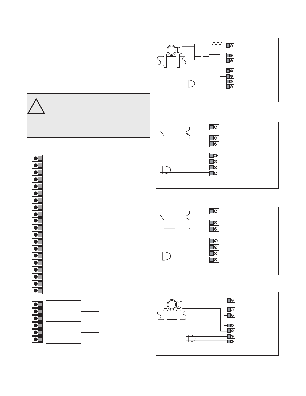
2-5 Wiring Connections and Diagrams
1 - Not Used
2 - Scaled Pulse Output O.C.
3 - Analog Output
4 - Input A (Pulse/Analog)
5 - Remote Stop/Reset Input
6 - Not Used
7 - Not Used
8 - Not Used
9 - Not Used
10 - Remote Start Input
11 - Ground (-DC), Input Common
12 - Ground (-DC), Input Common
13 - +12 Volts Out
14 - DC Power In (12 - 27 VDC)
15 - Isolate -12 Volts
16 - Isolate +12 Volts
17 - AC In
18 - AC In
19-Prewarn Transistor O.C.
20-Preset Transistor O.C.
R1-N.O
R2-N.C. Preset
R3-Common
R4-N.O
R5-N.C. Prewarn
R6-Common
Figure 2-1 Terminal Block Connections
2-5 Wiring Connections and Diagrams
Figure 2-2
Typical Digital Wiring Connections
Figure 2-5
Typical Analog Wiring Connections
FLOWMETER
SHIELD
GROUND
SIGNAL
1
2
3
TB1
AMPLIFIER
TB2
3
2
1
4 - Input A
12 - Ground (-DC)
13 - +12 Volts Out
15 - Isolate -12 Volts
16 - Isolate +12 Volts
17 - AC In
18 - AC In
+24VDC
GROUND
1 10 VA C
60/50 Hz
!
FLOWMETER
ANALOG SIGNAL
4 - Input A
12 - Ground (-DC)
13 - +12 Volts Out
15 - Isolate -12 Volts
16 - Isolate +12 Volts
17 - AC In
18 - AC In
+24VDC
1 10 VA C
60/50 Hz
Figure 2-3
Typical Digital NPN (Input 3B) Wiring
4 - Input A
12 - Ground (-DC)
13 - +12 Volts Out
15 - Isolate -12 Volts
16 - Isolate +12 Volts
17 - AC In
18 - AC In
1 10 VA C
60/50 Hz
Switch
Closure
NPN
Output
Figure 2-4
Typical Digital PNP (Input 3A) Wiring
4 - Input A
12 - Ground (-DC)
13 - +12 Volts Out
15 - Isolate -12 Volts
16 - Isolate +12 Volts
17 - AC In
18 - AC In
1 10 VA C
60/50 Hz
Switch
Closure
PNP
Output
All AC powered BT2 Models are equipped with an internal fuse.
Use KEP part #14039 for replacement
All AC powered BT2 Models are equipped with an internal fuse.
Use KEP part #14039 for replacement
All AC powered BT2 Models are equipped with an internal fuse.
Use KEP part #14039 for replacement
All AC powered BT2 Models are equipped with an internal fuse.
Use KEP part #14039 for replacement

8
3-1 Front Panel Operation
START - Pressing “A”, starts the
process by energizing the PRESET and
PREWARN relays. Press “CLR” to reset
Batch Total before starting new batch.
STOP - Pressing “B”, will temporarily
stop the process by de-energizing the
PRESET and PREWARN relays. Use
START to continue the process from
where it stopped.
RATE/TOTAL -
STD PRE mode
Pressing “C” toggles between rate and
total count displays. The rate display has
an “R” on the left side of the screen.
EZ PRE mode
Pressing “C” toggles between rate, total
count and preset displays in EZ PRE
mode. The rate display has an “R” on
the left side of the screen and the preset
display has a “P” on the left side of the
screen.
MENU - Pressing “D” takes the unit out of
the Run Mode and into the Programming
Mode (See Programming, Page 43 and
45). “D” is also used make to some
programming selections.
ENT - With Total Count showing in
the Run Mode (see “C” key), pressing
“ENT” displays the Grand Total, which
begins ashing on the screen. Press
“ENT” again to return to the Count. In
the Programming Mode, “ENT” is used
to accept a selection (See Programming,
Page 43 and 45).
CLR - When the count total is displayed,
pressing “CLR” will reset the counter to 0
or to Preset A depending on how it was
programmed. When the Grand Total is
displayed, pressing “CLR” will reset it to
0. When the Preset or Program Mode
values are displayed, pressing “CLR” will
reset them to 0, so that new values can
be entered.
A
B
C
D
ENT
CLR
Weighted Averaging
Version 8.7 of the batcher software includes
weighted averaging of the rate display. Weighted
averaging is not available on units with 16 Point
Linearization.
Weighted averaging can be used to create a more
stable display when the rate input is uctuating.
A weight, “W”, from 00 to 99 is applied to the old
rate data before the new rate data is sent to the
display. The following equation is used:
W = Weight (00-99)
If a weight of 00 is used, the new rate data will
go directly to the display without being averaged.
If a number other than 00 is entered for the
weight, then the new data will be averaged with
the old data before being sent to the display.
Higher weight numbers will create a more stable
rate display. Small rate changes will be more
noticeable when lower weight numbers are used.
Programming Weighted Averaging
1. In the Program Mode, got to the RATE sub menu
and program the K-FACTOR, the WINDOW, and
the SIG FIG parameters.
2. When the display shows WEIGHTXX (XX
represents the current WEIGHT value), either
accept the current value and return to the Run
Mode by pressing “ENT” or clear the current value
by pressing “CLR”.
3. If the current value was cleared, the display
shows WEIGHT00. Using the keypad, enter a
new WEIGHT value from 00 to 99. Press “ENT” to
accept the new value and return to the Run Mode.
(Old Data x W + New Data)
(W + 1)
Rate Display =
Remote Start, Stop, and Reset
A 4 to 30 VDC positive pulse will activate these
inputs. Remote Start, Stop, and Reset is not
available on units ordered with the Control Input
option 7A (4-20 mA In, 4-20 mA Out).
START (Pin 10): When activated, the unit will
START as described in Front Panel Operation.
STOP/RESET (Pin 5): When activated, the unit will
STOP (If the unit is started and the batch is not
complete). A second pulse to pin 5 will reset the
counter (When the unit is stopped or when the
batch is complete). If pin 5 is held high (4 to 30
VDC), the display will ash “STOPPED” and any
start inputs will be inhibited.
STOP
D
START
RATE/TOTAL
MENU
CBA
ENT
0
7
4
1
2
3
6
5
8
9
CLR

9
3-2 VER 8.8 Programming
Overview:
This Section of the manual provides an outline of
programming procedures for the batcher software
version 8.7. Detailed descriptions and programming
instructions for this unit are available in previous
sections of this manual. Page number references
are included to help you nd related information in
this manual.
Programming Procedures:
Enter Program Mode - Press the MENU button,
“D”, in the Run Mode.
Choosing a Sub Menu - Once in the Program
Mode, continue pressing the “D” button until the
desired Sub Menu is displayed. Press “ENT” to
enter the selected Sub Menu.
Making a Selection - An arrow, “↓”, appearing over
only the “D” button indicates that “D” is used to
change the selection. When an arrow appears
over “B” and “D”, one must be selected.
Entering a Value - The keypad is used to enter a
number. Use the “D” button to enter a decimal.
(Ex: 34.5 would be entered by pressing “3”, “4”,
“D”, and “5”)
Accept a Value or Selection - Press “ENT” to ac-
cept the value and go to next step.
Exit Program Mode - Program or skip each step
of one of the menus to return to the Run Mode.
Pressing “ENT” allows a step to be skipped with-
out changing its value.
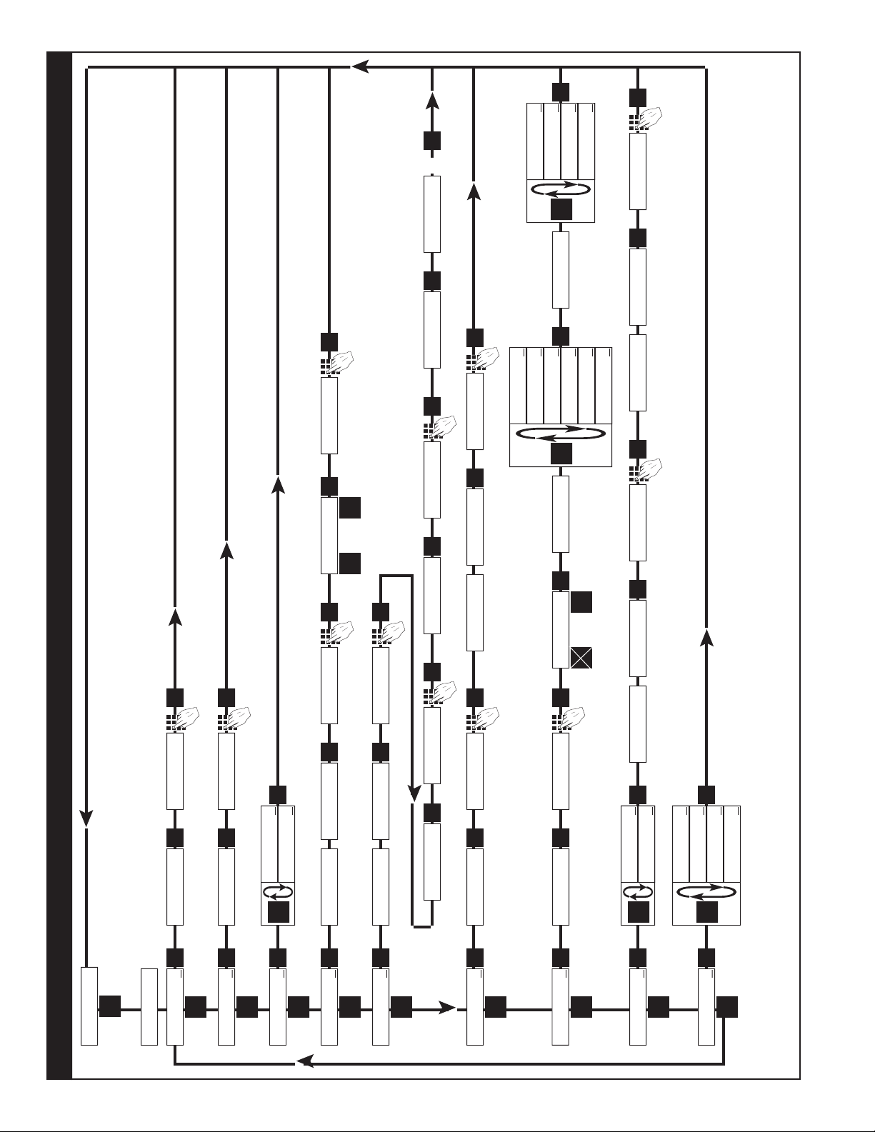
Key to Programming Flow Chart:
■
Display - This box represents the unit’s dis-
play. In the Run Mode, the ow rate, the batch
total, or the grand total will be displayed.
XX Current Value - The number that is currently
programmed for that step. It must be cleared
(CLR button) before entering a new value.
00 No Value - Indicates that programmed value
for that step has been cleared, and a new
number may be entered.
Keypad - Use the front panel keypad to enter
a value or select a decimal point location for
this step.
3-3 VER 8.8 K-Factor Programming
(See Programming Flow Chart, Page 10)
The average sensor K-Factor is usually provided in
pulses per unit volume, and will have to be modied
before entering it into the instrument. On most ow-
meters, the average sensor K-Factor is stamped
on the nameplate or provided on its documenta-
tion. (see section 7 for Calculating K-Factors, for a
complete example)
Count K-Factor:
The Count K-Factor must be modied to allow for
the decimal point location chosen in the ”DEC LOC“
step.
DPF - The Decimal Point Factor is a divider to com-
pensate for the displayed decimal point.
DPF Table
DPF Decimal
1 XXXXXX.
10 XXXXX.X
100 XXXX.XX
1000 XXX.XXX
10000 XX.XXXX
100000 X.XXXXX
Rate K-Factor:
The Rate K-Factor must be determined to dis-
play the rate in the desired time unit. The oating
decimal point displayed by the Rate Meter oats
according to the signicant gure setting used in
the SIG FIG step.
Where:
TF - The Time Factor is a divider to adjust the
time units that the Rate Meter shows.
TF Table
TF Time Units Rate Display
1 Seconds Units per Second
60 Minutes Units per Minute
3600 Hours Units per Hour
86400 Days Units per Day
(For information on entering a K-Factor on a unit
with 16 Point Linearization, see 16 Point Linear-
ization Notes, page 11)
Sensor K-Factor
TF
= Rate K-Factor
Sensor K-Factor
DPF
= Count K-Factor
10
Software Version 8.8 Programming Flow Chart
ENT
D
RATE
↓
D
ENT
K-FACTO R
XXXX
CLR
WINDOWXX
CLR
S I GF I G X X
CLR
WE IGHTXX
LOCKOUT
↓
ENT
D
SECUR XX
CLR
CODE
XXXX
CLR
UNIT X X
CLR
ALG OU T
↓
OUTFREQ
↓
ENT
D
ENT
D
D
ANLG RT
↓
ANLG CT
↓
ENT
SE T LO W
XXXX
CLR
SET HIGH
D
2000
↓
200
↓
ENT
20000
↓
10
↓
0
ENT
WINDOW00
ENT
S I G F I G 0 0
ENT
SECUR 00
ENT
0
UNIT 00
ENT
0
ENT
PL↓ SE R↓
ENT
D
B
⇒
BAUDRATE
D
1200
↓
2400
↓
600
↓
300
↓
4800
↓
9600
↓
COUNT
↓
ENT
D
K-FACTO R
XXXX
CLR
R0↓ SP↓
ENT
D
B
⇔
D.E.C. . .L.O.C.
8 7 6 54 3 2 1
ENT
0
ENT
PRESET
↓
ENT
D
XXXX
CLR
PREWARN
↓
D
XXXX
CLR
ENT
PRE TYP
↓
ENT
D
D
EZ PR E
↓
STD PRE
↓
ENT
0
ENT
0
ENT
MENU
D
Run Mode
◊ - On a Standard unit (Without 16 Point Linearization), the Count and/or the Rate must be programmed for basic operation.
§ - Sub menu will always appear, but feature may not be included in the unit. (Check Model Number).
Page
2, 24
§ Page
2, 23
§ Page 2, 21
Page 2, 19
◊ Page 1, 17
◊ Page 2, 15
Page 15
Page 1, 14
Page 1, 14
OUTCARD
↓
CLR
XXXX
CLR
WEIGHT0 0
ENT
ENT
0
ENT
ENT
PARITY
D
ODD
↓
MARK
↓
ENT
EVEN
↓
SPA CE
↓

11
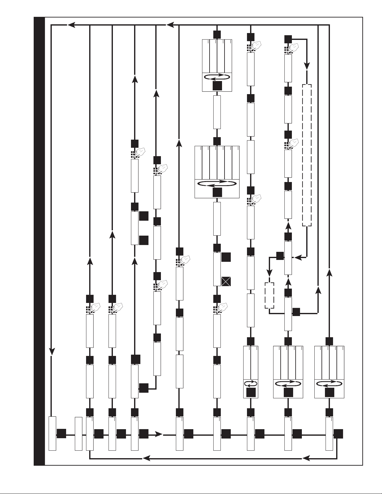
3-5 VER 12.0 Programming
(Unit with 16 Point Linearization)
Overview:
This Section of the manual provides an outline
of programming procedures for the software ver-
sion 12.0. Detailed descriptions and programming
instructions for this unit are available in the following
sections of this manual. Page number references
are included to help you nd related information in
this manual.
Programming Procedures:
Enter Program Mode - Press the MENU button,
“D”, in the Run Mode.
Choosing a Sub Menu - Once in the Program
Mode, continue pressing the “D” button until the
desired Sub Menu is displayed. Press “ENT” to
enter the selected Sub Menu.
Making a Selection - An arrow, “↓”, appearing over
only the “D” button indicates that “D” is used to
change the selection. When an arrow appears
over “B” and “D”, one must be selected.
Entering a Value - The keypad is used to enter a
number. Use the “D” button to enter a decimal.
(Ex: 34.5 would be entered by pressing “3”, “4”,
“D”, and “5”)
Accept a Value or Selection - Press “ENT” to ac-
cept the value and go to next step.
Exit Program Mode - Program or skip each step
of one of the menus to return to the Run Mode.
Pressing “ENT” allows a step to be skipped with-
out changing its value. (Note: “B” or “D” must be
pressed on the rst step in the DEV TYP menu)
Key to Programming Flow Chart:
■
Display - This box represents the unit’s dis-
play. In the Run Mode, the ow rate, the batch
total, or the grand total will be displayed.
XX Current Value - The number that is currently
programmed for that step. It must be cleared
(CLR button) before entering a new value.
00 No Value - Indicates that programmed value
for that step has been cleared, and a new
number may be entered.
Keypad - Use the front panel keypad to enter
a value or select a decimal point location for
this step.
3-6 VER 12.0 16 Point Linearization Notes
(See Programming Flow Chart, Page 12)
A K-Factor and a Frequency must be entered for at
least three points on a unit with Linearization.
Linearization K-Factor: The K-Factor for each
Linearization point must be modied to allow for the
display decimal point location chosen in the “DEC
LOC” step of the “DEV TYP” menu. Modify each
K-Factor using the following equation:
DPF - The Decimal Point Factor is a divider to
compensate for the displayed decimal point.
DPF Table
Desired Total
Decimal Location: DPF
XXXXXX. 1
XXXXX.X 10
XXXX.XX 100
XXX.XXX 1000
XX.XXXX 10000
X.XXXXX 100000
Example: for X.X, DPF = 10
Calculating K-Factors and Frequencies: If a
Linearization table is not available, the K-Factor
and the frequency for each point can be calculated
using the Test Mode on the unit. Refer to Section
7-3.2, Test Mode Operation and K-Factor
Calculation, on page 37.
Entering K-Factors and Frequencies: Refer to
Section 7-3, Calculating 16 Point K-Factors, on
page 37 and the programming step listing on page
25.
K-Factor
DPF
= Linearization K-Factor
12
OUTCARD
↓
ENT
D
LOCKOUT
↓
ENT
D
UNIT X X
CLR
ALG OU T
↓
OUTFREQ
↓
ENT
D
ENT
D
D
ANLG RT
↓
ANLG CT
↓
ENT
SE T LO W
XXXX
CLR
SET HIGH
XXXX
CLR
D
2000
↓
200
↓
ENT
20000
↓
10
↓
UNIT 00
ENT
0
ENT
0
ENT
PL↓ SE R↓
ENT
D
B
BAUDRATE
D
1200
↓
2400
↓
ENT
600
↓
300
↓
4800
↓
9600
↓
PARITY
D
ODD
↓
MARK
↓
ENT
EVEN
↓
SPA CE
↓
PRESET
↓
ENT
D
XXXX
CLR
PREWARN
↓
D
XXXX
CLR
ENT
DEV TYP
↓
ENT
D
0
ENT
0
ENT
MENU
D
Run Mode
Software Version 12.0 16 Point Linearization Programming Flow Chart
RT↓ CNT↓
R0↓ SP↓
ENT
D
B
D.E.C. . .L.O.C.
8 7 6 54 3 2 1
ENT
D
B
WINDOWXX
CLR
S I GF I G X X
CLR
WINDOW00
ENT
S I G F I G 0 0
ENT
16 POINT
↓
ENT
D
D
MINUTE S
↓
HOURS
↓
ENT
SECONDS
↓
T EST
↓
POINT 00
1
POINT 01
ENT
F XX
CLR
F 00
ENT
K XX
CLR
K 00
ENT
ENT
CLR
To Exit
Increment to next point (Ex. POINT 02, POINT 03, Etc.
◊ - At least three points in the 16 Point Linearization sub menu must be programmed for basic operations.
Enter a Point # of “0” at any point to exit the 16 Point settupeep all data entered up to that point.
§ - Sub menu will always appear, but feature may not be included in the unit. (Check Model Number).
Do not use PL. Select SER.
CODE
XXXX
CLR
0
ENT
⇒
⇔
3-7
 Loading...