

Page 1
RTP
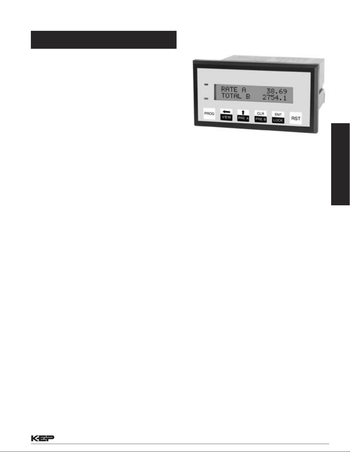
Features
• Two pulse and three control inputs
• Displays: A Rate, A Total, B Rate, B Total, A+B
Rate, A+B Total, A-B Rate, A-B Total, Grand
Total
• Separate Scaling Factors For A & B Inputs
Two Separate Ratemeters, Totalizers
With Two Line LCD Display
• Two relay outputs with LED Indication
• RS232/ RS485 port for serial communication
and printing
• Security lockout
• 4-20 mA output (optional)
DESCRIPTION:
The RTP is a presettable Ratemeter and Totalizer from two
pulse inputs. It can show rate and total at the same time on the
2 X 16 backlit LCD display. Both inputs can have up to 16 point
linearizing k factors. The unit can be connected in a network for
Data Acquisition.
SPECIFICATIONS:
INPUT POWER: AC: 100 to 260 VAC; 6.5 VA
DC: +24 VDC ; 250 mA max.
THRESHOLD: High: 4-24 VDC; Low: < 1Vdc or open
INPUT A: Count Input, 5 kHz max.
INPUT B: Count Input, 5 kHz max.
INPUT C: Control Input
INPUT D: Control Input
INPUT E: Control Input (Not Used with RS485
NOTE: AC powered units have isolated inputs. DC units share
-DC with input common.
OUTPUT POWER: +20VDC @50 mA (unreg), +/- 15%
DISPLAY: 2 lines of 16 characters, backlit LCD
(character size: 2.95mm x 5.55mm)
DISPLAY RESOLUTION: 6 Digit Total, 6 Digit Rate
BEZEL: NEMA 4/IP65 rated membrane keypad
INDICATORS: Two LED’s to indicate control output status.
(Red = Output A, Green = Output B)
MEMORY: NVRAM retains data on power failure
TEMPERATURE: Operating : 0 to 50 degrees C
Storage : -40 to 90 degrees C
HUMIDITY: 10% to 90% ( Non condensing )
SIZE: Bezel: 103mm X 55 mm; Depth:97 mm
PANEL CUTOUT: 92 mm X 45 mm (1/8 DIN size cutout )
IMMUNITY TO ESD: Level 3 per IEC1000-4-2
IMMUNITY TO TRANSIENTS: Level 3 per IEC1000-4-4
RADIATED SUSCEPTIBILITY: Level 3 per IEC1000-4-3
EMISSIONS: EN55011 CISPR A
RATEMETERS/TOTALIZERS
Flow Instruments
• NVRAM to retain data on power failure
• NEMA 4 / IP65 Front Panel
PULSE INPUTS
The RTP can accept two pulse inputs ( A&B ). It computes rate
and total of A, B, A+B and A-B. For both inputs the user can
define up to 16 points of “k” factors. This allows linearization of
the displayed rate, which is useful in improving the accuracy of
the flowmeter.
The rate is computed within 300 ms per input. To stabilize the
rate display, the user can select normalizing factor, which allows
weighted average to be shown. Moreover, for rate displays, a
time delay of up to 25 seconds can also be selected.
CONTROL INPUTS
The RTP has three Control Inputs, i.e. Input C, Input D and Input E
(Only C & D with RS485 option). Each input can be configured to
start/stop each counter or reset each counter and Control Output.
These inputs can also perform different control actions like printing
on serial port, lock unit and freeze display.
RESET OPTIONS
The entire unit, i.e. all counters and control outputs, or Counter A,
Counter B, Counter A+B, Counter A-B, Control O/P A and Control
O/P B can be individually programmed to be reset on pressing the
front panel RST key and also by a positive edge signal to any of
the Control I/Ps C, D and E.
SERIAL COMMUNICATION
The serial strobed port can be used for serial printing of Total or
Rate data with descriptors. The unit can also communicate with
a master device through a Modbus-RTU protocol. The data given
for each parameter is in IEEE float format comprising of 2 words.
The unit can be connected in a network. Order Option 1 is RS-232
level format; Order Option 2 is RS-422/485 level format.
CONTROL OUTPUTS
The RTP has the following Control Outputs:
RELAY / O.C.: 2 N.O. relays of 5 A and 250 V OR
2 Open Collector Outputs;
100 mA maximum.
Kessler-Ellis Products • 800-631-2165 F-16 • Flow Instruments • Page 65
Page 2
PROG
VIEW
PRE A
LOCK
RST
PRE B
CLR
ENT
ANALOG OUTPUT
12345
6789
1 2 3 4 5 6 7 8 9 10 11 12 13 14 15 16
12345
6789
17 18
Type: 4-20 mA output.
Accuracy: ± 50µA worst case.
This Analog O/P can be programmed to track any parameter.
Reverse tracking O/P is also available.
PRESETS The unit supports five counters, i.e. Counter A, Counter
B, Counter A+B, Counter A-B and Grand Total. The counters can
either be reset to zero or disabled. Relays can be activated by any
of the Total or Rate values. If a Total preset activates the relay,
the user can select an output duration of 0.1 to 99.9 seconds with
instant auto reset to “0”. A 00.0 duration keeps the relay activated
until externally reset. If both presets are assigned to same counter,
with Relay A duration set to 00.0 and Preset A lower than Preset B,
Relay A pulls in at Preset A and drops out when Preset B (having
a duration other than 00.0) pulls in. Counter recycles immediately,
and Relay B stays activated for the selected duration.
If activated by rate, the relay pulls in at High Preset or above and
remains on until rate falls below Low Preset.
LOCKOUT The unit program and presets can be protected with a
lock code to prevent unauthorized front panel changes. This code
can be assigned with a maximum of 4 digits and is user selectable.
It can be entered through front panel LOCK key or by configuring
any of the Control I/Ps to “Lock unit”. Alternate entry of the lock
code or pulses to that I/P will lock or unlock the unit.
Flow Instruments
RATEMETERS/TOTALIZERS
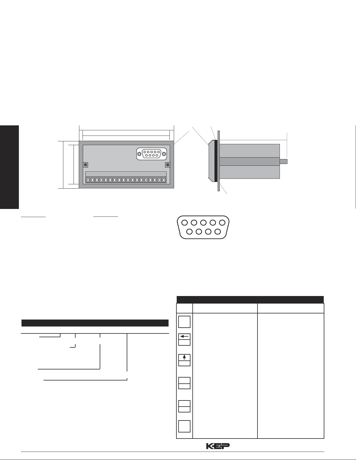
Terminal Designations:
AC Power
1 • AC1 100 TO 260 VAC
2 • AC2 100 TO 260 VAC
3 • RELAY A (N.O.)
4 • COMMON
5 • RELAY A (N.C.)
6 • RELAY B (N.O.)
7 • COMMON
8 • RELAY B (N.C.)
9 • (+) 20VDC OUT (50mA)
10 • (–) 20VDC OUT (50mA)
11 • ANALOG O/P (+)
12 • ANALOG O/P (–)
13 • CTRL I/P E
14 • CTRL I/P D
15 • CTRL I/P C
16 • PULSE I/P B
17 • PULSE I/P A
18 • INPUT GND
1.7” (45mm)
2.17” (55mm)
4.05” (103mm)
3.62” (92mm)
RS-232 Port
DC Power
1 • + DC INPUT (24VDC ± 10%)
2 • – DC INPUT (24VDC ± 10%)
3 • RELAY A (N.O.)
4 • COMMON
5 • RELAY A (N.C.)
6 • RELAY B (N.O.)
7 • COMMON
8 • RELAY B (N.C.)
9 • (+) 20VDC OUT (50mA)
10 • (–) 20VDC OUT (50mA)
11 • ANALOG O/P (+)
12 • ANALOG O/P (–)
13 • CTRL I/P E
14 • CTRL I/P D
15 • CTRL I/P C
16 • PULSE I/P B
17 • PULSE I/P A
18 • INPUT GND
Bezel
Gasket
3.82” (97mm)
Panel
Communication Port Terminal Designations:
RS-232 Port:
(DB9 Female)
6 - NC
7 - CMOS TXD
8 - TX
9 - RX
RS-485 Port:
(DB9 Female)
1 - TX+
2 - TXD
3 - RXD
4 - RX+
5 - GND
KEYPAD FUNCTIONS
KEY
Run Mode
Program Mode
Ordering Information
Example: RTP A 3 1
Series:
RTP= Pulse Input Ratemeter/Totalizer
Enter The Programming
Mode
VIEW key scrolls through the
selected viewing parameters
Toggles between menus
Left key shifts digits in
number entry/characters in
message mode
Operating Voltage:
A= 110 VAC ± 15%
B= 220 VAC ± 15%
*C= 24 VDC
Input:
3= Standard, 4-30 VDC simultaneous inputs
Options:
1= RS-232, 3 Control Inputs (not available with RS-485)
*2= RS-485, 2 Control Inputs (not available with RS-232)
A= 4-20 mA Out (Can be ordered with options 1 or 2)
* Special Order
Accessories
NEMA 4X wall mount enclosure available, see NEMA-1/8DIN
XHV 7/4 Explosion Proof Housing available, see XHV7/4
Serial printer available, see P1000, P295
Ethernet Port Server available, see IEPS
RS-422/485 to RS-232 Communication Adaptor available, see CA285
Page 66 • Flow Instruments • F-16 Kessler-Ellis Products • 800-631-2165
PRE A key allows Preset A
to be changed if unit is not
locked
PRE B key allows Preset B
to be changed if unit is not
locked
Lock Key allows the entry
of a lock code to lock/unlock
the unit
RST Key resets counters
(with/without confirmation
Up key increments digits/
characters
CLR key clears the numeric
field
ENT key saves changes and
steps to next menu
Unit comes out of
programming at any level
 Loading...