

Page 1

Process Monitor
PMT-555
Installation and Operating Manual
KESSLER-ELLIS PRODUCTS
10 Industrial Way East
Eatontown, NJ 07724
800-631-2165 • 732-935-1320
Fax: 732-935-9344
with Totalizer
For Analog Inputs
99909 12/02/04
Page 2

Page 3
Page 4
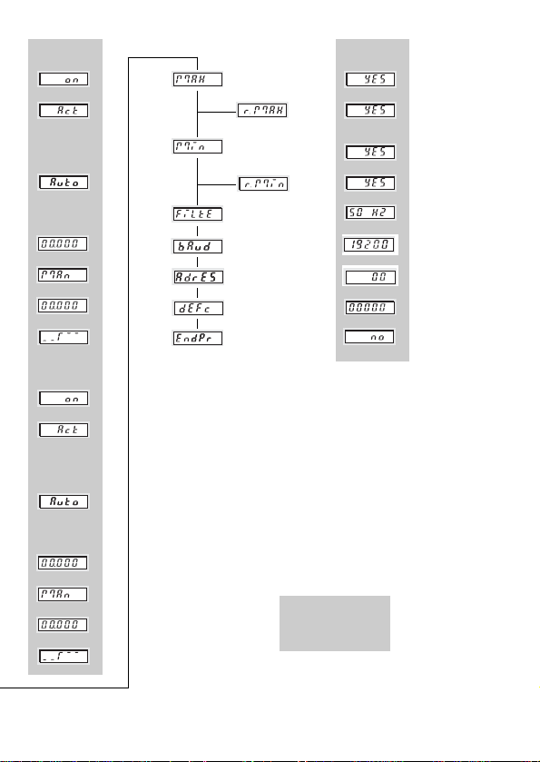
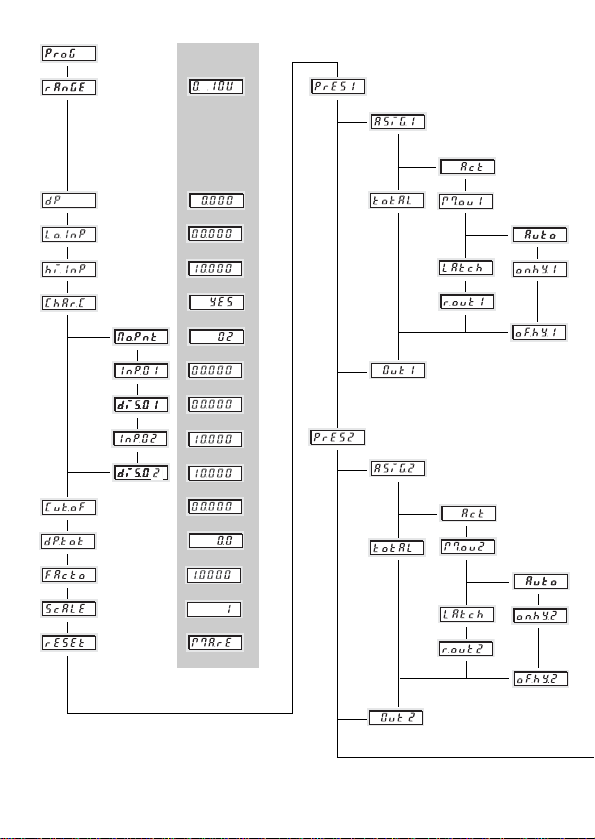
Values in gray are
factory preset
Page 5

Page 2
11 SSaaffeettyy iinnssttrruuccttiioonnss aanndd wwaarrnniinnggss
................................................................................. 3
1.1 Use according to the intended purpose ........................................................ 4
22.. TTeecchhnniiccaall DDaattaa
2.1 Miscellaneous Data ......................................................................................................... 5
2.2 Electrical Data .................................................................................................................. 5
2.2.1 Power Supply ..................................................................................................... 5
2.2.2 Inputs ................................................................................................................... 5
2.2.3 Outputs
2.2.4 Interfaces ............................................................................................................ 6
2.3 Mechanical Data .............................................................................................................. 7
2.4 Environmental conditions ................................................................................................ 7
2.5 Delivery .............................................................................................................................. 7
2.6 Order Code ........................................................................................................................ 7
33.. MMoouunnttiinngg
........................................................................................................................... 8
44.. EElleeccttrriiccaall CCoonnnneeccttiioonnss
4.1 Measuring inputs ............................................................................................................. 8
4.2 Control Inputs and Auxiliary Power Supply ................................................................. 9
4.3 Power Supply and Alarm Outputs ................................................................................ 9
4.4 Interfaces .......................................................................................................................... 9
55.. PPaarraammeetteerr SSeettuupp
5.1 Parameter mode ..............................................................................................................10
5.2 Parameter input for Instantaneous Value ....................................................................11
5.2.1 Select range for the input signal ....................................................................11
5.2.2 Set the decimal point for the actual value ....................................................11
5.2.3 Change the range limits ....................................................................................12
5.2.4 Scaling Slope ......................................................................................................13
5.3 Setting the Scaling Slope
5.3.1 Enter the number of Scaling points ................................................................14
5.3.2 Define first Scaling point ..................................................................................15
5.3.3 Define second Scaling point ...........................................................................15
5.3.4 Define further Scaling points ...........................................................................15
5.4 Totalizer
5.4.1 Setting the Input Threshold for the Totalizer ................................................15
5.4.2 Totalizer Setup ...................................................................................................16
5.4.2.1 Setting the decimal point for the totalizer ..................................18
5.4.2.2 Overall scaling for the total value .................................................18
5.4.3 Resetting the Total value ..................................................................................19
5.5 Alarms/Alarm Outputs
5.5.1 Alarm 1/Output 1 ................................................................................................20
5.5.1.1 Alarm 1 off/on ..................................................................................20
5.5.1.2 Select threshold 1 ..........................................................................20
5.5.1.3 Select mode for output threshold 1 ..............................................20
5.5.1.4 Hysteresis for threshold 1 ..............................................................21
5.5.1.5 Reset Latch signal at output 1 ......................................................22
5.5.1.6 Select signal form for output threshold 1 ...................................23
Page 6

Page 3
5.5.2 Alarms 2/Output 2 ............................................................................................. 23
5.5.2.1 Alarm 2 off/on .................................................................................. 23
5.5.2.2 Select threshold 2 ...........................................................................23
5.5.2.3 Select mode for output threshold 2 ............................................. 23
5.5.2.4 Reset Latch signal at output 2 ......................................................24
5.5.2.5 Reset Latch signal at output 2 ...................................................... 24
5.5.2.6 Select signal form for output threshold 2 ...................................25
5.6 MIN/MAX value acquisition ........................................................................................... 25
5.6.1 Maximum value monitoring .................................................................................. 25
5.6.1.1 Resetting the maximum value ......................................................25
5.6.2 Minimum value monitoring ..............................................................................25
5.6.2.1 Resetting the minimum value .................................................... 26
5.6.3 Effect of Overflow/Underflow for MIN/MAX value ..................................... 26
5.7 Mains Hum Filter .............................................................................................................26
5.8 Interface ............................................................................................................................26
5.8.1 Baud rate ............................................................................................................ 27
5.8.2 Address ...............................................................................................................27
5.9 Setting default value .......................................................................................................27
5.10 End of setup ...................................................................................................................... 27
5.11 Check/alter parameters ................................................................................................. 28
66.. OOppeerraattiioonn
.......................................................................................................................... 28
6.1 Switching over the display during operation ............................................................. 29
6.2 Setting the limits during operation ...............................................................................30
6.3 Resetting the MIN/MAX value ......................................................................................30
6.4 Resetting the Totalizer ....................................................................................................32
6.5 Display Hold ..................................................................................................................... 32
Page 7

Page 4
Only use this display
– in a way according to its intended
purpose
– if its technical condition is perfect
– adhering to the operating
instructions and the general
safety instructions.
The digital display may be used only as a
panel-mounted device. Applications of this
product may be found in industrial
processes and controls, in manufacturing
lines for the metal, wood, plastics, paper,
glass, textile and other processing industries.
Over-voltages at the terminals of the digital
display must be kept within the limits in
Category II
If the digital display is used to monitor
machines or processes in which, in case of
a failure of the device or an error made by
the operator, there might be risks of
damaging the machine or causing accidents to the operators, it is your
responsibility to take appropriate safety
measures.
11..11 UUssee aaccccoorrddiinngg ttoo tthhee iinntteennddeedd ppuurrppoossee
11 SSaaffeettyy iinnssttrruuccttiioonnss aanndd wwaarrnniinnggss
1. Before carrying out any installation or
maintenance work, make sure that the
power supply of the digital display is
switched off.
2. Only use this digital display in a way according to its intended purpose.
3. If its technical condition is perfect.
4. Adhering to the operating instructions
and the general safety instructions.
5. Adhere to country or user specific regulations.
6. The digital display is not intended for use
in areas with risks of explosion and in
the branches excluded by the standard
EN 61010 Part 1.
7. The digital display shall only operated if
it has been correctly mounted in a
panel, in accordance with the chapter
“Main technical features”.
!
Page 8

Page 5
22.. TTeecchhnniiccaall DDaattaa
22..11 MMiisscceellllaanneeoouuss DDaattaa
Display 5 digit red LED
14.2 mm high
Display range –19999 ... 99999, with leading zeros suppression
Out of Range Indication Under-range uuuuu / Over-range ooooo
Data storage EEPROM, 1 Million storage cycles or 10 Years
Test voltages
EN 61010 Part 1 ; overvoltage category 2,
level 2
EMC Interference emissions EN 50081-2 / EN 55011 Class B
Interference resistance EN 61000-6-2
22..22 EElleeccttrriiccaall DDaattaa
22..22..11 PPoowweerr ssuuppppllyy
AC power supply 90 ... 260 V AC/max. 6 VA
external fuse 100 mA/T
DC power supply 10 ... 30 V DC, max. 2 W,
galvanically isolated with inverse polarity protection
external fuse 250 mA/T
Mains Hum Filter digital filter 50 Hz or 60 Hz, programmable
22..22..22 IInnppuuttss
MMeeaassuurreemmeenntt rraannggeess
Current input (DC)
Ranges 0 ... 20 mA, 4 ... 20 mA
Resolution 2 µA
Voltage drop max. 2 V bei 20 mA
Max. current 50 mA
Voltage input(DC)
Ranges 0 ... 10 V, 2 ... 10 V, ±10 V
Resolution 1 mV
Input resitance > 2 MΩ
Max. voltage ± 30 V
A/D converter Dual-Slope
Measuring speed approx. 2 measurements/s
Linearity < 0,1% ±1 Digit for the whole measuring range at an
ambient temperature of 20°C
Zero calibration automatic
Temperature drift 100 ppm/K
Page 9

Page 6
DDiiggiittaall iinnppuuttss
Input MPI* Function of the inputs depending on set up
1. Function Display-Hold to stop the instantaneous value
2. Function Reset Reset the alarm value
Alarm Latch
3. Function Reset-Totalizer Resetting the Totalizer
*MPI: Multi Purpose Input
Input KEY Keypad lock-out of alarm settings
Switching level logical 0 0 ... 2 V DC
logical 1 4 ... 30 V DC
Min. pulse duration > 5 ms
Input MPI and Input KEY are galvanically isolated
22..22..33 OOuuttppuuttss
AAllaarrmm 11//AAllaarrmm oouuttppuutt 22
RReellaayy oouuttppuutt
with volt-free changeover contacts
can be setup as normally closed or normally open
Switching voltage 250 V AC/300 V DC
Switching current max. 3 A AC/DC, min. 30 mA DC
Switching power 2000 VA / 50 Ω
oorr
NPN-
ooppttooccoouupplleerr
with open collector and open emitter
Switching power 30 V DC/15 mA
U
CEsat at Ic = 15 mA max. 2.0 V DC
U
CEsat at Ic = 5 mA max. 0.4 V DC
AAuuxxiilliiaarryy ppoowweerr ssuuppppllyy oouuttppuutt ffoorr mmeeaassuurriinngg ttrraannssdduucceerr//sseennssoorr
AACC
models voltage output 10 V DC ±2%, 30 mA
and
voltage output 24 V DC ±15%, 50 mA
DDCC
models only voltage output 10 V DC ±2%, 30 mA
The auxiliary power supply is galvanically isolated from the inputs, outputs and
the interface.
22..22..44 IInntteerrffaaccee
Available options RS232, RS485, RS422
Baud rate 600, 1200, 2400, 4800, 9600, 19200 programmable
Address 00 ... 99 programmable
Data format 8 Data bit, no parity, 1 stop bit
Character format advanced ASCII character format of
IBM-PC without graphic characters
The interface is galvanically isolated from the inputs, outputs and auxiliary voltage.
Page 10

Page 7
22..33 MMeecchhaanniiccaall DDaattaa
Housing Housing for control panel 96 x 48 mm according to
DIN 43 700, RAL 7021
Dimensions (W x H x D) 96 x 48 x 90 mm
Panel cut-out (B x H) 92
+0,8
x 45
+0,6
mm
Mounting depth approx. 83 mm
Weight approx. 220 g
Protection IP 65 (on the front side)
CCoonnnneeccttiioonnss
Power supply and output: 1 x screw terminal, 8-pole, RM 5.08
Measurement and control input: 1 x screw terminal, 11-pole, RM 3.81
Interfaces: (*) 1 x screw terminal, 5-pole, RM 3.81
CClleeaanniinngg::
The front of the unit is only to be cleaned
with a soft wet (water !) cloth.
22..44 EEnnvviirroonnmmeennttaall CCoonnddiittiioonnss
Ambient temperature –10°C ... +50°C
Storage temperature –20°C ... +70°C
Climatic stability relative humidity < 75%, without condensation
22..55 DDeelliivveerryy iinncclluuddss::
Process display
Screw terminal, 8-pole, RM 5.08
Screw terminal, 11-pole, RM 3.81
Screw terminal, 5-pole, RM 3.81(*)
Clamping bracket
Gasket
Multilingual operating instructions
1 set of self-adhesive symbols
* only with the interface option
22..66 OOrrddeerr CCooddee
PMT555.01 0 00
Interface
00 = without interface
05 = RS232
06 = RS422
07 = RS485
Power supply
0 = 90 .. 260 V AC
3 = 10 .. 30 V DC
Page 11
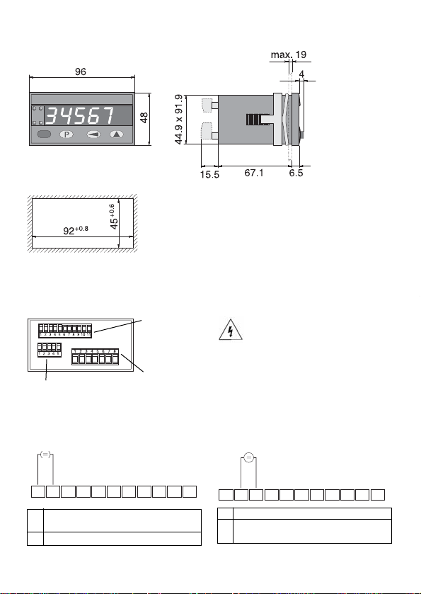
44.. EElleeccttrriiccaall ccoonnnneeccttiioonnss
View of rear of unit
WWaarrnniinngg::
for 90 ... 260 V AC version. Please apply the power supply after the complete installation.
Danger of Death! Please check
unit label before applying the power
supply.
Page 8
33.. MMoouunnttiinngg
Panel cut out
Measuring- and
control inputs
as well as auxiliary signals
Power supply
and limit outputs
Interface
44..11 MMeeaassuurriinngg IInnppuuttss
2 GND1 (Analogue)
3 Voltage input (U)
0 ... 10 V, 2 ... 10 V, -10 ... +10 V
1 Current input (I)
0 ... 20 mA / 4 ... 20 mA
2 GND1 (Analogue)
Current input Voltage input
X2
X1
X3
X2
X2
-
+
1
2
5
3
4
678910
11
1
-
+
5
3
2
678910
4
11
Page 12

Page 9
9 GND3 (for Uout)
10 Uout +10 V/30 mA
11 Uout +24 V/50 mA only for power
supply 90 ... 260 V AC
8 MP-Input "Reset-Alarm-Latch/
Display-Hold/Reset Totalizer"
7 GND2 (KEY/MPI)
6 Keypad lock-out “Key”
44..22 CCoonnttrrooll iinnppuuttss aanndd aauuxxiilliiaarryy ppoowweerr ssuuppppllyy ((UU
oouutt
))
44..33 PPoowweerr ssuuppppllyy aanndd aallaarrmm oouuttppuuttss
WWaarrnniinngg::
at 90 ... 260 V AC version.
Please apply the power supply
after the complete installation.
Danger of Death! Please check
unit label before applying the power supply.
DC voltage AC voltage
7 10 ... 30 V DC 90 ... 260 V AC (N~)
8 GND4 (0 V DC) 90 ... 260 V AC (L~)
44..44 IInntteerrffaacceess
RS232 RS485 RS422
1 GND – –
2 RxD DO+/RI+ RI+
3 TxD DO–/RI– RI–
4 – – DO+
5 – – DO–
Relay output
Optocoupler output
X2
X1
X1
X3
1 Alternatively connect directly to DC supply
(galvanic separation of control and measurement inputs)
1
1
5
3
12
678910
4
1
11
OUT 2 OUT 1
21
34567
8
OUT 2 OUT 1
21
34567
8
12
5
3
4
Page 13

Page 10
55 PPaarraammeetteerr sseettuupp
The parameters have to be set up before
putting the unit into operation.
–– IInnppuutt ppaarraammeetteerr
The parameters of the scaling slope must
be set up depending on the sensor used.
–– SSccaalliinngg ssccooppee
The correspondence between the input
signal and the displayed value is given by
the scaling slope. The scaling slope is set
up by entering pairs of values.
–– TToottaalliizzeerr
The decimal point, the factor of the meas-
uring unit, and the scaling of displaying
the total value calculated by the unit must
be set up.
–– AAllaarrmmss//oouuttppuuttss
Either none, one or two alarm values can
be active. Hysteresis and output parameters are also set up. If the set-point is exceeded, a signal will be sent out at the
corresponding output and the corresponding LED will be switched on.
The alarms themselve are set up in the
operating mode!
–– MMaaiinnss HHuumm FFiilltteerr
To reduce operational interference
caused by the 50/60 Hz mains supply you
can choose the local mains frequency.
55..11 PPaarraammeetteerr MMooddee
To put the unit into set-up mode
1. keep the key pressed
2. connect the unit with the power supply
3. When the display shows
release the key.
GGeettttiinngg aaccqquuaaiinntteedd wwiitthh tthhee ddiissppllaayyss aanndd
kkeeyyss
The selection or the settings can be run
through as often as required thanks to the
step-through programming method
MMeennuu iitteemm::
The display alternates every 2 seconds
between
EEnntteerriinngg iinnttoo tthhee mmeennuu::
Either a selection has to be made or a
value has to be set up.
Press the key . The display stops
alternating.
–– MMaakkiinngg aa sseelleeccttiioonn::
Pressing the key displays all the pos-
sible settings one after the other.
–– EEnntteerr tthhee sseelleeccttiioonn::
Press the key. The selected param-
eter will be stored. The next menu item
appears
–– EEnntteerriinngg aa vvaalluuee::
The flashing digit indicates that it is en-
abled for entry.
Press the key, the number will be
incremented.
Menu <–> Selection
Page 14

Page 11
Where negative values are permitted, the
highest digit will switch from “9” to”–”
and only then to “0”.
Press the key to switch to the next
digit.
Enter value: Press the key, the
value will be stored. The next menu item
appears.
55..22 IInnppuutt PPaarraammeetteerrss ffoorr IInnssttaannttaanneeoouuss
vvaalluuee
All set-ups related to the input signal and
the corresponding displayed value are
carried out here. The displayed value
is displayed from the input signal via the
scaling slope.
55..22..11SSeelleecctt rraannggee ffoorr tthhee iinnppuutt ssiiggnnaall
Menu <–> Selection Display range
(–0,500 ... 10,500)
2 ... 10 V (01,500 ... 10,500)
-10 ... +10 V (–10,500 ... 10,500)
0 ... 20 mA (–01,000 ... 21,000)
4 ... 20 mA (03,000 ... 21,000)
0 ... 10 V (–0,500 ... 10,500)
55..22..22SSeett tthhee ddeecciimmaall ppooiinntt ffoorr tthhee IInnssttaannttaanneeoouuss vvaalluuee
Menu <–> Selection Range
–19999 ... 99999
0,0 –1999,9 ... 9999,9
0,00 –199,99 ... 999,99
0,000 –19,999 ... 9999,9
0,0000 –1,9999 ... 9,9999
The position of the decimal
point has no influence on
the measuring accuracy.
The maximum display value
must be within the display
range. After the decimal
point is set up, the leading
zeros in the display will be
suppressed.
press key to accept the selection
press key to accept the selection
Page 15

Page 12
55..22..33CChhaannggiinngg tthhee RRaannggee LLiimmiittss
The given limits for the input range can be
entered as is, or adjusted.
Parameter Parameter
Possible range of values Possible range of values
0 .. 10 V –0.500 ... 10.500 –0.500 ... 10.500
2 .. 10 V 01.500 ... 10.500 01.500 ... 10.500
-10 .. +10 V –10.500 ... 10.500 –10.500 ... 10.500
0 .. 20 mA –1.000 ... 21.000 –1.000 ... 21.000
4 .. 20 mA 03.000 ... 21.000 03.000 ... 21.000
If the measured signal falls below or exceeds the programmed value, then the
display alternates between and
the measured value or between
and the the measured value.
Setting values out of the range is not possible. It is only possible to continue with
the set-up, using the key, when the
settings are correct.
When the signal drops below the value
set here, then the signal alternates with
the message
UUnnddeerr--rraannggee::
if the signal is less then
–13,60 V than appears in the
display.
Current values < 0.0 mA will not be
measured.
When the signal exceeds the value set
here, then the signal alternates with the
message
OOvveerr--rraannggee
if the signal is higher than
11.00 V or 21.5 mA, then
appears in the display..
Menu <–> Selection
Example: –5.000
Select digit
Set digit
Select digit
Set digit
Menu <–> Selection
Example: 9,000
Select digit
Set digit
LLoowweerr lliimmiitt
UUppppeerr lliimmiitt
press the key to accept the selection
press the key to accept the selection
Page 16

Page 13
55..22..44 CChhaannggiinngg tthhee SSccaalliinngg SSllooppee
Menu <–> Selection
Example: Yes
use the scaling slope curve, Chapter 5.4, 15
Enter or alter scaling slope curve Chapter 5.3, 13
55..33 SSeettttiinngg tthhee SSccaalliinngg SSllooppee
At least two points (2 pairs of value) for the
starting and the end points respectively of
the characteristic curve are reqquiered.
The curve can be ascending or descending.
At least two points (2 pairs of values) are
required for the start point and end point of
the scaling slope. This slope can be rising
or falling. A maximum of 24 scaling points
can be used.
HHoowweevveerr iitt sshhoouulldd bbee nnootteedd tthhaatt iinn aallll
ccaasseess,, wwhheetthheerr tthhee ssllooppee rriisseess oorr ffaallllss,, tthhee
vvaalluueess tthhaatt aarree iinnppuutttteedd ((IInnpp..0011 …… IInnPP..2244))
mmuusstt iinnccrreeaassee sseeqquueennttiiaallllyy..
The scaling slope must lie within the limits
of the input and display ranges. The first
and last points can lie on the limits.
IInnppuutt rraannggee 00 ...... 1100 VV,, 22 ...... 1100 VV,, 00 ...... 2200 mmAA,, 44 ...... 2200 mmAA
Display range
press the key to accept the selection
Page 17

Page 14
IInnppuutt rraannggee ––1100 ...... ++ 1100 VV
Display range
EExxaammppllee wwiitthh 44 ssccaalliinngg ppooiinnttss
For the input range –10 ... +10 V
Scaling Input Display
point range value
1 –5,000 –250,0
2 2,000 300,0
3 7,000 700,0
4 9,000 950,0
It is advisable to make a note of the
desired pairs of values for the scaling points of the slope before starting the set-up.
55..33..11 EEnntteerr tthhee nnuummbbeerr ooff ssccaalliinngg ppooiinnttss
Menu <–> Selection
Example: 2
Pressing the key will increase the
value by one. After reaching 24 the value
jumps back to 2.
press the key to accept the selection
Page 18

Page 15
55..33..22 DDeeffiinnee ffiirrsstt SSccaalliinngg ppooiinntt
Menu <–> Selection
Example: –5.000
Select digit
Set digit
Firstly set the input value for the start of
the slope using the respective unit (mA, V)
Than set the display value for the start of
the slope
Example: –250.0
Select digit
Set digit
55..33..33 DDeeffiinnee tthhee sseeccoonndd ssccaalliinngg ppooiinntt
Set
iinnppuutt vvaalluuee
Menu <–> Selection
Example: 2.000
Example: 300.0
Set
ddiissppllaayy vvaalluuee
55..33..44 DDeeffiinnee ffuurrtthheerr ssccaalliinngg ppooiinnttss
Additional scaling points will be requested
only, when in section 5.3.1 more than 2
scaling points are defined.
55..44 TToottaalliizzeerr
The totalizer accumulates the input display
(instantaneous) values with a sampling
rate of 1 per second.
If the measurement signal is out of range
or
,
this is indicated
by the display alternating between
and or
and .
The totalier continues adding the measurement results. If the measurement signal
is out of range, over-range or
under range
,
than
and or and
. appears in the display and the
totalizer stops.
Menu <–> Selection
Menu <–> Selection
press the key to accept
press the key to accept
press the key to accept
press the key to accept
Page 19

Page 16
55..44..11SSeett tthhee iinnppuutt tthhrreesshhoolldd ffoorr tthhee ttoottaalliizzeerr
Menu <–> Selection
Example: 0,100
Select digit
Set digit
55..44..22TToottaalliizzeerr SSeettuupp
The totalizer adds up the instantaneous
values with a sampling rate of 1 per second. These values, when added together,
give a very large resulting number which
normally exceeds the display range.
Hence, it is necessary to apply a conversion to bring the result within the display
range. This is carried out with the help of
factors and scaling.
EExxppllaannaattiioonn::
If the display shows a value
of 12.345 and this is totalled over an hour,
then 3.600 values of 12.345 each give a result of 44.442,000. This value can be displayed only if it has been divided by 1.000.
Thus the display shows 44.442.
The displayed total value will be derived
from the result in the totalizer, leaving the
decimal point free to be set as required.
NNoottee::
To optimize the accuracy, it is
recommended to make use of the full
totalizer display range. This is also valid
for the instantaneous value so far as it is
possible to display the total scaling with a
reasonable number of decimal digits (least
possible rounding effects).
The totalizer value can be reset (set to 0)
either via an electrical signal or manually
using the red key.
If the totalizer value exceeds the range
99999 the display blinks once per second.
NNoottee::
In the event of a power failure the
totalizer value is saved.
press the key to accept
This value is always represented with
three places after the decimal point. If set
to 0.000 (no threshold) all input values are
processed by the totalizer.
NNoottee::
With the ranges 4 … 20 mA and
2 … 10 V an interruption at the input signal
may have the undesired effect that the
value in the totalizer goes down;
this is because the input signal has fallen
below the lowest input signal and this may
be interpreted as a negative instantaneous
value.
Page 20

Page 17
EExxaammppllee 11::
An empty container is filled at an average
rate of 10 l/s until a volume of 2 m3 is
reached. After this the container is
emptied and the total value set (reset) to 0.
Instantaneous value
Totalizer value
Instantaneous Numerical value Number of Unscaled result
value display at the values in the totalizer
totalizer input
10 000 200 2 000 000
X
Possibilities for setting the
overall scaling
Factor x Scaling
0,1000 x 10
1,0000 x 1
etc.
NNoottee::
In case it is required to output the totalizer
value as weight, the weight per unit volume
(specific gravity) can taken into consideration by setting the factor correspondingly.
Unscaled result total Number at the Totalizer
in the totalizer scaling output of display
totalizer
2 000 000 1 2 000
X
Page 21

Page 18
EExxaammppllee 22
:
If a tyre is tested for 1 hour at a speed of 180 km/h, the total distance travelled is
180 km.
Instantaneous Numerical value Number of Unscaled result
value display at the values in the totalizer
totaizer input
180,0 3 600 648 000,0
X
HHiinntt::
Since one value is transferred each
second, 3600 values are totalled in an
hour. In order to make full use of the display range of the totalizer, the expected
result will be displayed with two decimal
digits. The 180.00 km corresponds to
a number of 18 000 at the output of the totalizer.
The total scaling of
648 000.0 : 18 000 = 0.027777...
Is carried out by setting the factor = 2.7778
(rounded) and the scale = 0.01.
Unscaled result total Number at the Totalizer
in the totalizer scaling output of display
totalizer
648 000,0 0,027778 18 000
X
55..44..22..11 SSeettttiinngg tthhee ddeecciimmaall ppooiinntt ffoorr tthhee ttoottaalliizzeerr
Menu <–> Selection
max. 3 decimal places
The decimal point has only a visual effect
in the display. It does not influence the
result.
55..44..22..22 OOvveerraallll ssccaalliinngg ffoorr tthhee ttoottaall vvaalluuee
Global scaling = Factor x scaling
Max. 999.99 = 9.9999 x 100
Min. 0,00001 = 0,0001 x 0,001
Factor and scale influence only the totalizer.
SSeettttiinngg tthhee ffaaccttoorr
Menu <–> Selection
Select digit
Set digit
Conversion into other measuring units can
be carried out with the factor.
press the key to accept
press the key to accept
Page 22

Page 19
SSeettttiinngg tthhee ssccaalliinngg
Menu <–> Selection
100
10
1
0,1
0,01
0,001
55..44..33 RReesseettttiinngg tthhee ttoottaall vvaalluuee
This setting affects the function of the MP input Chapter 4.2, 9,
Chapter 5.5.1.5, 22, Chapter 5.5.2.5, 24 , Chapter 6.4, 32 and Chapter 6.5, 32
Menu <–> Selection
Resetting the totalizer value to 0 is not possible
NNoottee::
At the MP input a Display Hold signal can be set. The alarm
output can only be reset manually.
Only electrical resetting of the totalizer value (Reset pulse at MP input)
NNoottee::
The Display Hold Function is off.
In the Latch Mode the alarm outputs can only be resetted
manually.
Manual Reset to 0, only, using the red key.
NNoottee::
At the MP input a Display Hold signal can be set. Resetting
the alarm outputs in Latch Mode is only possible electrically.
Manual Reset with the red key and/or with an electrical pulse at
the MP input.
NNoottee::
The Display Hold function is off. If the display function
is selected, the alarm outputs can be reset
electrically.
press the key to accept the selection
press key to accept
Page 23

Page 20
55..55 AAllaarrmmss//AAllaarrmm oouuttppuuttss
One, two or no alarms can be active.
When exceeding Signal on LED display
Alarm 1 Output 1 on
Alarm 2 Outout 2 on
55..55..11 AAllaarrmm 11//AAllaarrmm oouuttppuutt 11
55..55..11..11 AAllaarrmm 11 ooffff//oonn
Menu <–> Selection
Example: on
Alarm 1 not active Chapter 5.5.2 23
Alarm 1 active
55..55..11..22 AAssssiiggnn AAllaarrmm 11
Menu <–> Selection
Assignment
Totalizer
instantaneous value
55..55..11..33 MMooddee ffoorr AAllaarrmm oouuttppuutt 11
Menu <–> Selection
Latch mode, Latch signal reset at output 1
Chapter 5.5.1.5 22
Auto mode
Alarm a: threshold exceeded
b: below threshold
OOuuttppuutt mmooddee ““AAuuttoo””::
automatic resetting of output when the
signal falls below threshold, signal set to 0, LED extinguished.
OOuuttppuutt mmooddee ““LLaattcchh””::
Manual and/or electrical resetting
of signal and LED
The limit value can be assigned either to
the totalizer value or the current
measured value.
press the key to accept the selection
press the key to accept the selection
press the key to accept the selection
Page 24

Page 21
55..55..11..44 AAllaarrmm 11 HHyysstteerreessiiss
Here hysteresis means: The difference in
thresholds between switching on and
switching off. This difference should be
selected large enough to avoid undesired
switching actions at the output due to the
variations of the current instantaneous
value.
NNoottee::
Alarm value and hysteresis are always
based on the displayed current value and
not on the input signal value.
FFoorr ppoossiittiivvee aallaarrmm vvaalluuee::
Switching on hysteresis Switching off hysteresis
Positive
alarm
Output
Switching on value = alarm + switching on hysteresis ∆a
Switching off value = alarm – switching off hysteresis ∆b
The switching on value
mmuusstt bbee ggrreeaatteerr
than the switching off value.
FFoorr nneeggaattiivvee aallaarrmm vvaalluuee::
Switching on
hysteresis
Switching off
hysteresis
Negative
alarm
Output
Switching on value = alarm – switching on hysteresis ∆a
Switching off value = alarm + switching off hysteresis ∆b
The switching on absolute value (numerical value without sign)
mmuusstt bbee ggrreeaatteerr
than the absolute value for switching off.
Current
value
english
Current
value
Page 25

Page 22
SSeett sswwiittcchhiinngg oonn hhyysstteerreessiiss ∆∆aa ffoorr aallaarrmm 11
Menu <–> Selection
Example 1.0
Select digit
Set digit
SSeett sswwiittcchhiinngg ooffff hhyysstteerreessiiss ∆∆bb ffoorr lliimmiitt 11
Menu <–> Selection
Example: 1,0
Select digit
Set digit, then select signal form for output 1,
Chapter 5.5.1.6 23
55..55..11..55 RReesseett LLaattcchh ssiiggnnaall aatt oouuttppuutt 11
Menu <–> Selection
Manual reset with red key
Alarm output can only be reset manually if
,
or
is selected as the function and is displayed. If is selected as the function and is displayed, then the alarm output can only be
reset manually if the totalizer reset parameter has been programmed as or .
Electrical reset with MPI-Input
Alarm output can only be reset electrically, if
,
or
is selected as the function and is displayed.
If is selected as the function and is displayed, then the alarm output can only be reset electrically if the totalizer reset parameter a
has been programmed as .
NNoottee::
The Display Hold funktion is off.
Both manual and electrical reset
Alarm output can either be reset manually via the red key or via a reset pulse
on the MP input. If is selected as the function and is displayed,
then the alarm output can only be reset manually and/or electrically if the totalizer reset parameter is programmed as .
NNoottee::
The Display Hold function is off.
press the key
to accept
press the key to accept the selection
press the keey to accept the selection
Page 26

Page 23
55..55..22 AAllaarrmm 22//AAllaarrmm oouuttppuutt 22
55..55..22..11 AAllaarrmm22 oonn // ooffff
Menu <–> Selection
Example: on
Alarm 2 not activated, Chapter 5.6, 25
Alarm 2 not activated, press the key to accept the selection
55..55..11..66 SSeelleecctt SSiiggnnaall FFoorrmm ffoorr OOuuttppuutt 11
Menu <–> Selection
Positive output signal
Output is
aaccttiivvaatteedd
, when the instantaneous
value >
alarm 1
Negative output signal
Output is
ddeeaaccttiivvaatteedd
, when the instantaneous
value >
limit 1.
55..55..22..22 AAssssiiggnn AAllaarrmm 22
Menu <–> Selection
Example: on
Totalizer
instantaneous value, press the key to accept the selection
55..55..22..33 MMooddee ffoorr AAllaarrmm oouuttppuutt 22
Menu <–> Selection
Example: on
Reset Latch mode, Latch signal at output 2
Chapter 5.5.2.5 , 24
Auto mode
press the key to accept the selection
press the key
to accept
Page 27

Page 24
55..55..22..44 HHyysstteerreessiiss ffoorr AAllaarrmm 22
SSeett sswwiittcchhiinngg oonn hhyysstteerreessiiss ∆∆aa ffoorr AAllaarrmm 22
Menu <–> Selection
Select digit
Set digit
SSeett sswwiittcchhiinngg ooffff hhyysstteerreessiiss ∆∆bb ffoorr AAllaarrmm 22
Menu <–> Selection
Select digit
Set digit Chapter 5.5.2.6 select signal for output 2
55..55..22..55 RReesseett LLaattcchh ssiiggnnaall aatt OOuuttppuutt 22
Menu <–> Selection
Manual reset with red key
Alarm output can only be reset manually if
,
or
is selected.. If is selected as the function and is displayed, then the alarm output can only be reset manually if the totalizer reset
parameter "rESEt" has been programmed for "no.rES" or "EL.rE" .
Electrical reset with MPI-Input
Alarm output can only be reset electrically, if
,
or
is selected as the function and is displayed.
If is selected as the function and is displayed, then the alarm output can only be reset electrically if the totalizer reset parameter a
has been programmed as .
NNoottee::
The Display Hold funktion is off.
Both, manual and electrical reset
Alarm output can either be reset manually via the red key or via a reset pulse
on the MP input. If is selected as the function and is displayed,
then the alarm output can only be reset manually and/or electrically if the totalizer reset parameter is programmed as .
NNoottee::
The Display Hold function is off.
press the key
to accept
press key to accept
press the key to accept the selection
Page 28

Page 25
55..55..22..66 SSeelleecctt ssiiggnnaall ffoorrmm ffoorr oouuttppuutt 22
Menu <–> Selection
Positiv output signal
Output is
aaccttiivvaatteedd
, when the instantaneous
value >
limit 1
Negativ output signal
Output is
ddeeaaccttiivvaatteedd
, when the instantaneous
value >
limit 1.
55..66 MMIINN//MMAAXX vvaalluuee aaccqquuiissiittiioonn
The maximum value may be captured, saved and consulted during operation
by pressing a key.
55..66..11 CCaappttuurree ooff MMIINN//MMAAXX VVaalluueess
Menu <–> Selection
Example: Yes
Not monitored Chapter 5.6.2 , 25
Monitored and saved.
55..66..11..11 RReesseett MMaaxxiimmuumm vvaalluuee
Menu <–> Selection
Example: Yes
not resettable
Resettable via the key
.
The MAX value can only be cleared by pressing the red key. In addition
"MAX" must be selected as the display source. In parameter set-up "r.MAX"
must be programmed as "YES"
55..66..22 MMIINN VVaalluuee MMoonniittoorr
Menu <–> Selection
Example: Yes
Not monitored Chapter 5.7 , 26
Monitored and saved.
press the key to
accept
press the key to accept the selection
press the key to
accept
press the key to accept the selection
Page 26
Page 29

55..66..22..11 RReesseett MMiinniimmuumm vvaalluuee
Menu <–> Selection
Example: Yes
not resettable
resettable via the key
.
The MIN value can only be cleared by pressing the red key. In addition "MIN"
must be selected as the display source. In parameter set-up "r.MIN" must be
programmed as "YES"
55..66..33 EEffffeeccttss rreessuullttiinngg ffrroomm eexxcceeeeddiinngg tthhee mmeeaassuurriinngg rraannggee lliimmiittss oorr ooff
OOvveerrllooaadd//UUnnddeerrllooaadd oonn MMIINN//MMAAXX..
If the signal measured lies outside the
measuring range limits or
then the current measured
value will be recorded either as a MIN
value or as a MAX
value . If the signal is in an
overload or underload condition, then it
will be saved either as as a MIN value
or as a MAX value
. .
55..77 MMaaiinnss HHuumm FFiilltteerr
To reduce the interference from mains line and the environment (mains hum), the instrument must be set to the local mains frequency.
Menu <–> Selection
Local power line 60 Hz
Local power line 50 Hz
55..88 IInntteerrffaaccee
As an option the instrument can be sup-
plied with a serial interface, either RS232,
RS485 or RS422. Using a PC, then all the
unit's parameters can be read or programmed via this interface.
A more detailed description of the commands can be found in the separate instruction manual "CODIX 55x Interfaces".
This manual is supplied with units having
an interface. When the unit is powered
up, then the type of interface will appear
in the display for approx. 2 sec.
press the key to accept the selection
press the key
to accept
Page 30

Page 27
Example: 600 Baud
600 Baud
1200 Baud,
2400 Baud, 4800 Baud, 9600 Baud
19200 Baud
55..88..11 SSeelleecctt BBaauudd RRaattee
Menu <–>Selection
Example: device address 12
Select digit
Set digit
55..88..22 SSeelleecctt aaddddrreessss
Menu <–> Selection
The user has the possibility to set all parameters back to their default values by
using the parameter . This parameter must be programmed
with the value If you then proceed to the next parameter using the keys,
then all parameters are reset to their default values. It is not necessary to finish
the programming; a new programming
cycle can take place immediately.
55..99 SSeettttiinngg DDeeffaauulltt VVaalluueess
Select digit
Set digit
Menu <–> Selection
Parameters will be stored -> Operation
Check/alter Parameters Chapter 5.11, 28
55..1100 EEnndd ooff SSeettuupp YYeess//NNoo??
Menu <–> Selection
press the key to accept the selection
press the key to accept the selection
press the key to accept the selection
press the key to accept the selection
Page 31

Page 28
Checking the individual menu items
• after every 2 seconds the menu changes
to Selection
• If the setting is as desired, then switch to the next menu
with
key,
otherwise, start the set-up again.
55..1111 CChheecckk//AAlltteerr PPaarraammeetteerrss
Menu <–> Selection
The unit is in the operating mode, when
the power supply is switched on or at the
end of the set-up.
One of the following will be displayed during operation.
66 OOppeerraattiioonn
326.81 The measuring signal has
been applied and lies within the
limits of the measuring range. The
display will show either the current
measured value, the totalizer value,
the MAX value or the MIN value.
The input value is below the lower
limit of the measuring range. This
message alternates with the
current measured value or with the
value of the totalizer.
˜ The input value is higher than the
upper limit of the measuring range.
This message alternates with the
current measured value or with the
value of the totalizer.
The input value is less than -13.6 V.
Current inputs below 0.0 mA are not
measured.
The input value is higher than 11.0 V
or above 21.5 mA
Page 32

Page 29
Current measured value
MIN value (when activated)
MAX value (when activated)
Alarm 1 (when activated)
Alarm 2 (when activated)
Total
66..11 CChhaannggiinngg tthhee DDiissppllaayy dduurriinngg OOppeerraattiioonn
Pressing the P key once for 2 sec will
identify the function currently selected. If
within these 2 sec the P key is pressed
again, then the display will proceed to
the next display function. The new identification will be displayed for 2 sec to confirm this. After 2 sec the corresponding
value of the selected function will be displayed.
Pressing the Key Message Display
LED Pr1 ein
LED Pr2 ein
1
1
1
1
2
2
1
Following actuation the corresponding
value of the chosen function remains in
the display. During a PowerOff the function currently selected will be saved. At
the next PowerOn the corresponding
value of this function will be shown again
in the display.
2
After 4 sec the display automatically
switches back to the current measured
value and the LED indicators Pr1 or Pr2
are turned off.
NNoottee::
When an alarm value is shown in the display, its set value can be changed.
This can be prevented by disabling the
panel keys using the "Key" lock.
Page 33

Page 30
Select digit position and
set digit.
Example: 300.0
66..22 SSeettttiinngg tthhee AAllaarrmmss dduurriinngg OOppeerraattiioonn
When an alarm value is shown in the display, its set value can be changed.
Alarm 1 is displayed. LED ‘Pr1’ is
illuminated
SSeett AAllaarrmm
NNoottee::
the “key-lock” should not
be enabled.
Alarm 2 is displayed. LED ‘Pr2’ is illuminated
SSeett AAllaarrmm
Display Action
Select digit position and
set digit.
Example 800.0
66..33 RReesseettttiinngg MMIINN//MMAAXX vvaalluuee
Resetting is only possible if this has been
enabled in the parameter mode.
Select Min/Max value display
• press the red key.
• the stored value is cleared
Display Action
press the key to accept the selection
press the key to accept and go to Alarm 2
Page 34

Page 31
66..44 RReesseettttiinngg tthhee TToottaalliizzeerr
Resetting is possible only if the MP input
has been programmed for the Reset
function.
Depending on the setting, the resetting is
carried out either manually with the red
key, and /or electrically with a high pulse
( > 4V; > 5 ms)at the reset input.
RReesseett::
• Ensure the totalizer value is shown in the
display
• Press the red key and/or apply a highlevel pulse at the MP input
• The value in the totalizer will be cleared
66..55 DDiissppllaayy HHoolldd
The Display Hold function is only available
for use with the current measured value
and for the totalizer value.
For as long as a high level signal
( > 4 V DC ) is present at the MP input,
then the display is "frozen".
The MIN/MAX capture, alarm monitoring
and totalizer functions continue in the
background.
The Display Hold function is only active with
the following parameter settings:
Parameter Settings
Reset totalizer value or
And
Alarms /
Reset totalizer value or
And
Alarms /
Output Mode /
Reset totalaizer value or
And
Alarms /
Output Mode /
Reset-Alarm-Latch /
Page 35

 Loading...